[Trade Journal]
Publication: Electrical World
New York, NY, United States
vol. 54, no. 8, p. 427-430, col. 1-2
THE ARIZONA POWER COMPANY II.
Description of the Generating Station, Electrical Operation, Transmission Line and Substations.
BY. R. S. MASSON.
IN the issue of Aug. 18 the history of the hydroelectric development of the Arizona Power Company, of Prescott, Ariz., was given, and all the works, including concrete flumes, pipe lines, syphons, tunnels, etc., incident to bringing the water from Fossil Creek to the site of the generating station on Verde River, described. The present article is devoted to the generating station, substations and transmission system and includes an account of the very simple switching arrangements and the method of operating the system.
POWER HOUSE.
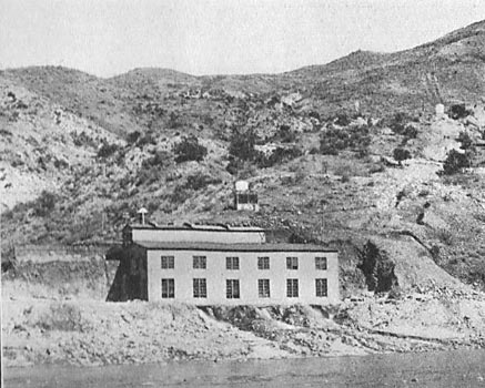
The power house, located on the Verde River, is constructed of rubble concrete. The building is 30 ft. wide, 72 ft. long and 16 ft. high to the crane runway. The transformer house adjoins it and is 16 ft. wide and 60 ft. long.
The entire electrical equipment was supplied by the General Electric Company. Each of the three i800-kw generating units is complete in itself with transformers, measuring instruments, overhanging waterwheel mounted on one end of the two-bearing generator shaft, and an exciter overhanging on the opposite end of the generator shaft.
| |||
| Fig. 1. Interior of Generating Station of Arizona Power Company. |
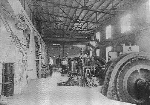
There are no switches in the generator leads; each generator connects directly to its own bank of transformers. No attempt is made to run these machines through any bus system or other parallel connections, excepting to connect the high-tension side of the transformers of each unit to either or both of the transmission lines. The entire arrangement of the station is exactly as though three stations, each with one generating unit, were located at points along the transmission line. This plan is adopted on account of the wonderful success which has always accompanied a single-unit generating station, and, of course, the objection to the single-unit stations is removed by having the other two units close at hand. There is, however, a small set of switches and buses which can take energy from any generator for station use and this bus and these switches are used to hold the generators in synchronism temporarily when starting up, until the main line switches are closed. This avoids the strains incurred in closing high-tension switches with machines slightly out of step, causing surges. There are no exciter buses or switches of any kind in the exciter or field circuits, making the operation as simple as direct-current operation. A special Terrill regulator with three sets of contacts was provided to operate these exciters whenever they are working on the same transmission system; the pilot pressure is taken from the small station bus.
| |||
| Fig. 2. Power House and Penstock Line. |
Each bank of transformers is provided with two 45,000-volt Kelman switches on the high-tension side, one connecting to the north line and one to the south line. Each which is located in a separate room and each bank of transformers is located in a separate room. The transformer and switchrooms are separated from each other and from the generating room by high concrete fire walls, but the roof over these concrete rooms is made of wood and covered with rubberoid roofing. This plan of construction is based on the assumption that if either transformer oil or switch oil has once been raised to a temperature sufficient to ignite it, it is absolutely impossible to extinguish the fire unless air can be excluded or a sufficient amount of water or other cooling medium be placed thereon to lower its temperature. No attempt was made to introduce an air-tight system on account of the extraordinary expense of wall bushings and other devices incident thereto.
 |
| Fig. 3. Map of Transmission System of Arizona Power Co. |
A hydraulic giant, similar to those so familiar in Western hydraulic mining enterprises, is located on the hill above the power house on the side toward which the transformer and switch houses open. When a fire begins in a power house, there are always one or more operators who would be particularly pleased to have an opportunity and a just cause for leaving the scene of activity and those men voluntarily and quickly man the hydraulic giant and turn a stream taken directly from the main pressure pipe on to the roof of the burning switch or transformer room. Drainage is so arranged that this water will not affect the balance of the rooms and in this way a fire which might otherwise be serious is promptly handled and usually without any very bad results, and possibly without shutting down, though this is not likely.
WATER WHEELS.
Each generator is equipped with a 3000-hp waterwheel of the impulse type, made by the Abner Doble Company, of San Francisco. A specially interesting feature of this equipment is the regulation of the speed by needle nozzle throttling of the stream, which is satisfactorily done in spite of the long pipe and high head, by using the Doble needle nozzle form of automatic by-pass relief valves. The by-pass is a needle nozzle similar to the one used on the main wheel and about half the size. Its needle is attached to the governor through the dash-pot and in such a manner as to produce an inverse motion, opening when the main nozzle closes. The dash-pot is similar to the regular arc-lamp dash-pot, allowing easy motion when the governor attempts to close the relief nozzle and acting very -slowly when the governor attempts to open the relief nozzle.
The needle of the relief valve is forced toward the closet position by the action of the water and some heavy springs and it is pulled open by the dash-pot. Two dash-pot needle regulating adjusting valves, one located near the center and the other at the end of the stroke, allow the operator to regulate the speed of closing in two sections. Thus he may allow the relief valve to close quickly during the first half of the stroke and then slowly close the balance of the way.
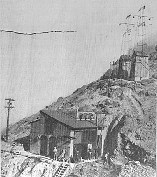
| |||
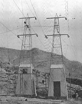
| Fig. 4. Lightning Arrester Houses in Base of Transmission Towers. |
By adjusting these by-pass nozzles to a proper time period the tendency of the governor to fluctuate with the period of pressure fluctuations in the pipe is easily interrupted. The amount of water thus discharged through the by-pass needle is a very minute fraction of the total amount of water used as this opening of the by-pass can be so arranged that it will only occur for considerable movements in the main needle, and need not occur at all on small changes of load, and the water economy is, therefore, not seriously lowered by this device. The usual Lombard oil-filled governors, with a motor-driven pump and an entire equipment of tanks, etc, for each unit, operate these needle valves.
SYSTEM OF ELECTRICAL OPERLTION.
Many years ago the writer was particularly disturbed upon entering a substation of a very large Pacific Coast transmission company by the following notice: "If the power goes off, open all switches and telephone to the chief operator, Mr. ___________ at___________ for orders." Thereupon the writer devised the plan used here and which is now in use on all Huntington systems in southern California, which includes more than 12 power houses and 30 substations in one operating combination, all electrically connected.
| |||
| Fig. 5. Transmission Line Below River. |
This plan again reverts to the wonderful success which accompanied not only single generating stations, but single transmission lines. One of these plants with a single generator and a transmission line, 30 miles in length, with a 15,000-volt transmission, during the years 1897 to 1899, operated for 33 months without an unforseen interruption to the service and the electricity was off the line only four times during that period. The writer's plan, therefore, of operating a transmission system as though there were two separate and distinct transmission lines doing separate and distinct work, grew from this idea. A further consideration which led to this plan was the fact that of all the troubles experienced in the transmission of energy up to that time, 85 per cent of the interruptions which had occurred were due to troubles in switches themselves and not less than two-thirds of these interruptions were due to the accidental or unintended opening of automatic switches and circuit-breakers, due to error and not to any short-circuit or heavy current.
| |||
| Fig. 6. Walker Substation on Prescott Line. |
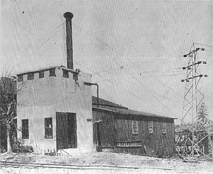
| |||
| Fig. 7. Prescott Substation and Station of Prescott Gas & Electric Company. |
After connecting up several power houses and substations without automatic switches of any kind anywhere on the system (all apparatus, of course, being alternating) the rule posted in the substation differed materially from that quoted above, and was as follows: "Run each of your banks of transformers on one line only, dividing between two lines as near as possible. If the power goes off on one line throw on the other. Quick! Take power from either line as you see fit."
The result is simple; the operator at the power house notes a short-circuited line. His line ammeters indicate that one or the other of the lines is short-circuited. (Only one generating plant in the entire system is allowed to connect the two lines together; all other plants, whether generating stations or substations, operate with each bank of transformers on one line only. The master plant, therefore, controls the situation. All of the generators in that plant are operating on both lines, each generator through its own transformer.) If trouble occurs on one line, the operator opens the transformer switches, disconnecting all of his generating units from the said short-circuited line. This relieves the load on the generators considerably, probably, about half (never all), but immediately the various substation operators; acting without telephone orders, throw in their loads on this generating system and if there are other generating stations, the operator immediately synchronizes the generators which were on the dead line, and throws them onto the live line and thus all substation loads and generators come back at approximately the same time.
In many instances on the Huntington system the entire outfit was transferred from divided lines to one line of the system within two minutes. Substations usually made their change inside half a minute, and frequently in so seconds or less. Thus induction motors are usually supplied with energy before they loose a perceptible amount of their speed. In cases of very long lines, where it is inconvenient to proportion the load evenly between the two lines for maximum economy, a single automatic switch is connected directly between the two lines at some remote point, and as this switch can be adjusted for a maximum current amounting to the difference between loads it opens immediately upon the occurrence of a short-circuit on either line, leaving the system separated as above.
| |||
| Fig. 8. Jerome Substation and Lightning Arrester House. |
Where all loads and generators are thus transferred to the good line the operator of the master power house starts up a spare generator or takes one of the generators from regular service and slowly brings up, the voltage on the line which is in trouble. This avoids all shock and surges on both apparatus and line insulators. If the line shows clear he immediately connects all generators to both lines and the operator at each substation seeing the pilot lamps bright on both lines returns to the original arrangement. After this is all over and the load is again adjusted between the two lines as before, telephoning begins for social purposes as usual, but it is in no wise connected with the operation of the plant except making reports or to arrange with line men for repairs, etc.
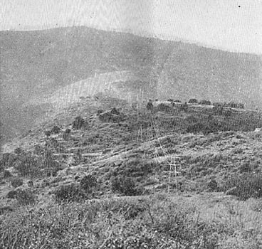
TRANSMISSION LINE.
Two tower bases are enclosed for lightning arrester houses and in them the General Electric electrolytic lightning arresters are located, the horn-gaps being located outside on the usual racks.
The transmission line is composed of steel towers, 45 ft. high with three wires in a vertical plane, on each side of the towers and a steel messenger wire for lightning protection running over the peak. The line wires are 5 ft. apart vertically and so ft. horizontally; the messenger wire being located over the center and 5 ft. above the upper line wires.
Double Thomas 15-in hook and-eye type insulators are used. Thirty-five miles of the line is composed of No. 1 B. & S. seven-strand wire. The two branches 16 and 24 miles respectively from the junction are composed of No. 4 B. & S. three-strand wire running to Prescott and Jerome. Towers were supplied by the United States Wind Engine & Pump Company, Batavia, Ill., and are of the usual rectangular rod and angle-braced windmill type. The wire hardware between insulators and copper is composed of a pair of iron blocks bolted together with four bolts similar to the old bolted come-along which is in turn supported by a link. This clip prevents the slipping of the wire and at the same time is flexible and allows for a change in the position of the insulator without in any way kinking the wire.
| |||
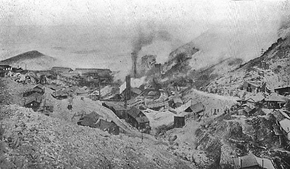
| Fig. 9. United Verde Copper Company's Smelter, and Jerome Substation at Right. |
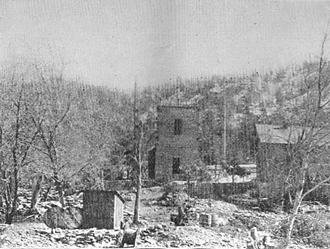
SUBSTATIONS.
Fig. 6 shows a typical substation constructed at Walker, Ariz. These substations have separate switchrooms on the upper floors and transformer rooms below. Each bank of transformers has a high-tension switch connecting to each line. By killing one of the transmission lines from the adjacent substation or the power house, these rooms are rendered entirely safe by opening disconnecting switches underneath the ceiling of the ground floor. The map given in Fig. 3 shows the location of the various substations. For purposes of distribution the line voltage is reduced to 11,000 volts in the substations and delivered to customers at 440 volts, 60 cycles, three-phase.
It is worthy of note that in the entire course of construction there was not a single accident involving serious injury or loss of life. This is remarkable in view of the very large amounts of powder used in blasting. Every pound of material used in the construction was hauled by teams a distance of from 2 to 50 miles; the total amount being 50,000,000 lb.
SERVICE RENDERED.
Two thousand horse-power is now being supplied to the United Verde Copper Company at Jerome, 600 hp of which is transformed into direct current by a General Electric 500-kw rotary converter. Several mines are being supplied with energy and the entire load of the Prescott Electric Company is being carried by the plant. Extensions of distribution lines are being made in many directions from the regular substations located on the transmission lines. The energy is carried at 10,000 volts on three-wire lines erected on wooden poles; this form of construction being adopted in order to facilitate easy moving in the event of changes in the mining location. Steel structures are only used where permanent consumers are located.
The financial interests of the Arizona Power Company have been in the hands of William P. Bonbright & Company, New York. The system was designed and constructed and is now operated by the Electric Operating Construction Company, New York, Messrs. Viele, Blackwell & Buck acting as consulting engineers for the enterprise.
