[Trade Journal]
Publication: Electric Railway Journal
New York, NY, United States
vol. 36, no. 13, p. 465-468, col. 1-2
THE DESIGN AND EFFICIENCY OF HIGH-TENSION INSULATORS
BY A. O. AUSTIN, ELECTRICAL ENGINEER, OHIO INSULATOR CO.
When we consider the importance of the insulator to any transmission system, we are surprised that so little systematic research work has been done. The principal reasons for this are that the manufacturer depends largely on secret processes and that experiments leading to the production of new types must extend over a very long period. In 1904 the Bay Counties and Standard Electric lines of California were being reinsulated, and it was decided to see what improvements could be made. Although the new insulators were the largest then manufactured, it was considered that it was only a matter of time before they would be giving trouble in fog sections.
The early experiments soon made it evident that if improvements could be made in the porcelain body and glaze, the efficiency of the insulator would be increased and its production cost decreased. By 1905 it was found that the high efficiency insulator could be made more cheaply than the regular types. It was during these early tests that there was developed the disk suspension insulator, which has been adopted on practically every transmission line installed in the last two years.
As the current for testing insulators is very small and the potential extremely high, ordinary methods of measurements cannot be used. To analyze the behavior of certain types, it is necessary to try a number of each. The insulator is designed to support the transmission conductors, and is much stronger than the pin or supporting structure, except in extreme cases. Unnecessary mechanical strength in the insulator is to be avoided where it is obtained at the expense of electrical reliability. Although very little has been done along this line, much can be accomplished by making the gripping or cementing surfaces small but of very high efficiency. Electrically, the insulator must prevent serious leakage of current between the conductors or between the conductors and ground, either through the air or over its surface.
While the rating of insulators is usually based on wet or rain tests, much more attention should be given to the dry flashover characteristics. In rating the insulator careful consideration should be given to the effect of locality and the manner of installation. The insulator should be designed not so much for high limits in the laboratory as for working efficiency on the line.
| |||
| Fig. 1 Type A and Type B Four-Shell Insulators |
| |||
| Fig. 2 Type A and Type B Insulators in Multiple |
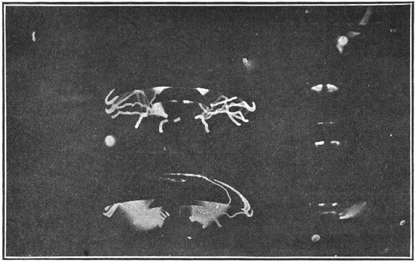
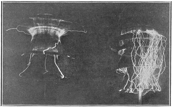
Fig. 1, on page 466, shows two types of insulators, each composed of four shells. These insulators were connected in multiple for the test. In type "A," the low efficiency design, the arc followed a path of 46 in. and built up over the surface, while in type "B," the high efficiency design, the arc built up through the air a distance of 19 1/8 in. The potential necessary to cause this flash-over was 225,000 volts, corresponding to a needle gap of 23 in.
It is well known that a little dirt on a surface will permit flash-overs at a very greatly reduced potential. In analyzing the two styles for dielectric strength, the possibilities of type "B" are very apparent. Type "A" is a four-part insulator with a short inner shell, two large intermediate shells and an 18-in. top. When this insulator is tested under dry conditions, it is found that the small inner shell flashes or spills over at about 200,000 volts depending on the size of the pin and the amount of cement. On an unassembled or part test this inner shell may be tested to flash-over but no higher. It follows that if the same character of flash-over occurs in the assembled insulator, the part receives the same potential, so that assembling gives no gain in the factor of safety against puncture. The same fact holds for the other parts, as the arc is formed over the surface in each case. This reasoning holds no matter what the aggregate of the individual test 'voltages may be. In this particular insulator the sum of the test voltages for the several parts exceeded 270,000 volts, so it might be supposed that some of the parts received a potential at flash-over on the assembled insulator less than on the part test because the assembled insulator flashed over at 225,000 volts. This supposition would be logical if the arc built up over all the shells simultaneously. However, investigation shows that first the small center flashes and then the other shells, one after the other, until the arc extends over the entire insulator. Owing to the large drop in potential over the large shells, the entire series cascades with the spilling of one of them, the complete action taking place during a single alternation. The only intimation of this action is the spilling of the small inner shell, which can be plainly seen since it occurs before the flash-over of the entire insulator. In the assembled insulator when one part is stressed to the flash-over potential before the others, it is said to be overstressed. This overstressing applies to storm conditions as well as to dry flash-overs and it is responsible for the poor showing of a great many insulators.
| |||
| Fig. 3 Overstressed Top Unit of Two Insulators in Series |
| |||
| Fig. 4 Dry Flash-Over Tests on Type B Insulator |
| |||
| Fig. 5 Single Section of Type B Insulator With Tower Eye and Clamp |
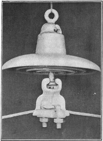
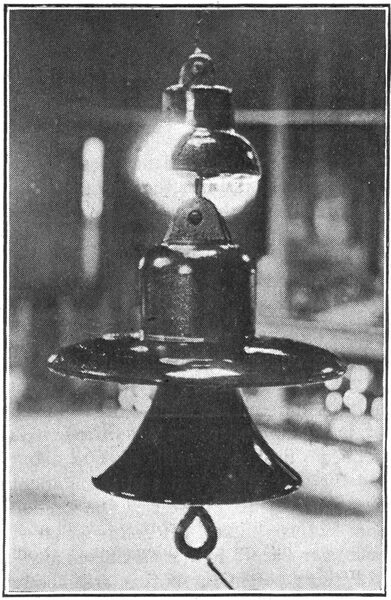
Fig. 3 shows two insulators in series, the top unit of which is overstressed. The charging current for the large unit is seen jumping around the upper unit. The small insulator flashed over when tested alone at 57,000 volts and the larger one at 150,000 volts, while a potential of only 63,000 volts on the series connection was necessary to cause a continuous flash-over of the small unit. On the precipitation test the following results were obtained : Wet flash-over of the small unit, 35,000 volts, of the large unit, 92,000 volts, and of the series connection, 100,000 volts. From this it will be seen that the overstressed member furnished only 8000 volts and was practically worthless when most needed. In addition, the overstressed part was stressed to its arcing potential just before it spilled. This occurred on each alternation and the part was in danger of puncturing.
The two units may be considered as two electrostatic condensers in series, and the drop in potential will be inversely proportional to the respective capacities of the insulators. In the pin type insulator the several parts may be considered a condensers in series, the cement forming the condenser plates and the porcelain forming the dielectric. The electrostatic capacity of the condenser varies directly as the area of the plate and inversely as the thickness of the dielectric. Applying this law to the ordinary pin type insulator, it is seen that the electrostatic capacity of the center shell must be small as compared to the other shells because its cemented area is smaller and the thickness usually greater. Since the electrostatic capacity is least it must carry a greater proportion of the stress on the assembled insulator. This accounts for the frequent puncturing of the center shell on assembled test. The first insulator to be built for an assembly test of 175,000 volts was so designed and the assembled insulator passed the final test without a puncture, the parts first being tested to 60,000 volts each.
If the parts where plain shells are used are too thin, a very high flux density is the result and the parts are flooded with static electricity at comparatively low potentials. This flooding of the surface cuts down the insulation, as the static electricity forms arcs which partially break down the resistance of the air. As the stress in a dielectric varies inversely as the square of the distance from the electrodes, the importance of the distribution of material is apparent.
When the stress is too high the air breaks down and the surface is flooded with charging current or static electricity. The extent of this reduction in insulation is larger than supposed, as was shown by tests on two To-in. disks having the same flash-over distance between the cap and pin. The plain disk flashed over at 65,000 volts and the petticoat disk at 92,000 volts. In each case the shortest distance between the cap and pin was 8 3/8 in. In these designs the addition of i6 per cent in material resulted in an increase of 41 1/2 per cent in the flashover potential. When compared on wet test the increase in the flash-over due to the high efficiency construction was 6o per cent. In addition to standing much higher tests, the high efficiency type did not become flooded with static electricity and also noisy long before the flash-over potential was reached, as was the case with the plain disk. This example alone will show that it is quality of insulation that should be looked for rather than weight.
The following rules apply to any type of insulator and must be adhered to if the corresponding properties are desired:
To obtain a factor of safety against puncture greater than unity in the assembled insulator, the stress on any part must be less than the tested strength of that part.
To obtain maximum flash-over efficiency the equivalent striking distance between the surfaces should be in proportion to the difference in potential between those surfaces.
In addition to the electrostatic electricity, there is a distribution of stress due to surface leakage. The leakage path of a cylindrical rod has for resistance a quantity proportional to the length of the rod and inversely proportional to the circumference of the rod; the resistance of the path per inch length will then be the same at any point. If the diameter of the rod varies, the width of the leakage path varies in proportion to the circumference and the resistance per inch of length at any part will be inversely proportional to the diameter.
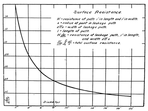 |
| Fig. 6 Relation Between the Diameter and Surface Resistance of Insulators |
The curve, Fig. 6, shows the relation between the diameter and the surface resistance. Where the variables in the leakage path may be expressed in differential form the equation may be integrated to find the resistance for the part. The curve shows that the surface resistance drops off very rapidly with an increase in diameter. The area between two points on the curve represents the resistance between those two points. The total area under the curve is proportional to the resistance of a flat disk. The curve shows that little surface resistance is gained by the use of parts of large diameter and that if the leakage surface is to be effective, it must have length and small diameter.
The vertical petticoat added to a flange furnishes surface resistance of best form, for it has the surface characteristics of the tube, namely, length of path of uniform width. The petticoats on a disk in addition to increasing greatly the surface resistance of the part increase the flash-over potential, thus serving a twofold purpose.
Fig. 2 shows on test two types of suspension insulator in multiple. Type "A" is flashing over while type "B' shows but little static electricity. Type "A" is composed of two 14 1/2-in. sections having a total weight of 45 lb. and a length of 20 1/2 in.; "B" is composed of three 10-in. sections, having a total weight of 24 lb. and a length of 17 1/4 in.
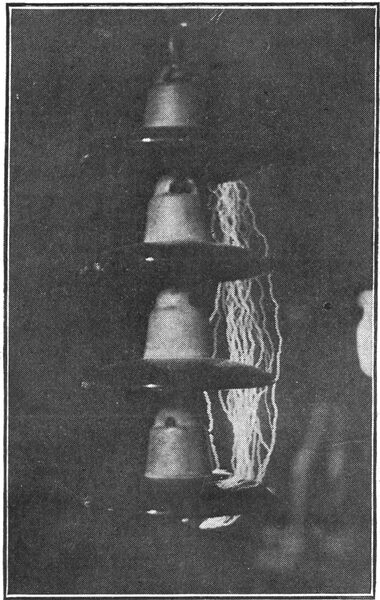
Fig. 4 shows four sections of type "B," on dry flash-over with the arc striking clear of the insulator at 285,000 volts.
The following table shows the properties of a 100,000-volt insulator of each type:
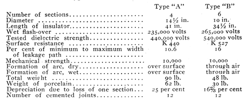 |
The table shows that type "B" is remarkably efficient, accomplishing more than type "A" with approximatelyhalf the material. Fig. 5 shows a single section of the type "B" high efficiency insulator with tower eye and wire clamp. Single sections of this insulator, when provided with an eye pin and cap, are used for guys and to make dead ends on the lower voltage lines found in railway work.
In insulating any line it is well to remember that stress thrown on the insulator, due to lightning, does not depend on the line voltage. For this reason, insulators with a much higher factor of safety should be used on the lower voltages. Types having long narrow shells close to the pin, or having little thickness of material between the pin and the conductor, should never be mounted on a metal pin but on a wooden pin of good length thoroughly impregnated with paraffine or oil. The insulator when mounted in this manner will give good service even when the lightning conditions are severe. In this case the pin must be considered as part of the insulator and the climatic conditions must be such that the pin will not burn. Only moderate sized insulators should be installed in this manner, as the charging current sufficient for the largest types is enough to burn a wooden pin. It is impossible to prevent, breakage on the line, but the insulator should be such that ample insulation remains should one part become broken.
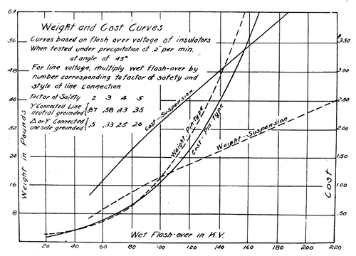 |
| Fig. 7 Weight and Cost Curves of Pin and Suspension Insulators |
Fig. 7 shows some weight and cost curves of pin type and suspension insulators based on the flash-over voltage of insulators when tested under a precipitation of 0.2 in. per minute at an angle of 45 deg.
When lines are equipped with insulators of high efficiency design and great dielectric strength, much of the trouble will be eliminated. Where thin parts are used, a high flux density may be set up in the material and the insulator puncture or shatter like an overcharged Leyden jar. In conclusion it may be said that when the properties which produce reliability in the transmission insulator are fully understood and ample in-sulation is provided, much will have been done to make the transmission line as reliable as possible.
*Abstract of a paper read at the meeting of the Central Electric Railway Association, Indianapolis, Ind., Sept. 22, 1910.
