[Trade Journal]
Publication: Engineering News
New York, NY, United States
vol. 64, no. 17, p. 456-462, col. 1-3
The Track and Line Construction of Electric Railways.
The development of electric interurban railways has reached a point where these lines now form a class by themselves. In view of this fact and of the continuing development of both interurban and intraurban electric railways, we have undertaken an enquiry as to general lines of practice in the track ' construction, pole and line equipment and motor-car equipment of railways of these classes. The results of this enquiry are given herewith in tabular form and are reviewed in the accompanying text. The information given covers 18 interurban railways and 17 street railways in various parts of the country. The former are from 50 miles to 500 miles in length, and aggregate about 3,100 miles of line, with 750 miles of double track. The latter range from 30 to 420 miles, with an aggregate of approximately 2,165 miles. It is to be remembered that there is no hard and fast distinction between street and interurban railway companies. Many street railway companies own interurban lines as extensions, and many interurban companies own street railway lines in towns along their systems.
It is evident that particulars of the track construction and line equipment, etc., of 3,000 miles of interurban railway and 2,000 miles of street railway (about 15 % of the total mileage of such lines) should give some interesting information as to general lines of practice upon railways of this character. This applies especially to interurban lines, all of which have the same general type of track. In regard to street railways, however, only a general idea can be given as to track practice (and mainly as to the materials used), since there is no general type of construction. This feature of street railway tracks was discussed editorially in our issue of Aug. 4. With this statement in regard to the general purpose of our enquiry, we turn to the review of the information presented in the accompanying tables.
Roadbed and Ballast.
The width of roadbed is very much the same as in steam railway practice. For single track it ranges from 14 to 16 ft. on banks and 20 to 24 ft. (over ditches) in cuts. For double track it ranges from 24 to 32 ft. on banks and 34 to 41 ft. in cuts. It may be noted that the American Railway Engineering Association has recommended (for steam railways) a uniform roadbed width for banks and cuts, the width to be 20 ft. for lines of heavy traffic and high speed, 16 ft. for medium traffic and speed and 14 ft. for lines of light traffic and low speed. The general opinion, however, is that 16 ft. should be the minimum (especially in cuts), whether for steam or electric railways.
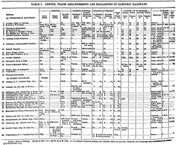 |
Ballast is mainly of gravel, but stone also is largely used; slag and cinders are used to a limited extent. For stone ballast, the requirements as to size vary considerably. Some roads specify but one size, while others specify a range of sizes. The graded sizes, of course, give a greater density. There is a somewhat general use of a minimum amount of ballast, a depth of 6 ins. under the ties being used in several cases. This is due partly to reasons of economy, but probably it is due more largely to the fact that a traffic of electric cars (or trains) does not require so heavy a bed of ballast as a traffic of steam locomotives and trains, with the heavier concentrated loads and the heavy pounding incident to these locomotives. However, on some lines the depth is from 8 to 12 ins. On street railways the ballast is laid in a trench and protected by the pavement, while it is frequently rolled with steam rollers in order to avoid future settlement under traffic. A depth of 6 ins. is general (less in some cases); the maximum given is 15 ins., but this probably is the total depth including the tie, or, say, 9 ins. under the tie.
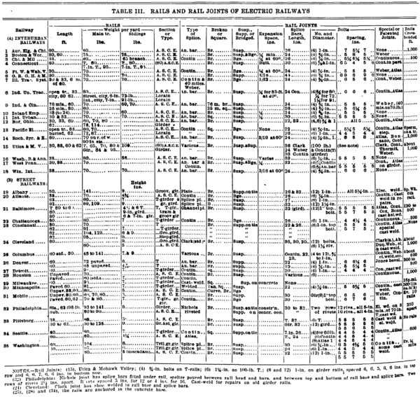
Rails and Rail Joints.
The rails on the open track portions of interurban railways are almost invariably of the Am. Soc. C. E. sections, averaging 70 to 80 lbs. per yd. in weight, and being generally 30 or 33 ft. long. While 60- ft. rails are used by several lines, they are found difficult to keep in line and surface. The rails are laid usually with broken and suspended joints, although there is extensive use of various patented joints which give a base or bridge support between the joint ties. Short splice bars with four bolts are used in the great majority of cases, 24-in. bars being most common. The lengths range as high as 30 and 36 ins., with 1 ins. as an exceptional case; six bolts are commonly used for these longer bars, and one road uses six bolts in 26- in. splice bars. For the joint bolts, a spacing of 4 ins. and 5 ins. is general, with a maximum of 9 ins. in a 44-in. splice. Square nuts are used almost universally, and nutlocks are used in a majority of cases.
All joints are, of course, bonded electrically for the return current, and the wider bolt spacing (7 to 9 ins.) is sometimes adopted to give sufficient room for the attachment of the bonds. The activities of copper thieves make it desirable to have the bonds as inaccessible as possible, and this has led to the adoption of various concealed or protected bonds.
The rails of the track are connected by cross bonds at intervals of 500 to 1,000 ft., and on double track the tracks are cross bonded. In many cases, however, these bonds gradually disappear (by theft) and are not re placed. The rails and joints of street railway track present a much greater variety, as noted above. In the first place, there are at least four types of rail sections: T-rail , T-girder, step head and grooved head. In the second place, each of these types is represented by innumerable sections differing in dimensions and in details of form. Rails 60 and 62 ft. long are used extensively, and while there is little trouble in maintaining the surface, there is trouble in holding long and high rails in line. For this reason, among others, tie bars between the rails or brace plates to support them from the outside are used in a number of cases.
 |
High girder rails require high splice bars, and as a rule two rows of bolts are used, usually six in each row. In addition to various patented types of splice joints affording a base support, extensive use is made of welded joints; these are of two types ( 1 ) cast weld or thermit weld, in which the rails themselves are welded together; (2) electric weld, in which splice bars are welded to the rails (Eng. News, Sept. 1) . At Cleveland and Philadelphia, riveted splices are used (with welded reinforcement in the former case). The rail joints are fitted with copper bonds (except in the case of welded joints), and the rails are cross bonded at intervals. At Cincinnati, however, no electrical bonding is required, since the double- trolley system is used, and the second wire (instead of the track rails) forms the return circuit. The same applies to the conduit lines at Washington, both positive and negative (or return conductors being laid in the conduit.
Rail Fastenings.
The rail fastenings used on interurban rail ways are almost exclusively common drive spikes; they are of the large size used by steam railways, 9/16- in, square and 542 ins. long. Very little has been done towards introducing any better form of fastening. On curves, rail braces are used to support the rails against lateral pressure. On sharp curves, also, guard rails are frequently used, in order to relieve the outer rail from excessive pressure. Their use is probably more general than on steam railways (comparatively speaking), owing to the use of curves of much shorter radius than those on the main tracks of steam railways. For street railways , common spikes are used with wooden ties, although screw spikes are being introduced to a limited extent. With steel ties, the fastenings are either bolts or keys. Where the ties are widely spaced and the rails rest upon the concrete base, the rails are sometimes attached to bolts, chairs or anchors embedded in the concrete as an additional means of fastening, the widely-spaced spike fastenings being insufficient. With high rails, tie bars are commonly used. There are flat bars (set on edge) and having the ends turned and threaded to pass through the rail web and be secured by nuts. Some roads, however, prefer a combination tie - plate and rail-brace to the tie-bar, as interfering less with the paving. The tie - bars and brace- plates are used on tangents as well as curves. In some designs of track, the rails are held both vertically and laterally by embedding the base in concrete, but this presents difficulties and objections for rail renewals.
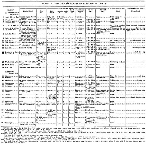
Ties and Tie Plates.
Wooden ties are used almost exclusively. Oak, cedar and chestnut seem to be most generally employed. The prices quoted have a wide range, as might be expected, due to variations in the quality required and in the distance from source of supply. White oak has a range of $0.10 to $0.90; cedar, $0.55 to $0.63; chestnut, $0.10 to $0.53, and pine, $0.25 to $0.75. The experience or estimates as to life have an equally wide range, varying with the quality of the wood, the local climatic and soil conditions, and the character of the track and traffic. Oak shows a range of from 8 to 20 years; cedar, 12 to 15 years; chestnut, 7 to 12 years, and pine, 7 to 20 years.
The renewals are made mainly on account of decay rather than of mechanical wear or disintegration. The reliability of the statements as to the life is very doubtful, as few railways of this class keep systematic records and comparatively few have been in operation long enough to have any extended or definite information on this point. It may be noted that one high-speed line with exceptionally heavy traffic, which has been in operation for ten years, finds that most of its original cedar ties are still in good condition while a number of the original oak ties are being removed on account of decay.
 |
As to the sizes of ties, for both interurban and street railways a length of 8 ft. and a section 8 ins. wide and 6 ins. thick are the usual dimensions. On third-rail lines, occasional ties of extra length support the conductor rail. A few street lines use 642 to 7 ft., and one interurban line uses 7 ft. A few street lines also specify widths of 9 or 10 ins., and a few interurban lines specify a thickness of 7 ins. These dimensions, of course, represent only general averages.
The number of ties per rail length of 30 or 33 ft. is from 14 to 18, with 26 to 32 ties for 60 - ft. rails. A spacing of 24 ins. is very common, with 18 to 24 - in. spacing at the joints. This applies to both street and interurban lines; but in the former case, especially with girder rails, a tie spacing of 5 to 12 ft. is used sometimes, the concrete base being relied upon to support the rails,
Treated ties are used to a surprisingly small extent either in the open track of interurban railways or the buried track of street railways, as far as the tables show, and we believe the returns of these 35 lines are fairly indicative of electric railways in general. This may be due to the use of ties of lower cost than those used by steam railways, and to the comparatively long life of such ties under the conditions of traffic construction on electric railways. The preservative medium is principally creosote, and this is applied usually by the pressure process; zinc chloride is used also, and some lines have used ties treated with carbolineum by the open- tank process.
Steel tie-plates appear to be used very much less than on steam railways. This may be accounted for in part by the absence of the enormous concentrated loads upon locomotive driving wheels, and in part by a policy of introducing these tie - plates only when the ties begin to show signs of wear, thus economizing in first cost of track construction.
Steel ties are mentioned by only three inter urban lines. One of these uses them on a viaduct and it appears likely that the others use them at points, where the tracks are laid in paved streets. Several street railways use steel ties to some extent. Concrete ties are mentioned by three street railways; their use is experimental and in one case they have proved unsatisfactory.
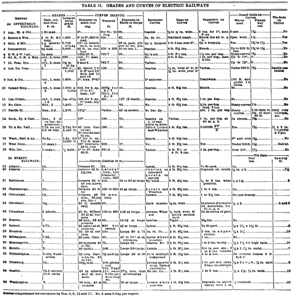
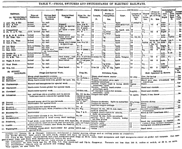
Switches and Frogs.
In switch and frog construction, electric inter urban railway practice differs but little from that of steam railways. Spring-rail frogs are commonly used in turnouts for main track, and bolted frogs are used more than any other type, while the use of hard-steel wearing parts for frogs is general. Turnout frogs are usually No. 7 to No. 10; anything above No. 10 is exceptional, while on steam railway lines frogs of Nos. 10 to 12 are usual (with higher numbers where speeds are high) . A 15-ft. guard rail at frogs is general. The flangeway width at frogs and guard rails ranges from 1-1/4 ins. to 1-7/8 ins., or even 2 ins.
The split switch is used universally, and the length of switch rail is usually 15 ft., but the throw of the switch point varies from 3 to 5 ins. The automatic switchstand (allowing cars to trail through a closed switch) is used more extensively on electric than on steam railways. Of 18 interurban railways: 10 use automatic switchstands, four use rigid switchstands, and four use both types.
Distant signals at turnouts are used only occasionally, and the use of block signals has not made much progress on interurban railways, even where the trains are fast and frequent.
 |
With street railway track there is a special type of switch and frog construction, to meet the conditions imposed by the paving. Each switch has usually a pivoted tongue or switch rail on one side, and a fixed point or "mate" on the opposite side. A deep opening cannot be permitted and the tongue is a shallow bar, from 5 to 12 ft. in length, pivoted at the heel and sliding in a trough or grooved rail. At junctions and intersections much special work is required. Frogs, switches and special work are built frequently of hard-steel throughout or with hard steel inserts (renewable or otherwise) for the parts taking the greatest wear. The switch tongue is operated usually by hand, either by the motorman or switchman. In a number of cases, however, facing switches are operated electrically.
Signal systems are used by a number of street railways to govern the movements of cars at junctions and intersections, and also at passing sidings to provide a block system on single track. This last consists usually of lamps (with a disk as auxiliary), operated either by a lever within reach of the motorman or automatically by a de vice on the trolley wire. In most cases a number of following cars can pass in one direction, the signal at the entrance of the block indicating that a car is already in the block but proceeding in the same direction. As long as the "clear" or " caution " signal is displayed at one end of the block, a "stop" signal is displayed against op posing cars at the other end of the block.
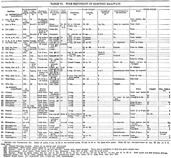
Pole Line and Overhead Equipment.
The poles supporting the overhead work are usually spaced about 100 ft. apart, but the spacing varies from a minimum of 80 or 90 ft. to a maximum of 150 ft. The space is reduced usually on sharp curves. On open lines, the distance of the pole from the center of track is from 7 ft. to 8 ft., and a minimum clearance of 5 ft. from the nearest rail is desirable. Side poles have a slope or rake of 1 in 24 to 1 in . 30. On streets the poles are usually set at the curb line (or just inside the curb so as not to obstruct the gutter) , but where the streets are very wide the poles are set sometimes in the middle. The poles range from 30 ft. to 65 ft. in length, the longer poles being used at crossings and where transmission lines are carried. Lengths of 30 and 35 ft. are the most general, and the pole is set usually about 6 ft. deep.
 |
Wooden poles are usually of cedar, with chestnut and pine coming next, and creosoted pine is used in some cases. The cost ranges from $5 to $10 for cedar and $3 to $8 for chestnut, depending, of course, upon the size and quality. Statistics as to life are very limited, and estimates range from 8 to 20 years for cedar (with 15 years as a general average), and an average of 10 years for chestnut. Treated poles are used only to a limited extent, and these are usually treated either with creosote or carbolineum. There is a somewhat more general use, however, of poles whose butts are treated by being dipped in or painted with some preservative.
Steel poles are generally used by street railways, and also by interurban lines where these tracks run through streets. Tube poles 30 ft. long, in three sections, with a 5-in. diameter for the top section, are common; although some roads use an 8-in. top section either for line poles or for curves. The cost varies from $20 to $40, according to the style of the pole and the condition of the metal market. Lattice and other special forms of steel poles are used to some extent, especially where high poles for transmission lines are required. The life of steel poles is given as 20 years, but may be prolonged indefinitely if the poles are given proper care against rusting and electrolytic corrosion. Concrete poles are used but little, and only in an experimental way.
The overhead trolley - wire system for the distribution of current is used in the great majority of cases, only a few interurban lines having adopted the third- rail system. There are two principal methods of supporting the trolley wire: ( 1 ) by transverse span wires attached to poles on both sides of the track; (2) by bracket arms on poles at one side of the track. Interurban lines use both systems almost equally, but with a preponderance in favor of the bracket arm system, and where a road reports both systems in use it is probable that the span wire system is adopted mainly where the line passes through streets. In exceptional cases, the wires are carried by steel bridges spanning the tracks; this is generally in connection with long spans of catenary wire supports. On street railways, the span-wire system is used in a great majority of cases. In very wide streets, however, a single line of poles (with double bracket arms) is sometimes placed in the middle of the street and between the tracks. Where side poles are used, the second trolley wire at passing sidings may be attached to span wires, to long bracket arms, or to brackets on a second line of posts outside of the siding. The trolley wire is usually 18 to 20 ft. above the track, or 21 to 22 1/2 ft. over railway crossings. The minimum height, as in passing under bridges or track elevation work, is about 12 1/2 ft.
As to the electrical distribution, the direct current system with 550 to 600 volts is used by a majority of the lines shown in the tables, and by a majority of all street and interurban lines now in operation. Single-phase and three- phase lines are exceptional, but the table includes three interurban lines using alternating current of 3,300 and 6,600 volts.
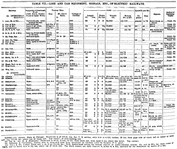
Car Equipment.
Interurban railways use double-truck cars almost exclusively; these are from 45 to 60 ft. in length and weigh from 23 to 50 tons. As a rule each car is equipped with four motors of 56 to 125 HP. The schedule speeds are from 25 to 40 m. p. h. , with maximum running speeds of 40 to 73 m. p. h. The cars of street railway lines are from 28 to 50 ft. in length, and in large towns the double-truck type of car is commonly used. The weight and motor equipment vary considerably. The speeds in the streets are from 8 to 12 m. p. h. , varying according to ordinance requirements and to the traffic conditions; on suburban lines the speeds run up to 15 or 20 m. p. h.
Census Report on Electric Railways.
The special report on street and electric rail ways in 1907, published recently by the Bureau of the Census (U. S. Department of Commerce and Labor) covers 945 railways in operation during 1907. The use of electricity by line transmission was reported by 902 companies having an aggregate of 34,034 miles of track and about 25,000 miles of line. At that time, electricity had almost superseded all other kinds of motive power, the miles of track operated by cable, steam, gasoline and animal power aggregating only about 344 miles of track, out of a total of 34,404 miles (or only 1% of the total) . As to the system of operation, it appears that 895 electric companies (32,502 miles of track) used the overhead trolley system, 23 companies (1,210 miles) used the third-rail system and 10 companies (323 miles) used the underground conduit system. One line of 22-1/2 miles used gas-electric motors, and one of three miles used storage batteries.
Of the 34,404 miles of track of electric rail ways in 1907, the surface tracks represented 98.7%; elevated lines, 1%, and subway and tunnel lines only 0.3%. Again, 60.6% of the surface trackage was on private right-of-way and 39.4% on public thoroughfares.
 |
Some of the track statistics with regard to track construction may be reviewed with interest, bearing in mind that they relate to conditions now nearly four years past. Of 914 companies, 90 used rails of 100 lbs . per yd. and over, 277 used rails of 80 to 95 lbs. , and 281 used rails of 70 and 75 lbs. Furthermore, 900 companies used T-rails, 387 used girder rails and 128 used grooved rails. Just what is meant by girder rails does not appear, as many grooved rails are girder rails. As to the ties, oaks (of all kinds) represented nearly 40 %, and chestnut 23 %. The average cost per tie was $0.56; or $0.59 for oak ties, 0.50 for chestnut , $0.47 for cedar. and $0.60 for southern pine. Of 23,060 miles of over head trolley line, 56.2% was supported by span wires, 40.6 % by side bracket poles, and 3.2% by center poles. Steel and concrete poles were used on 15% of the mileage, but the latter are still in the experimental stage and used only to a very limited extent. The cost of wooden poles averaged $5.77 for cedar, $4 for chestnut and cypress, $6.33 for pine and $3 for oak.
In regard to the catenary system of supporting the trolley wire, it is stated that this is used on both direct- current and alternating-current systems, but no figures are given as to its mileage:
Catenary construction was adopted in this country primarily for use on single- phase alternating current lines, but it a numerous mechanical advantages have led to its adoption by a number of roads using direct current. These advantages consist in a wider pole spacing and flatter (more nearly horizontal-Ed.) trolley wire, flexibility of suspension, minimizing the effect of the blows of current collecting devices at the suspension points, and finally a reduction in the breakage of trolley wire under the strain of supporting the weight of its entire span between poles. For high tension a. c. and d. c. trolley work, the insulation possible with the ordinary form of construction is insufficient. With catenary construction the messenger or supporting cable can be insulated for the highest voltage yet proposed for any trolley line.
Of 6,279 grade crossings of steam railways by electric lines, 3,690 were " protected," but this protection includes everything from separated grades (not a grade crossing) to a mere alarm bell or flagman. There were 14,546 miles of telephone line used exclusively for the operation of electric railways.
 |
The total number of passengers on electric railways in 1907 was 9,533,080,766, and 1% of these were free. The total car mileage was 1,617,731,300, of which only 2% was represented by freight, mail and work cars and electric locomotives. The car-hours aggregated 151,338,944. The total number of cars was 83,641, of which 70,016 were passenger cars and 68,874 were fitted was with motors. Of the motor cars, about 72% had two motors and 27% had four motors. The fare passengers averaged 216,522 per mile of track, 4.70 per car-mile and 43.06 per car - hour.
BLOCK SIGNALS AND TRAIN DISPATCHING.-- One other point upon which we may touch is the system of handling traffic. No statistics are given, but it is stated that with few exceptions the interurban lines use the telephone train dispatching system. Train- order signals, operated automatically from the dispatcher's office, have been installed in large numbers as valuable adjuncts to the ordinary dispatching system." This system, with the train-order automatic signals sometimes used in connection with it, was described in our issue of Sept. 29. The statement in the census report as to the use of block signals is as follows (slightly condensed), and this matter of the use of the block system on electric railways was discussed editorially in our issue of Sept. 29:
A great deal of interurban mileage is single track, and automatic block signals have not yet been adopted to any great extent for long stretches, although they have proved valuable at points of congestion or special danger. A few of the later double - track roads, which approximate closely in methods to the steam railways, operate automatic block signals, using track circuits. But the cost up to the present time has been so great, it is said, as hardly to warrant the investment.
