[Trade Journal]
Publication: Electrical World
New York, NY, United States
vol. 54, no. 19, p. 1127-1128, col. 1-2
ELECTROSTATIC LIMITS IN HIGH-TENSION
TRANSMISSION-LINE INSULATORS.
With the extension of the long-distance transmission industry there has been a continual crowding upward of the line voltage. For several years the transformers and other high-tension apparatus could be had for voltages much in excess of the highest practicable transmission voltage, which voltage was limited by the line insulators. Line insulators, at first designed almost wholly to fulfil mechanical requirements, increased in size and complication until their cost and weight became prohibitive and constituted a limitation of transmission voltage.
The economics of transmission called so, insistently for higher voltage that transmission engineers were tempted time after time to lay out systems for voltages above standard and take it upon themselves to design insulators to fill the requirements. These attempts were seldom attended with success, and the cost was always excessive. The designs may be roughly divided into two classes—standard and freaks. The standard designs were usually successful, but their extreme weight and cost quickly became intolerable as the voltage went up. The freaks were usually based on guesswork, made in the blind hope of improving the standard type, and were unsatisfactory. Most of the freaks were impossible from the porcelain manufacturers' standpoint, and thus after being redesigned were built and installed on the line only to be scrapped or continued in operation at reduced voltage.
 |
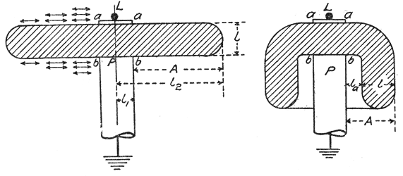
| Figs. 1 and 2—Elementary Types of Insulators. |
The invention of the suspension type insulator cleared the whole subject and set things going along the proper lines. With this type of insulator the voltage limitation of transmission lines has been transferred to the line itself, and at present it is determined by the critical voltage at which the energy loss to the atmosphere becomes excessive.
The extreme importance of the subject has caused it to be deeply studied both here and abroad, and, although most of the progress has been the result of experimental work, the radical and rational improvements have been due to proper consideration of the theory. Quantitative theoretical investigation of insulator design is not yet possible, except to those who have proper equipment for experimental determination of the factors involved. On the other hand, a qualitative analysis is easily made and serves well the purpose of indicating the effect of the different factors which enter the design.
Electrically considered, the insulator is a more or less complicated condenser, and evidently it should be so proportioned as to give a favorable distribution of dielectric flux. Large capacity means a correspondingly large charging current, and this current spreads itself over the surface of the insulator, ionizes the air and reduces its dielectric strength, thus preparing the way for the formation of corona, streamers and flashovers in succession. The effect of rain is to increase the capacity of an insulator and thus greatly to aggravate the tendency to flash over.
 |
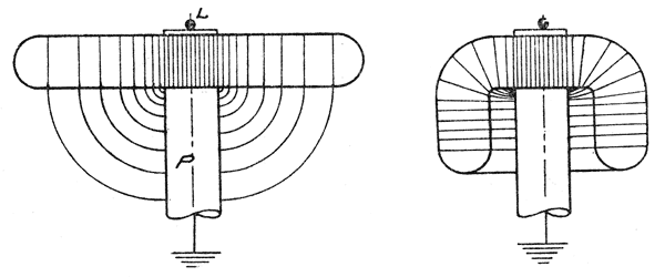
| Figs. 3 and 4—Elementary Types of Insulators. |
In order to determine the effect of shape and relative proportions of the parts upon the effectiveness of an insulator it is convenient to consider two elementary types, as shown in Figs. 1 and 2. Fig. 1 shows a flat circular porcelain disk; L represents the line conductor and P the insulator pin. In Fig. 2 is shown the same insulator bent into the form of a cylindrical cup. The current taken by the insulator may be resolved into two components—the charging current in leading time-quadrature with the e.m.f. and the leakage current in time-phase with the e.m.f.
The leakage current has two paths—one directly through the mass of the insulator and the other over the surface. Experiments by Mr. C. E. Skinner (1) failed to indicate any perceptible current through porcelain, and, therefore, it is safe to, assume that the conductance of an insulator is that of an infinitely thin surface film, all top surfaces of which may be wet. Referring to Fig. 1, and assuming the top to be wet and of negligible resistance, the conductance is
 |
where k is a factor depending upon the character and condition of the surface. This equation indicates that increasing l2 and decreasing l1, decreases the conductance almost in direct proportion to the ratio. Bending the disk into the form of a cup, as shown in Fig. 2, decreases the cross-sectional area of the leakage path and therefore decreases the conductance. It is equivalent to cutting a sector from the flat disk; however, this decrease in leakage conductance is offset to a certain extent by reason of the redistribution of the dielectric flux, as will be shown later.
The charging current spreads itself radially from the conducting portions L and P over the surface of the disk, as photographs published by Mr. Karl Kuhlmann in the Elek. Zeit., Jan. 20, 1910, have shown plainly. In Fig. I the arrows represent the direction and amount of the current.
The general formula for capacity is
 |
wherein k is the dielectric flux constant, A the cross-sectional area of the dielectric circuit and 1 the length of the dielectric circuit. The dielectric flux constant is a property of the material and is a measure of the dielectric flux which will be established by unit potential gradient. When two dielectrics are connected in series and traversed by a flux of uniform density they divide the voltage in inverse proportion to their dielectric flux constants.
 |
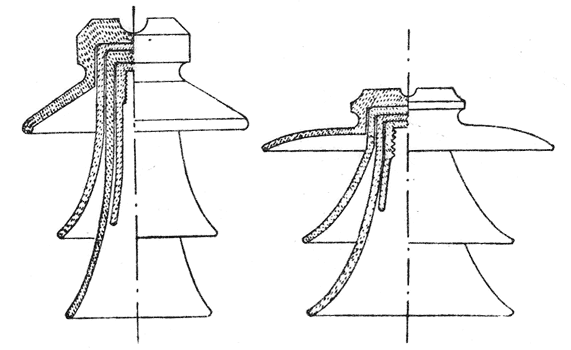
| Figs. 5 and 6—Practical Types of Pin Insulators. |
Considering the disk, Fig. 1, the dielectric flux between L and P will be almost entirely through the porcelain disk due to the large dielectric flux constant of porcelain and the shortness of the path. Assuming rain conditions—that is, the upper portion of the surface as a conductor—the distribution of dielectric flux is about as shown in Fig. 3; the flux which goes out into space is neglected. A casual examination shows that a very pronounced maximum strain exists at the center, where the proper value of dielectric strength can easily be obtained. Next taking up the cup-shaped insulator under rain conditions and comparing it with Fig. 2, the approximate dielectric flux distribution is shown in Fig. 4. At a glance it is seen that the total flux and, therefore, the charging current are greater, the zone of maximum flux is much less pronounced, and the worst effect of all is the enormous increase in the strain produced in the air inside the cup. The dielectric flux constant of porcelain is about five times that of air. Therefore, assuming the porcelain to be of the same thickness as the air space, the relative dielectric conductances are as 5 is to 1; that is, if 60,000 volts are impressed across the two there will be 10,000 volts across the porcelain and 50,000 volts across the air. Not only is this great stress liable to break down the air-gap, but it renders the surface film more conducting and. therefore, also increases the leakage.
This theory of the insulator, which demonstrates the futility of petticoat insulators that cling about the pin, is well borne out in practice. In an article by Mr. A. S. Watts in the Electrical World, May 19, 1910, in which was discussed in detail the development of the present types of insulators, the two types shown in Figs. 5 and 6 were described. These insulators are shown to the same scale and appear to weigh about the same. The elongated type worked well at 45,000 volts, but for higher voltages it was impracticable to design one that would not break down under storm conditions. The expanded type, on the other hand, was successfully used at 75,000 volts. This is a striking illustration of the effect of storm conditions on the distribution of stress in an insulator.
The suspension insulator may be classed with the disk type, Fig. 1. Not only is the insulator itself a marked improvement over the pin type, but the method of installation introduces important improvements in the reliability of operation. Being beneath the metal cross-arms it is practically immune from lightning troubles, and judged from the mechanical standpoint the flexible suspension relieves the cross-arm from torsional stresses and reduces the stresses due to wind and to accidental breakage of a conductor. From the operating standpoint the suspension insulator leaves= little to be desired. However, owing to difficulties encountered in the erection of lines using this type of insulator it is not practicable to use it in all cases. There is a certain voltage above which the extra cost of installation of the suspension insulator is justified by the saving in cost over the pin type. It is used in many lines of over 60,000 volts and is considered standard for e.m.fs. above 80,000 volts.
(1) Trans. A. I. E. E., Vol. XXVII, p. 928
