[Trade Journal]
Publication: General Electric Review
Schenectady, NY, United States
vol. 13, no. 1, p. 24-29, col. 1-2
TRANSMISSION SYSTEM OF THE SOUTHERN POWER COMPANY
BY JOHN LISTON
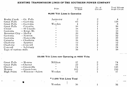
The cotton mills of the Piedmont district take about 80 per cent. of the entire output of the Southern Power Company's generating stations, the balance being utilized in various other industries and for lighting. The scattered location of the numerous mills in North and South Carolina rendered the problem of economical transmission unusually complicated, and it was necessary to provide several main transmission lines with a number of branch circuits and taps to the mills; so that the present transmission system, as indicated in Fig. 1, involves a network of 11,000 volt, 44,000 volt and 100,000 volt, three-phase, 60 cycle circuits, which have an aggregate pole and tower length of 639 miles, with a single circuit total of 98.3 miles.
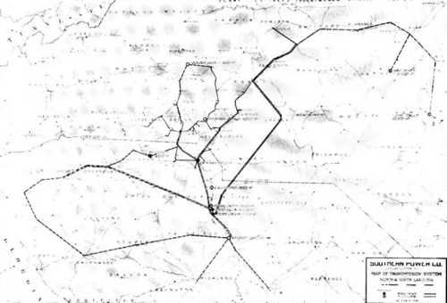 |
| Fig. 1. Map of Transmission System Showing Existing and Projected Lines |
The present lines extend north from the Rocky Creek power station for a distance of more than 100 miles, while their range east and west is approximately 165 miles. When the new power stations and the projected lines are completed the total mileage of the transmission system will be more than double that of the existing lines.
The main generating stations at present constructed are arranged for parallel operation and are tied together by means of a trunk line with three circuits, two circuits on twin towers and one on poles running from the Great Falls and Rocky Creek stations to Catawba. The general transmission system is not, however, operated as a trunk line, but the various sections are interconnected through four main switching stations, and 57 local transformer sub-stations. These insure uninterrupted service in case a genera-ting station is either overloaded or shut down. If trouble occurs on any one of the lines, the particular section affected can be readily cut out and the balance of the line fed through the switching stations at either end. The entire system is patrolled each week, fourteen men being employed in this work. They keep the right of way clear and do all ordinary repair work; under normal conditions each man patrols a limited territory, but in case of serious trouble an effective communication system enables them to be readily assembled within a short time after the discovery of the trouble.
At present the total transformer capacity of the local sub-stations on the 11,000 volt lines is 7000 kw., and on the 44,000 volt lines 55,350 kw. In the 17 stations on the 11,000 volt lines the secondaries of the transformers are arranged for 550 volts. On the 44,000 volt lines there are 22 stations having transformers with 2300 volt secondaries, and 8 stations having transformers with 550 volt secondaries. Nine stations are already provided for the 100,000 volt lines, and these all have transformers with 2300 volt secondaries. In addition to these, two stations on the 100.000 volt line will have transformers for stepping down to 44,000 volts, for tying in with the 44,000 volt system in case of breakdown.
At present a total of 130,000 kw. in 100,000 volt transformers has been installed. In all sub-stations on the 100,000 volt lines three single-phase transformers will be used, and in no station will the capacity of the transformers he less than 1000 kw.
The main switching stations referred to above have operators. but most of the local transformer sub-stations do not require the services of special attendants.
At present the transformer connections throughout the system are delta-delta, from generating station through sub-stations to the mills. When the 100,000 volt system is put in operation, the transformer connections at the generating station will be changed to delta-Y, and those at the junctions with the 44,000 volt line to Y-delta.
A reference to Fig. 1 and the following tabulation will give an idea of the extent of territory covered by the existing lines, and will indicate the problems which confronted the engineers of the Company when planning the routes to be followed, so as to obtain economical current distribution and, at the same time, secure immunity from serious interruption of the service; this latter feature being further complicated by the frequent local lightning storms which are characteristic of the region served.
| |||
| Fig. 2. Single and Twin Circuit Poles |
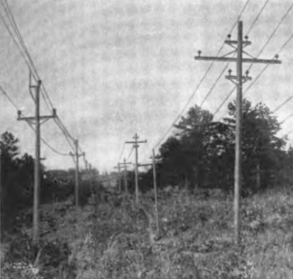
For the various transmission lines five distinct types of poles and towers have been used. The two forms of wooden poles shown in Fig. 2 were used for the original Catawba transmission linethey are either cypress. juniper or chestnut (chestnut being finally selected as the most suitable available wood), and the cross arms are all of hard pine creosoted. The twin circuit pole shown on the right hand of Fig. 2 is used for 11.000 volt circuits, while the single circuit poles at the left now carry 44.000 volt conductors, and will also be used for a short 100.000 volt line.
| |||
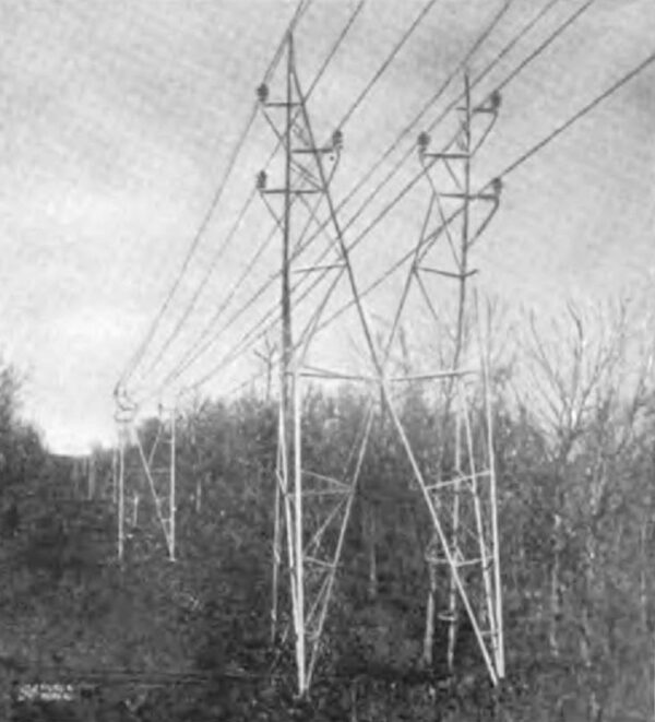
| Fig. 3. Twin Circuit \"Aeromotor\" Towers Carrying 44,000 Volt Conductors |
| |||
| Fig. 4. 100,000 Volt \"Milliken\" Towers With One Circuit Strung |
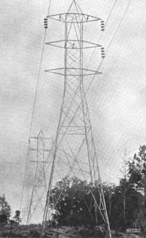
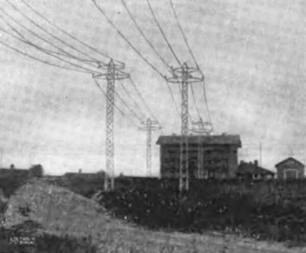
The bulk of the 44,000 volt lines are now carried on twin circuit structural steel "Aermotor" towers similar to that shown in Fig. 3, while for the intended 100.000 volt lines a 3-arm steel twin circuit "Milliken" tower (see Fig. 4) has been provided. These towers are practically duplicates of those used in the Schaghticoke-Schenectady line of the Schenectady Power Company. which were fully described in the May. 1909 REVIEW.
| |||
| Fig. 5. 44,000 Volt Lines Entering the Gastonia Substation |
For running tap lines to mills and carrying the conductors across railroad tracks and through cities, a type of pole similar to that used for the Chicago Drainage Power Transmission system (see Fig. 5) has been adopted. These are twin circuit 2-arm poles built of structural steel, and are used intermittently in the different transmission lines, their height varying from 45 to SO feet, the 80 foot poles weighing 9,000 pounds each. These poles, as well as all the "Aermotor" type, have their bases weighted with concrete.
The "Milliken" towers are mounted on metal stubs sunk 6 feet in the ground. Where the angle of the line is over 15 degrees, however, these stubs are weighted with rock and concrete, and where an angle of over 30 degrees occurs, two and sometimes three towers are used for making the turn. The weight of the standard "Milliken" tower is 3089 pounds, and its height from ground line to peak 51 feet. The towers are spaced to average 8 to a mile and a strain tower weighing 4230 pounds is used every mile. For particularly long spans a special heavy tower weighing 6000 pounds is used. The circuits are transposed every 30 miles. The magnitude of the operations carried on by the Southern Power Company will be indicated by the fact that there are 2157 of these "Milliken" towers already erected, having a total weight of almost 3700 tons.
 |
The "Aermotor" towers vary in height from 35 to 50 feet, and the circuits are transposed every 10 miles. All steel towers were assembled on the ground and erected by means of gin poles.
Both copper and aluminum conductors have been used in the construction of the line. On the 44,000 volt, 2-circuit trunk lines, from Great Falls to Catawba, a No. 000 6-wire stranded copper cable weighing 8 tons per mile of two circuits and provided with a hemp core, has been used. On the 18 mile line between Catawba and Charlotte the two single circuit 44,000 volt wooden pole lines carry an aluminum cable weighing 1029 pounds per mile. This cable is 6-strand with a cross section of 208,000 cir. mils.
For the 140 miles of 100,000 volt line from Great Falls to Greensboro a No. 00 7-strand copper cable weighing 2144 pounds per 2-circuit mile has been used.
All conductors except those on the 100,000 volt lines are carried on triple petticoated pin insulators. The center stud provided with these insulators is of special design, and is the invention of Mr. W. S. Lee, Vice President and General Manager of the Company; it permits the rapid replacement of insulators in case of breakage.
On the 100,060 volt lines multiple disk insulators are usedfour disks being used to suspend each conductor from standard towers, and ten disks to each conductor on strain towers.
The length of span required on the different lines varies with the topographical conditions; the standard distance for the wooden pole lines is 150 feet, the "Aermotor " towers being normally spaced 500 feet apart with a sag of 5 feet 8 inches. The minimum distance between towers is 300 feet, and the maximum 720 feet. this latter span occurring where the line crosses Fishing Creek.
The "Milliken" towers have a standard span of 600 feet; the sag at a temperature of 50 degrees F. being 11 feet. At a point where the line crosses the Catawba river just above the Great Falls station the distance between the towers is 1300 feet. The lines are strung at an average tension of approximately 1537 pounds per conductor and a single guard wire of 3/8" stranded Siemens-Martin steel is carried along on the peaks of the towers. This guard wire weighs 316 pounds per mile, and has a breaking strength of 9,000 pounds. A similar guard wire of 9/32" steel is used on the wooden pole lines, and the "Aermotor" towers are provided with two.
The sub-stations have the usual equipment of transformers, oil switches, switchboards, etc., and either multi-gap or electrolytic lightning arresters. Disconnecting switches are also provided outside each station.
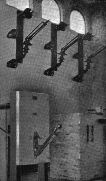
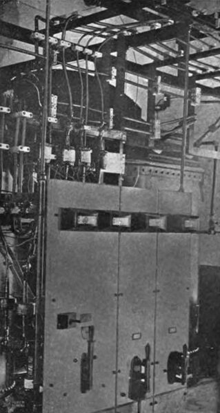
The interior of a typical sub-station is shown in Figs. 8 and 9, all the apparatus in view being of General Electric manufacture.
Reference has already been made to the lightning storms which are of frequent occurrence in the territory through which the transmission lines run, and every substation is, therefore, provided with a lightning arrester outfit. The experience of the Company in testing out various types of lightning arresters has resulted in the final adoption of the electrolytic aluminum cell type for all future installations, and there are already installed 22 sets of this type.
| |||
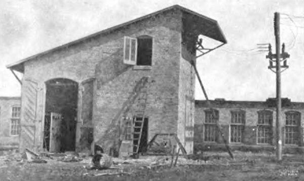
| Fig. 6. Bessemer City Transformer Substation Built to Accommodate Multigap Lightning Arresters |
| |||
| Fig. 7. Highland Park Substation, Charlotte, N. C., Showing Old Lightning Arrester Tower on Left, G. E. Aluminum Cell Lightning Arrester and Horn Gap in Foreground |
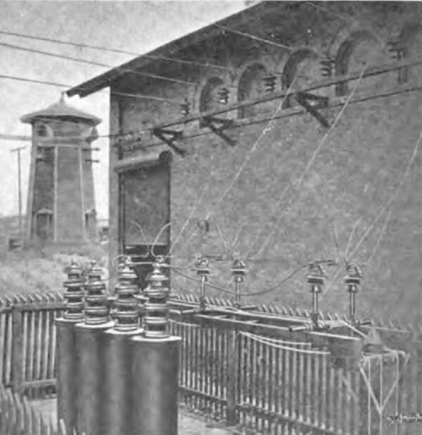
The illustration, Fig. 7, shows a set of General Electric electrolytic lightning arresters installed outside sub-station and the conductors entering the building through heavy plate glass windows, and also indicates one of the economies which the adoption of this type of arrester has made possible. When the multi-gap form of lightning arrester was first used, a high wall was provided on one side of the sub-station in order to provide sufficient space to suitably install them, the type of building used being shown in Fig. 6. It was later found advisable to discontinue this form of construction and erect a separate building in the form of a tower similar to that shown in the left hand of Fig. 7, in which the multi-gap arresters were installed. In view of the great number of sub-stations on the system, it is obvious that, with the adoption of the electrolytic type of lightning arrester, which can be installed out of doors, a very considerable item in the construction expense of substation buildings has been eliminated.
| |||
| Fig. 8. Interior of Kannapolis Substation Showing Conductors Entering Through Heavy Glass Plates G.E. K-6 Oil Switch and T.P. Fuses |
| |||
| Fig. 9. Interior of Kannapolis Substation Showing G.E. Transformers, Switches, Panels, Etc. |
The completion of the 100,000 volt lines and the construction of the new 100,000 h.p. hydro-electric plant at Wateree on which work has already been commenced will, at an early date, add appreciably to the range and volume of the greatest transmission system in the South, which is already one of the most extensive, in respect to aggregate mileage, in the world.
While the transmission line construction work has been characterized by few departures from standard practice, a comparison of the original 11,000 volt Catawba pole line with the 100,000 volt tower system, now nearing completion, gives a graphic illustration of the general advancement which has been made in transmission line construction during the few years which have elapsed since the Southern Power Company was organized. The success with which this Company has met the requirements of the cotton mills and other industries of North and South Carolina is indicated by the readiness with which mill operators have adopted electric drive and the very noticeable increase in the industrial activity of those sections of the Piedmont cotton belt where the transmission lines of the Southern Power Company have been run.
