[Trade Journal]
Publication: Electrical World
New York, NY, United States
vol. 57, no. 13, p. 781-783, col. 1-2
CONSTRUCTION OF UNITED STATES RECLAMATION SERVICE TRANSMISSION LINE IN ARIZONA.
ELECTRICITY generated at the Roosevelt hydroelectric station of the Salt River project of the United States Reclamation Service in Arizona is used partly for pumping water from wells in the Gila River Indian reservation and in Salt River Valley, south of Mesa, while the remainder is sold for industrial purposes at Phoenix. (See Electrical World, July 7, 1910.) When the plant is completed it will develop 4400 hp from a canal taking water at a diversion dam about eighteen and one-half miles above the storage dam and 5000 hp from the Roosevelt reservoir. A sixty-five-mile, 40,000-volt transmission line carries the energy from the station at Roosevelt to the Pacific Gas & Electric Company's plant at Phoenix. A branch circuit nineteen miles long is taken off at a switching station one and one-half miles northeast of Mesa and led to the pumping district south of Mesa and the Gila River Indian reservation.
| |||
| Fig. 1 - Transmission Line Leaving the Transformer House at the Roosevelt Dam. |
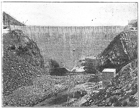
The transmission line consists of two three-phase circuits of six-strand, hemp-core copper cable the equivalent of No. 1 wire in cross-sectional area. The wires are fastened at the angles of a 4-ft. equilateral triangle and both circuits are carried on the same towers. The standard span is 400 ft. and the maximum 800 ft. One circuit is transposed one-third of a spiral every two miles and the other every four miles. At four points along the line, namely, at Bush Corral, Fish Creek, Tortilla Flats and Government Wells are towers fitted up so that by taking out a clamp the line may be opened for testing and repair.
The wires are carried from Roosevelt to the Highland Canal on rectangular, angle-iron braced, galvanized-steel towers made by the United States Wind Engine & Pump Company. On the towers there are four wires on the upper cross-arm and two on the lower. The cross-arms are made of channel iron. The towers on straight-way sections of the line are single-braced and those on angles are double-braced. On the steel poles there are four wires on the lower cross-arm and two on the upper. The cross-arms are made of a U-bar section similar to the rills of the pole and have diagonal braces and vertical struts between the two cross-arms to brace them.
| |||
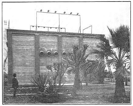
| Fig. 2 - Switching Station Near Mesa, Ariz. |
The line crosses the Salt River at Tempe in three spans of 800 ft. each. The two poles in the river bed are carried as steel cylinders 5 1/2 ft. in diameter filled with concrete Oar of them rests on bed rock and the other on hard pan at a depth of about 40 ft.
All towers in the section from Roosevelt to Goldfield are mounted on concrete bases or anchored in solid rock. The 418 towers in this section are from 15 ft. to 90 ft. high; fourteen are 5o ft. or more high and sixty-seven are double-braced and the balance single-braced. In the section from Goldfield to Highland Canal there are 192 towers 32 ft. high set on anchor plates about 2 ft. in diameter and buried from 4 ft. to 5 ft. in the ground. Tripartite poles, made by the Franklin Steel Company, 276 in number and practically all 30 ft. high, set in concrete one-tenth of their length, complete the line from Highland Canal to Phoenix.
A survey of the route of the line was made and a contour plan and profile drawn showing its relation to the road and other points of access for hauling purposes. The tower heights were chosen to give the minimum number and degree of vertical angles consistent with economical construction. The towers were ordered marked with the serial numbers of the locations, and were hauled and distributed according to a schedule furnished the commissary department of the Reclamation Service. With few alterations the towers were erected according to the numbers given. A few were shortened on one or more legs better to suit installation on the hillside.
| |||
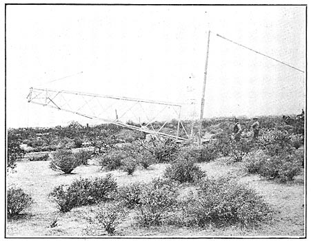
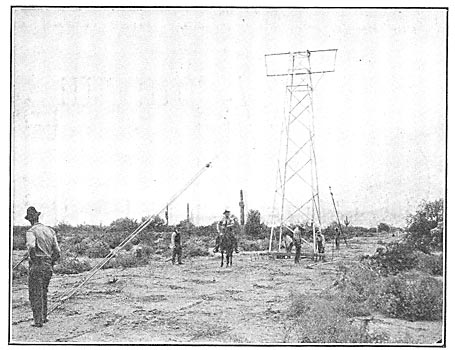
| Fig. 3 - Method of Raising Transmission Tower. |
A camp of from thirty-five to fifty men, mainly Indians, worked from Roosevelt toward Mesa excavating and concreting the tower bases, locating the anchor bolts by means of wooden templates. When this camp reached Weeks Station, eighteen miles from Mesa, it was separated into two camps, one going back toward Roosevelt setting up the towers and the other digging holes and setting the towers. When the towers and poles were up as far as the switching station, seventeen miles from Phoenix, a wire-stringing crew of twenty-three to twenty-five men worked toward Roosevelt stringing wire. The steel poles were erected by a separate crew which worked from the Highland Canal to Phoenix.
Where the lay of the ground would permit the towers were assembled on the ground and then raised into place with a gin pole. Where the ground was too uneven and rough they were assembled in position. A crew of six men erected an average of ten towers a day.
| |||
| Fig. 4 - View Showing Country Which Line Traversed. |
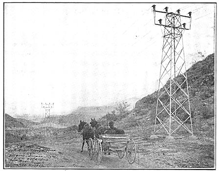
The erection of steel poles on this line was often delayed pending the adjustment of right-of-way difficulties, so progress was slower than it would otherwise have been. The average rate when working with a crew of twenty-two men was from eight to twelve poles a day. The holes were first carefully dug to the dimensions of the concrete bases. The poles, after being provided with cross-arms, were raised by a derrick on a wagon and set in the hole. Four guy cables were used and drawn up with light tackle and the pole brought into alignment by sighting with plumb lines located over reference stakes set by the survey party. The guys were then secured to steel stakes and the wagon was moved to the next pole. Concrete, mixed on a portable board, was then placed around the base and carried, by means of a piece of sheet iron used as a form, about 6 in. to 12 in. above the ground level to protect the pole from flooding. The top is pointed to a conical shape. After the concrete had set the guys were removed and used again. The piers at the river crossing at Tempe were sunk by an orange-peel bucket and then filled with concrete.
In stringing the wire on the level sections of the line in the valley it was drawn from the reels up over rollers on the towers and then pulled up to tension by horses. The wire all came in two-mile lengths and was strung the full length at a time. In the mountainous sections the wire was drawn in by means of a hoist mounted on a wagon, which carried two miles of 5/16-in. steel messenger wire. The messenger wire was carried from the hoist drum to the reels two miles away by mules and then the wire was pulled through. The messenger cable was then returned and the process repeated with each of the six wires.
The three-part insulators, shipped knocked down, were assembled in the field and the pins cemented by means of a special frame moved along with the stringing gang. The wire was tied to the insulators by two pieces of cable and two special brass clamps made for the purpose. A crew of twenty-three to twenty-five men made an average of seven miles per month in assembling the insulators and doing all work in connection with stringing the wire. The line was started July 4, 1907, and was tested Aug. 1, 1909.
After the wire was strung and before the energy was sent over it a crew of five men went over the line from one end to the other inspecting everything, tightening the bolts, cleaning insulators, replacing those that had been broken by the shots of hunters, putting in additional front and back guys that had been decided upon after stringing the wire, and making the line ready for service.
 |
| Fig. 5 - Bird-Guard Cluster to Hold Pointed Birch Rods. |
The first test showed no sign of trouble of any kind. After the line had been put into service it was found that a great number of short-circuits were caused at certain points by large hawks sitting on the towers and touching the wires with their wings or bodies. The wires were burned off several times and very bad service resulted, from the many interruptions. A guard (Fig. 5) was designed, consisting of a cast-iron cluster clamped to the tower at certain points and holding pointed rods of 5/16-in. birch doweling in proper position to prevent the birds from touching the wires. These were installed on the twenty-three miles of the line between Government Wells and the switching station, where 90 per cent of the trouble was experienced. Since placing the guards not one interruption in the section protected has resulted.
| |||
| Fig. 6 - Tower Being Bolted to Anchor at the Base. |
This transmission line has now been in operation for fifteen months, and in that time there have been no interruptions due to any defect of material or construction, no breakage of cables, no creeping of cables through tie wires, no broken guys, settlement or buckling of towers or poles of any consequence. Every interruption that has occurred on the transmission line has been the result of interference by birds, bailing wire thrown across the wires or the shooting of insulators by hunters. There have been two occasions where the wire itself has been broken by rifle bullets.
The tripartite steel poles used between Highland Canal and Phoenix are not galvanized, as are the towers, but are coated with a black paint. These poles were painted at the factory, but the erosion due to shipping across the continent and erecting was such that those not immediately painted showed much rusting after the first rainy season. All poles are now painted immediately after erection, and are expected to be good for from three to four years without further attention. The painting proves to be slow and costly, and there is little doubt that one or at the most two paintings will cost more than the additional cost of galvanizing.
| |||
| Fig. 7 - Connection Between Pole and Tower Line. |
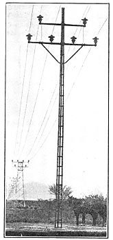
The single-circuit branch line from the Mesa switching station is operated at 40,000 volts. The wires are of the three-phase line placed at the angles of a 4-ft. triangle, the upper wire being on the top of the pole and the two lower ones on a cross-arm. The poles are standard tripartite similar to those on the main line, though they are lighter and have cross-arms for a single circuit. They are 45 ft. long except at road crossings, where they are 50 ft. The methods of construction were the same as on the level section of the main line. The rate of progress in setting poles was about twelve a day for twenty-two men. The stringing of the wire over the fifteen miles of line took three weeks.
This line has been in operation since April, supplying energy to a well-sinking outfit in the Indian reservation. The same trouble from hawks has been experienced on this line as on the main line, but it has been somewhat worse, on account of the small size of the wire, which burns off much more easily in case of a short-circuit. Guards for keeping the birds off will be installed on this line as soon as they can be obtained.
This work is in the Southern Division of the United States Reclamation Service, Mr. L. C. Hill, supervising engineer. Mr. A. H. Demrick, electrical engineer, was directly in charge of the construction until his death in May, 1909, when he was succeeded by Mr. I. C. Harris. The electrical development of the work was carried out under the technical direction of Mr. O. H. Ensign, chief electrical engineer, Los Angeles.
