[Trade Journal]
Publication: Transactions of the American Institute of Electrical Engineers
New York, NY, United States
vol. 30, no. 2, p. 1683,1734-1738, col. 1
TELEGRAPH TRANSMISSION
BY FRANK F. FOWLE
·
·
·
·
VII. IMPROVEMENTS IN LINE INSULATION
The minimum value of insulation resistance experienced in practice is a critical factor in fixing the required line conductance, as already pointed out. In order to show this more effectively the following Table XIX has been computed for a line of 10 ohms resistance per mile, assuming simplex transmission under the conditions previously described.
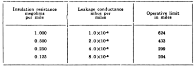 |
| Table XIX Effect of Varying Leakage on A Line of 10 Ohms Per Mile, for Simplex Transmission |
The table shows that the operative limit in miles increases slightly faster than the one-half power of the ratio of increase in insulation resistance; that is, quadrupling the insulation resistance increases the operative limit slightly more than double. The great saving in line cost which will result from better insulation is perfectly apparent and it is also apparent that the cost of better insulators may double or triple without materially reducing the saving if the gain in insulation is commensurate.
If the insulation could be increased indefinitely an operative limit would be fixed in any case by the inability to signal with requisite speed, but there is a large margin for improvement. For example, several cases have come under the author's observation where circuits of No. 8 B. W. G. iron, 500 to 600 miles in length, have been employed for through simplex or duplex service, without repeaters in good weather; upon the approach of heavy weather automatic repeaters were cut in near the middle of the line. If such a circuit measured 10,000 ohms in clear weather, it would require only 250 volts at each terminal to secure a line current of 0.050 ampere, which is well under the voltage limit for telegraph circuits in general, except composited telephone circuits.
There are two possible methods of improving the insulation. The first is the reduction of the number of poles per mile and consequently the number of insulators. In general this method is inapplicable except on lines carrying very few wires, because it requires greater sag in the spans, higher poles and increased horizontal separation between adjacent wires. The second method, which holds the greater potential possibilities, is the adoption of better insulators.
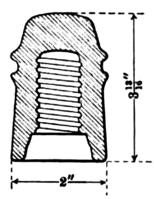 |
| Fig. 12. -- Standard Glass Insulator for Telephone Lines |
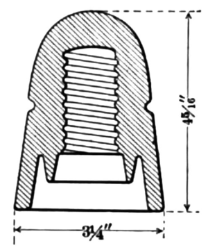 |
| Fig. 13. -- Standard Glass Insulator for Telegraph Lines |
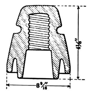 |
| Fig. 14. -- Porcelain Insulator for Loaded Telephone Lines |
Two types of insulators now in very extensive use are shown in Figs. 12 and 13. The first is the standard glass insulator for telephone service and the second is the standard glass insulator for telegraph service. A recent type of porcelain insulator for loaded telephone lines is shown in Fig. 14. The latter represents an effort to secure better insulation and is of special interest for that reason. It was learned some years ago, after the first attempts to load long telephone circuits of No. 8 B. W. G. copper, that the normal gain in transmission could not be maintained in heavy weather, because of the low insulation a result which was quite in accord with the full theory of the subject. In fact, when the insulation was very low, the loading caused an actual loss in transmission as compared with an unloaded circuit. The insulator in Fig. 14 is reported to give satisfactory results in the brief experience with it up to this time.
 |
| Fig. 15. -- Improved Type of Porcelain Insulator for Telegraph Lines |
These three insulators are all of the same general type, mounted on a pin, directly above and rather close to the cross-arm. In common they possess the disadvantage that the impact of heavy rainfall on the cross-arm tends to spatter the under sides of the petticoats and thus impair the insulation resistance. The insulator shown in Fig. 15 is designed to relieve this condition somewhat, but it is very difficult to do so without increasing the length of the pin and thus increasing the stresses in the cross-arm, at times.
 |
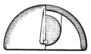
| Fig. 16. -- Under Hung Type of Porcelain Insulator for Telegraph Lines |
The possibility also suggests itself of adopting an under-hung insulator, of the pin type. Such a type is shown in Fig. 16; it seems to offer greater probability of a comparatively dry interior than any of the previous types. The large petticoat serves both to shed the water which comes from the cross-arm and shelter the interior. No water could reach the interior by impact or by spattering; if the line were on a hillside, a small amount of water might trickle down the line wire and wet the tie, but it would then drain to the under flange and drip to ground.
 |
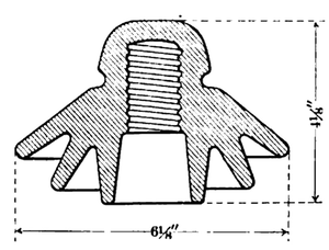
| Fig. 17. -- Strain Insulator |
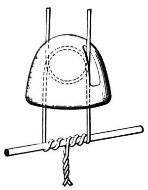 |
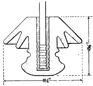
| Fig. 18. -- Strain Insulator, Showing Suspension |
 |
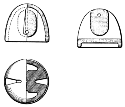
| Fig. 19. -- Strain Insulator |
It is but a step further in evolution to the more radical proposal for an insulator of the suspended or strain type, now familiar in power transmission. The insulator shown in Fig. 17 is dissimilar, however, from any of the present types for the latter purpose. It is specially designed to obtain as dry an interior as possible and consequently has an extended shell or petticoat. The suspension is of the link type, submitting the porcelain to compression stresses almost entirely. The hole for the upper suspension is made straight at the bottom so as not to hold water, which might otherwise collect and freeze, thus splitting the insulator by its expansion. As much room as possible is provided in the interior for the insertion of the lower suspension, between the shell and the bridge. Fig. 18 shows the general method of suspension and a particular method of attachment to the line wire. Fig. 19 shows the same general design with greater flare of the shell. This general type of insulator will only serve for tangent portions of a pole line, where all the stresses of the line wire lie in a vertical plane; at corners and curves the rigid suspension is necessary. It will permit slightly greater swinging of spans than ordinarily occurs with rigid suspensions and on that account it will be necessary to increase the horizontal separations slightly. In long tangents it will be necessary to introduce rigid suspensions for anchorage purposes, at periodic intervals.
The natural flexibility of this type of construction gives it some advantages under severe loads of sleet and wind. The breaking of a single conductor does not ordinarily relieve adjacent spans, but in this case it would do so for some distance and thus tend to prevent the complete stripping of wire which occurs frequently in severe sleet storms.
The strain type of insulator is better adapted to pole lines carrying a few wires than to lines heavily loaded, on account of the greater horizontal separation needed. At the same time, however, it can be used to increase the wire capacity of present lines, by stringing new circuits between arms. For special purposes, such as patrol circuits on or parallel to transmission lines, it also has advantages.
In general the proposal to change the types of line construction may seem radical to the telegraph field, which has been accustomed for so many years to fixed standards. But one of the greatest potential dangers in standardization lies in the fact that it may be overdone and given standards persisted in too long, at the sacrifice of progress and efficiency.
