[Trade Journal]
Publication: Engineering News
New York, NY, United States
vol. 65, no. 23, p. 694-696
Electric Traction in the Hoosac Tunnel; Boston and Maine R. R.
The work of installing equipment for electric traction in the famous Hoosac Tunnel, near North Adams, Mass., which has been operated under steam since 1875, has now been completed and electric locomotives have been put in regular service. According to press reports, the first regular trains were hauled by the electric locomotives on May 18.
It will be recalled that this tunnel was proposed as far back as 1825, though for a canal. In 1848, a charter was granted authorizing the construction of The Troy & Greenfield R. R. from the terminus of the Vermont & Massachusetts rm. R. at Greenfield, Mass., through the Deerfield and Hoosac Valleys to unite, at the Massachusetts-New York state line, with a road running into Troy, N. Y The project passed through many trials for the uncertain cost of the tunnel and the long interval before there could be any return on the capital deterred investors. Very little progress was made on the railroad and none on the tunnel up to 1854, when the company finally succeeded in having the State of Massachusetts pledge its credit for $2,000,000.
In 1855 and 1856 contracts were made with E. W. Serrell & Co., and some little work was done on the tunnel. These contracts became inoperative, however, because the railroad company was unable to float its stock. In 1856 a contract was made with H. Haupt & Co., and work was more vigorously prosecuted for a while.
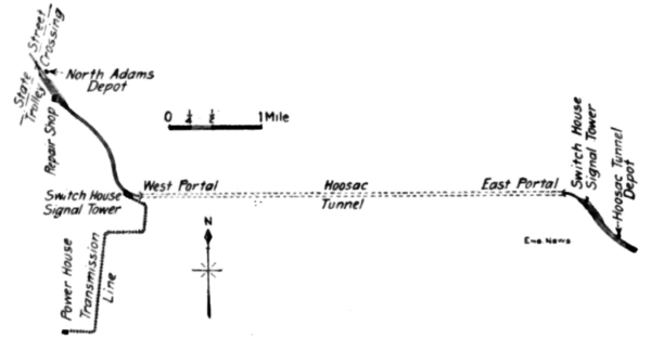
Up to 1861 only 4,250 ft. of tunnel had been constructed and in 1862 the state foreclosed its mortgages on the railroad property and completed the tunnel. The final headings were holed through in November, 1873, and the first engine was run through in 1875, though the first passenger train was delayed until October of that year, and the tunnel was opened for business in July, 1876. The Hoosac Tunnel is doubled-tracked and has a section about 21 x 26 ft. Its length is 25,031 ft., and the alinement is a tangent. The east ern portal is 768 ft. above sea level and for 2,000 ft. the grade is 0.35%. Then for 10,000 ft. the grade is 0.50%. In the middle there is 250 ft. of level stretch from which the grade descends, at 0.50%, to the western portal 765 ft. above sea level. The mountain pierced has two peaks with a valley between; the maximum height above the tunnel is about 1,800 ft. There were no high temperatures during the construction, and the flow of water was small. English bar timbering was used, the rock being mica schists and gneissesmostly hard.
 |
The advisability of using electric traction was considered by the Boston & Maine R. R., lessee of the Fitchburg R. R., in 1910, but it was not believed then that the time was ripe. When Mr. C. S. Mellen, President of the New York, New Haven & Hartford R. R. became President of the Boston & Maine also, in the same year, orders were given for the preparation of plans for electric traction, using the single-phase system in use on the New Haven lines. As the Haven Road at that time was engaged in the electrification of the New York, Westchester & Boston R. R. and the Harlem Branch an experienced supervising engineer was L. B. Stillwell, Past President Am. Inst. E. E. was offered and accepted the position to the Engineering Department of the New Haven.
Mr. W. S. Murray, Electrical Engineer of the New Haven Road, in a recent paper before the American Institute of Electrical Engineers, stated that general construction in the New Haven had become so fixed that most of the plans could be bodily transferred to the electrification of any trunk line service. To illustrate this, the Hoosac Tunnel construction after the New Haven plans was shown.
Some simplification and reduction in the weight of the locomotives has been secured through freedom from the complication of running over third-rail, direct-current lines, as in entering New York City. Five locomotives have been ordered for the tunnel service; three are intended for freight service and two for passenger trains, but the passenger locomotives will handle the lighter class of freight trains.
The only difference in designs is in the two designs is the gear ratios. Each locomotive weighs approximately 250 tons and is of the general quill-drive type with pony leading and trailing wheels, described in Engineering News, Oct. 7, 1909. The weight is spring supported and there are four main motors of 396 HP., normal hourly rating. These engines were built by the Westinghouse Electric Manufacturing Co., and the Baldwin Locomotive Works.
The use of 11,000 volts in the tunnel, with the small clearances there, brought problems in the location and support of insulators to prevent grounds. The construction worked out is shown in Figs. 5 and 6. Four 150,000-volt insulators are installed on a bracket, suspended from the crown of the tunnel. Two insulators serve the wire for each track, and they are electrically in series between the conductor and the grounded support, giving a combined dielectric strength of 300,000) volts. The outside insulator (Fig. 6) holds the main messenger cable, which is of copper strand, over the track. Two contact wires are hung side by side directly from this messenger cable. This last construction is the regular New Haven plan for limited clearances.
The extra high-potential insulators were used since the cost was only $1 per insulator more and the insurance against breakdown was increased eight times. The tunnel contains 1,000 insulators, so that the extra cost amounted to only $1,000 out of the total cost of $1,200,000 for the entire electrification.
The strain insulators used are those developed by the New Haven Road, shown in Fig. 9. Great progress has been made in the design and construction of such insulators to withstand continued mechanical and electrical stress. When the New Havens New York terminal electric zone was completed, in 1908, the best insulators that could be secured were rated at 7,000 lbs. and 40,000 volts and cost $27. By steady progress it has been possible to secure such an insulator to stand 110,000 volts and 35,000 lbs. simultaneously, with an ultimate strength of 60,000 lbs. The cost is $7.
The use of a copper messenger cable and the direct running of locomotive pantagraph shoe on the trolley wire are departures from the regular practice, which is seen in the yards at either end. There a 5/8-in. or 3/4-in steel catenary messenger cable (depending on span) supports a No. 0000 copper wire above a No 0000 phono contact wire. All fittings in the tunnel are of bronze for longer life where maintenance is more difficult.
In the tunnel approaches, 110,000-volt insulators have been used at an increased cost of $0.50. Each over the ordinary 40,000-volt type which would have been used ordinarily. This has been done in accordance with the endeavor to raise insulation to a point beyond the chance of break down and to eliminate line failures.
In the design of the power house at Zylonite, near North Adams, the plans developed for the Waterbury Station of the New Haven Road were used with slight changes needed to meet local conditions. Two 3,000 H.P. steam turbine generators are used, with provision for a third in case the traffic grows to warrant it. This power house is 2.4 miles from the track catenaries, this distance being needed to utilize an advantageous site.
On Nov. 1, 1910, work on the overhead line construction was started by the contractors, F. T. Ley & Co., of Springfield, Mass. A force of some 500 men were put on throughout the electric zone and the working hours were fixed at eight hours for the tunnel crews and ten hours for outside men. About April 12, the outside-work was practically completed and then two shifts were put onto the tunnel work.
The difficulties of this work have been great on account of the very heavy traffic which could not be stopped or much delayed. As there were one, and sometimes two, work-trains in the tunnel at a time, the regular traffic had to be carried on a single track. The gas and smoke from these regular trains made work difficult and slow, of course, and the conditions were made worse by the necessity of keeping a good head of steam on the work-train engines to develop power for drills, etc. Many men had to be brought to the portals for treatment for partial asphyxiation and a few had to be sent to the North Adams hospital. In all, three lives have been lost in the work.
The electric zone extends from a small tunnel, just west of the North Adams station, to a point just east of the Hoosac Tunnel station. All passenger trains stop at North Adams for the attachment or detachment of the electric locomotives. Freight trains on this side of the tunnel will change at a siding near the west portal. On the east side of the tunnel, passenger trains scheduled to stop at the Hoosac Tunnel station will change engines there. All freight and such passenger trains as are not scheduled to stop at the Hoosac Tunnel station will change to a point between the station and the portal.
