[Trade Journal]
Publication: Electrical World
New York, NY, United States
vol. 58, no. 1, p. 17-20, col. 1-2
STEAM AUXILIARY TO HYDROELECTRIC IN STALLATION.
An Outline Description of the Southern Power Company's Steam Stations.
BY J. W. FRASER.
IN the issue of the Electrical World dated March 24, electric generating stations, substations and trans 1910, the present author gave a summary of the hydro mission lines of the Southern Power Company in the Carolinas, together with a description of the 100,000-volt equipment which had then been in service for a short time. About a year ago the company determined to add 24,000 kw in steam apparatus to its existing generating equipment of 75,000 kw in hydroelectric apparatus. The steam-generating plants were intended to be used as auxiliaries to reinforce the hydroelectric stations at periods of low water and for emergency use in case of interruptions to service on the hydroelectric systems. It was considered advisable to divide the 24,000 kw of steam equipment into three units and locate plants at three large distributing points on the transmission system in order to save the line loss and in sure continuity of service.
| |||
| Fig. 1--General View of Greenville Station. |
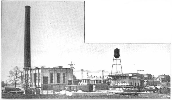
The station at Greenville has recently been put in service and the equipment is now being installed in a station at Greensboro. Construction work has not yet been started on the third station. As the plants were intended to operate for only from two to four months out of the twelve months, it was important to keep the first cost low. For this reason no economizers, automatic stoker or coal-handling apparatus was provided. However, arrangement has been made so that they can be installed if at any time in the future the plants have to be operated continuously for twenty-four hours per day.
 |
| Fig. 2--Map Showing Location. |
The description given below is based primarily on the Greenville station, although it is applicable almost in entirety to the Greensboro station, the differences being as noted later.
BUILDING.
The boiler-room is 196 ft. long by 49 ft. wide by 43 ft. high. The turbine-room is 90 ft. long by 38 ft. wide by 35 ft. high, with basement 17 ft. 2 in. A concrete foundation extends to the level of the turbine-room floor, where the steel columns which support the crane and roof trusses are carried. The steel columns are incased in brick pilasters which tie in the ends of the 9-in. curtain walls. The brick used is cast of concrete and is known as "unit brick" This brick has been used largely in the building of trans former substations and has proved very satisfactory. The roof trusses are spaced the same distance apart as the pilasters-that is, 15 ft-and the 3-in. splined sheathing is supported by 8-in. channel purlins spaced 6.5 ft. on turbine room and 8 ft. on the boiler-room. The waterproofing of the roof is of built-up tarred paper with gravel.
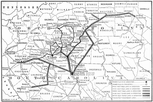 |
| Fig. 3--Map of Transmission Lines. |
The floor of the turbine-room has been extended only a few feet beyond the turbine in order that the pumps and heater may be accessible to the crane. Part of the floor is removable so that the crane can be used for unloading cars in the basement.
THE EQUIPMENT OF THE GREENVILLE STATION.
One 8000-kva, 60-cycle, 2200-volt, three-phase turbo generator set. One Westinghouse-Leblanc jet condenser for the turbine directly connected to non-condensing steam turbine.
One Westinghouse air pump directly connected to a 20-hp motor for service when the generator will be used as a synchronous condenser.
One steam-turbine-driven exciter set, 100-kw, 250-volt generator directly connected to one non-condensing steam turbine mounted upon a common bedplate operating at 240 r.p.m.
One motor-generator exciter set, 100-kw, 250-volt, compound-wound generator directly connected to one 150-hp, three-phase, 2200-volt motor, mounted upon a common bed plate.
One switchboard on which are mounted the necessary indicating and recording meters and control switches for operating the oil circuit-breakers.
Two 17-in. x 12-in. x 15-in. duplex outside center-packed plunger boiler-feed pumps, completely brass-fitted, with Tobin-bronze piston rods and solid-brass water plungers; output rating, 670 gal. per minute against a water pressure of 175 lb.
Two 10-in. x 14-in. x 10-in. plunger and ring low-service pumps, completely brass-fitted; output rating, 570 gal. per minute against a pressure of 75 lb. These pumps are for raising the water from the hot well to the heater.
One Cochrane feed-water heater.
One 400-gal. centrifugal tank pump.
One 10-in. centrifugal cold-well pump. This is a vertical pump placed in the bottom of the cold well and is connected to a vertical motor on the floor of the turbine-room basement for elevating the water from the cold well to the intake tunnel.
Two sump pumps.
Six 750-hp Erie City vertical water-tube boilers.
Six Foster super heaters.
One 230-ft. radial brick stack, 14 ft. inside diameter, lined 70 ft. high.
One 30,000-gal. service tank. One 14,000,000-gal. reservoir.
BOILERS.
The boilers used are of the two-drum vertical type. The lower drum is connected with the upper drum by 432 3-in. seamless tubes in twelve rows of thirty-six each. The furnaces are of the Dutch-oven type with long throats and have 132 sq. ft. of grate surface. The heating surface of the boilers is 6021 sq. ft. The guaranteed evaporation is 10.5 lb. of water from and at 212 deg. Fahr. When operating at 750hp, and10lb. of water at 1125 hp, per pound of coal containing not less than 14,250 thermal units and not more than7.5 percent ash. Three batteries of two boilers have been installed and space has been provided fora fourth battery when found necessary.
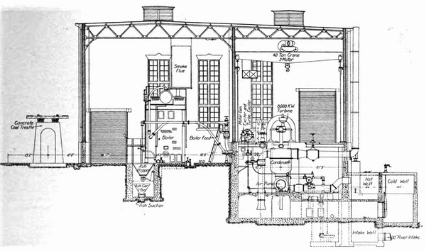 |
| Fig. 4--Cross-Section of Greenville Station. |
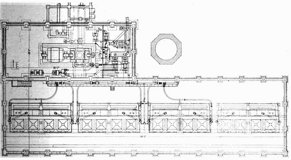 |
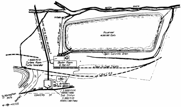
| Fig. 5--General Plan of Greenville Station. |
SUPERHEATERS.
The elements of the super heaters are made of seamless cold drawn sheet tubing fitted with annular cast-iron grill flanges close to each other. They are placed in front of vertical tubes of boilers and are accessible from doors in front of the boiler setting. Each superheater will increase the temperature of 22,500 lb. of steam per hour at a pressure of 160 lb. per square inchby100deg. Fahr. When the steam contains not more than 1 percent entrained moisture.
CONDENSING WATER.
The condenser requires 6,000,000 lb. of cooling water per hour to produce a vacuum of 28in. when the temperature of the injection water is 80 deg. Fahr. Under these conditions the temperature of the discharge water from the condenser is guaranteed to be within 4 deg. Fahr. of the temperature corresponding to the vacuum. With the injection water not exceeding 85 deg. Fahr. the condenser under the same conditions of load will develop 27.6 in. of vacuum. With the injection water not exceeding 90 deg. Fahr. the condenser under the same conditions of load will develop 27.25 in. of vacuum. The normal flow of the Reedy River, from which the condensing water is taken, is over 30 cu. ft. per second, which is ample for condensing purposes at normal load, but as this plant was built to be operated in periods of low water, and as the Reedy River runs as low as 20 cu. ft. per second, it was necessary to build a reservoir for storing the condensing water. This reservoir is 750 ft. long, 300 ft. wide and 9 ft. deep, and will hold approximately 14,000,000 gal. This reservoir has been made of earth embankments.
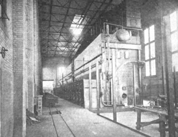
| |||
| Fig. 6--Boiler-Room. |
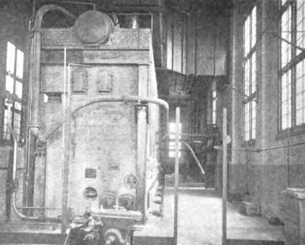
| |||
| Fig. 7--Boiler-Room. |
The water from the river flows by gravity through a 30-in. terra-cotta pipe to a cold well outside the building. This well is connected to another well inside the building by a pipe in which there is a valve that can be shut in times of flood water. The water from the cold well inside the building is elevated into the intake from the pond by a vertical submerged centrifugal pump driven by a motor placed on the basement floor. The pump and reservoir are in parallel so that all the cold water from the river runs directly to the condenser and only part of the water is supplied by the reservoir. The reservoir is connected with another cold well outside the building, from which is started the tunnel going to the condenser's suction.
When the plant is being operated ten hours per day at the low stage of the river the water in this reservoir will go once through the condenser in a week. As much water as is taken from the pond is returned to the further end of the pond in an open concrete flume, thus giving it a chance to cool before re-entering the reservoir.
COAL AND ASH-HANDLING EQUIPMENT.
Along the side of the building on which the boilers front a concrete trestle 16 ft. high has been built for coal storage. The center line of the trestle is 12 ft. from the building wall, in which openings have been provided to admit the coal. These openings are 4 ft. x 6 ft., and there are two of them per bay. The furnace fronts are set 14 ft. from the inside of the wall, so that no shoveling will have to be done to place the coal in position for firing when the bins are full. In addition a track for the firing cars has been provided. This track runs in front of the boilers and extends completely around the storage space, which will hold 2500 tons.
PIPING.
In placing the turbine, boilers, pumps, etc., an endeavor was made to arrange for a simple piping layout. A 12-in. main header is located on the rear boiler-room wall, to which connection is made from superheater nozzles by 7-in. leads with long bends. A 14-in. long bend connects the header and the separator, and the top of the latter is connected by a bend to the throttle valve. The pumps and heater are placed in the turbine end of the basement, making the length of all steam and water connections a mini mum.
The arrangement of valves is as follows: In the boiler leads are a 7-in. angle globe and a 7-in. horizontal non return valve. In the main connection is a 14-in. straight way gate valve. On the steam ends of the air pump, the exciter turbine, the heater pumps and the oil pumps are straight-way gate valves; on the exciter turbine are angle globe valves. Each pump is arranged to be operated independently of the other pumps.
All valves (including body, bonnet and yokes) and flanged and screwed fittings for high-pressure superheated steam are of crucible steel of extra heavy cast-iron pattern. The body and bonnet flanges of the valves are turned to give 1/32-in. raised seat inside of the bolt holes. The backs of the flanges are spot faced or fully turned. The stems and seats are of nickel steel. All pipe flanges for the high-pressure superheated steam lines of 5-in. size or larger are of the extra-heavy, high-hub, flanged and rolled steel Van Stone ring type, machine finished all over with 1/32-in. raised seat inside of the bolt holes. All pipe for the high-pressure superheated steam lines is of soft steel, full-weight standard lap welded, tested for 500 lb. per square inch.
PIPE COVERING.
All high-pressure superheated steam lines are covered with a 1-in. layer of special long-fiber asbestos cement, securely bound with a layer of 2-in.-mesh galvanized-wire netting, two layers each 1 in. in thickness of 85 per cent magnesia sectional covering applied so as to break both the longitudinal and the circumferential joints. All joints are filled with cement. A final 0.75-in. layer of special long-fiber asbestos cement was applied to the sectional covering, on top of which was sewed an 8-oz. canvas duck covering backed with resin-sized paper. Each flange is provided with a 2-in. removable covering.
The auxiliary steam piping is covered with 1.5-in. sectional covering and duck. On the high-pressure drip piping, boiler-feed and auxiliary exhaust the flange covering has been omitted. The feed-water heater, the cylinders of the boiler-feed pump and the exposed surface of the boiler drums are covered with 85 per cent magnesia blocks 1.5 in. thick and a layer of hard-finish cement. A covering of 8-oz. canvas duck is pasted and sewed on all of these surfaces. Each manhole and boiler drum, heater, etc., has a 2-in. removable covering.
TIE-IN TRANSFORMER AND SWITCHING STATION.
On the opposite side of the railroad track from the Greenville station there is an 18,000-kw transformer station which is used for reducing the emf from 100,000 volts to 13,000 volts or 2400 volts for local distribution. The generator of the steam station is connected to the 2400 volt busbars in this station and can be operated either in parallel with the high-tension transmission system or directly on a part of the local load.
GREENSBORO STATION.
This station is almost identical with the Greenville station except that the transforming and switching stations have been combined with the generating station. The two circuit, 100,000-volt trunk line from Great Falls will be switched here for Durham, and there are being installed three 3000-kw transformers to reduce the emf from 100,000 volts to 13,000 volts for power distribution and three 1000-kw transformers to reduce the emf to 2400 volts for city distribution.
