[Trade Journal]
Publication: Electrical World
New York, NY, United States
vol. 58, no. 11, p. 619-622, col. 1-2
NEW HIGH-TENSION TRANSMISSION SYSTEM IN CONNECTICUT VALLEY.
An important addition to the high-tension electric transmission system of New England has been in operation for about a year in the Connecticut Valley district of Massachusetts under the management of the Easthampton Gas Company and the Amherst Power Company. The enterprise includes the introduction of hydroelectric service into the Amherst. Easthampton and Mount Tom districts and the construction of an auxiliary steam turbine generating station and substation at Mount Tom Junction, from which facilities for power distribution throughout a wide area are available. A conspicuous feature of the work is the operation of a steel-tower transmission line 8.5 miles in length between Amher.st and Mount Tom, the line delivering energy purchased from the Turners Falls Power Company at 23,000 volts to the Easthampton Gas Company. The construction work of the enterprise has been handled by the local companies under the direction of Mr. H. Turner, supervising engineer, and the consulting engineer of the undertaking is Mr. N. J. Neall, of Boston, Mass., formerly of the firm of Thomas & Neall, New York and Boston.
| |||
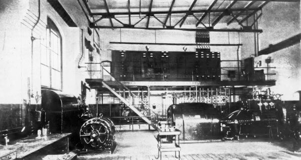
| Fig. 1 Interior of Easthampton Power Station. |
Prior to the establishment of the Mount Tom generating station and substation and completion of the steel-tower line from that point to Amherst energy was transmitted from the Turners Falls plant to Amherst by a three-phase circuit carried on a wooden-pole line, the distance being 18 miles. This line has been retained in the new development, the extension to Mount Tom Junction being carried on steel towers. The line has been designed for ultimate operation at a potential of 66,000 volts. The auxiliary turbine plant at Mount Tom Junction was installed in order to insure absolutely continuous service of adequate capacity, the amount of power available at Turners Falls being somewhat limited in view of the industrial possibilities of the Easthampton region.
The transmission line between Amherst and Mount Tom consists of ninety-three steel towers of the so-called Rockingham type and two river towers carrying the line across the Connecticut River at .Mount Tom to the generating station of the Easthampton Company, the latter being located on the west bank of the stream and connected with the local centers of distribution by a 4600-volt, three-phase service.
In the construction of the transmission line nine dead-end towers, five towers with 7- ft. extensions, one tower with a 14-ft. extension, and seventy-six standard towers were erected. One mile of pole line was built to connect the steel tower line with the old line in Amherst, and the 4600-volt service from Mount Tom station to Easthampton is 4 miles out. in length, wooden-pole construction being followed throughout.
| |||
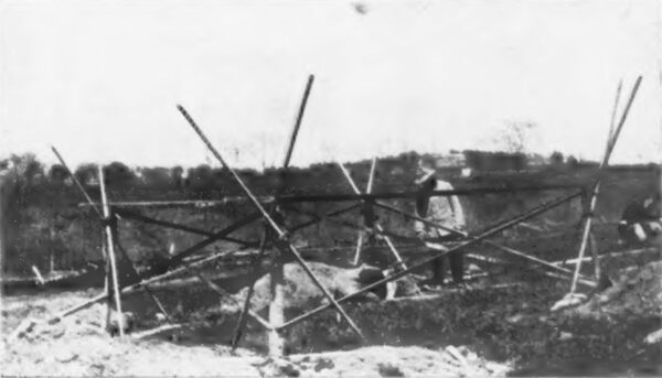
| Fig. 2 Method of Placing Steel Tower Anchors. |
The standard tower consists of an A-frame built of steel angles, the structure being 12 ft. square at the bottom and about 50 ft. high. In general, the vertical members are built of 3-in. x 3-in. x 3/6-in. angles, the horizontal members being as a rule of 2-in. x 2-in. x 1/8 in. angles, and the diagonal bracing 1-1/2-in. x 1-1/2-in. x 1/8-in. angles at the bottom and 1/2-in. round rods in the balance. The standard tower is built in seven vertical sections varying in height from 8 ft. to 6 ft. 2-1/2 in., and the tops are approximately 7 ft. in width. The standard height of the nearest conductor to the ground is 45 ft. 1 in. Each tower is surmounted by a 3/4-in. pipe 4.5 ft. long, carrying three 3/8-in. round rod lightning projections 2 ft. in length, A 7/16-in. steel ground wire is also carried from tower to tower above the transmission wires. The standard span between towers is 500 ft., and the maximum span, at the Connecticut River crossing, is 1200 ft. The line wire is seven-strand No. 2 B. & S. copper cable carried on quadruple-petticoated Thomas porcelain insulators 14-7/8 in. in height, which are spaced on a 6-ft. l0-1/2-in. equilateral triangle.
The towers are anchored in concrete or earth foundations, according to the nature of the soil encountered. The towers were assembled on the ground, rights of tower location having been purchased from landowners. They were erected by the use of gin poles, a force of twelve men usually being required. The maximum number of towers erected in a single day was fourteen, the contractors for this work being Messrs. Fred T. Ley & Company, Springfield, Mass. The tower anchors were located by the use of adjustable templates built of angle irons and round rods, as shown in the accompanying illustration. In the location of the anchors holes were first excavated at the approximate corners of the tower. Planks were then laid across the holes in a diagonal fashion and the template was lined up against the timbers and leveled. The anchors were then attached to the template at the corners and the holes backfilled or concreted. The templates were then removed and the towers attached to the anchors.
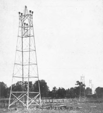 |
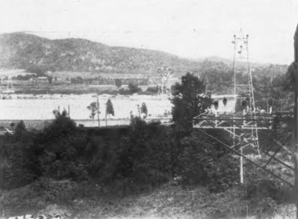
| Fig. 3 Transmission Line With Dead-End Tower in Foreground. |
 |
| Fig. 4 Mechanical Connector at River Crossing. |
The dead-end towers are provided with slightly heavier angles than the standard structures and are also equipped with two pins, one on each side of the tower, carrying each phase wire. Two transpositions were made in the line between Mount Tom and Amherst. All joints in the wire; were made with McIntyre connectors and a telephone circuit of l4-in. steel wire is carried on the towers about 10 ft. below the transmission circuit and transposed at every tower. The insulators are carried on pins composed of 2-in. extra heavy pipe. On account of the variations in the height of the water in the Connecticut Valley, particularly in the lowlands bordering the river near the crossing of the line from the east to the west bank, the towers near the shore are provided with a foundation facing of concrete 5 ft. in height to protect the structure from floating ice.
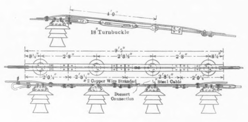
The river crossing is supported by two dead-end towers carrying the conductors 60 ft. above the ground, the base of the tower being 18 ft. square in each case. In place of copper the span across the river consists of three special Siemens-Martin steel cables 1/2 in. in diameter each. The cables were cut to length and pulled to the proper sag by the use of turnbuckles, the construction being shown in the accompanying drawing. The top of each river crossing tower is equipped with an angle-iron framework carrying four insulators in a single row for each phase wire, but in place of the wire the insulators carry a steel plate clamped to their tops, the plate tying the four insulators together in each phase and being provided at each end with a turnbuckle 18 in. in length to which the phase cable is clamped.
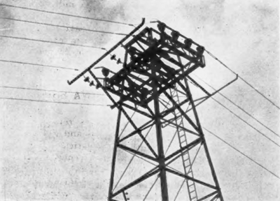 |
| Fig. 5 River-Crossing Tower. |
The insulators are spaced 2 ft. 8 in. apart in seriatim the supporting strap is supplemented by carrying the conducting steel cable to approximately the middle point, joining the cable to the No. 2 line wire by a Dossert connector. The strap is 4 in. wide and 1/2 in. thick and is bolted to the clamps which surround the insulator heads, as shown in the accompanying photograph made before the copper and steel line wires were joined. Each river tower is equipped with a grounding bar installed on each side of the structure and the conductors are each tied into the tower by three strain insulators, so that in case of a break in the line at the tower the phase in trouble will immediately be grounded.
| |||
| Fig. 6 Transmission Line Crossing River. |
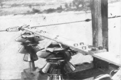
The standard attachment to the insulator employed on the line is shown herewith, and it consists of a double helical tie of No. 4 copper on each side of the insulator, making two pairs of loops around the insulator cap. The main conducting wire is carried across the top of the insulator through a porcelain bushing, and just outside the bushing on each side the helical tying is begun and continued for a distance of 6 in., the end on each side being carried completely around the groove in the insulator head and continued down the phase wire away from the insulator for 6 in. more, so that the total length of tie wire is 12 in. on each side of the insulator.
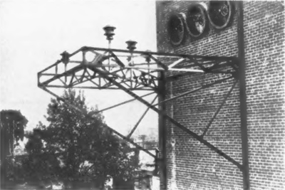 |
| Fig. 7 66,000- Volt Entrance Bracket. |
The generating plant and substation at Mount Tom is a structure of brick, concrete and steel located beside a spur track of the Boston & Maine Railroad and within about a hundred yards of the river. The generating station proper is about 90 ft. long by 70 ft. in width and at the east end of the building is located a substation or transformer room 40 ft. X 25 ft. in plan. A boiler room 67.5 ft. X 47 ft. and a turbine room 57.5 ft. x 40 ft. in dimensions divide the power plant into two fireproof sections, temporary walls being left on the north side of the station to provide for future increases in capacity. Beneath the boiler and turbine rooms is a basement about 20 ft. high containing condensing and pumping equipment, turbine foundations and piping. The transformer house is built in two stories with a 7.5-ft. basement containing a tank and piping for cooling water service. Coal is brought to the plant by rail and delivered into a temporary storage bin at the west of the boiler room, provision for weighing it in hand barrows being made in front of the furnaces. Two 350-hp Heine water-tube boilers furnish the steam supply, these being operated at 160 lb. without superheating. The exhaust gases of the boilers discharge through short tapering uptakes into a breeching leading to a Custodis radial brick stack 145 ft. high and 8.5 ft. in inside diameter. The stack foundations are carried down to bed rock at a depth of 12 ft., the base of the foundation being 17 ft. square. In general the station foundations are carried to bed rock, piles being used only in cases where the rock was over 12 ft. below the surface of the ground, and the basement walls are thoroughly waterproofed. Where piles are used they are capped with concrete reinforced by old steel rails to prevent any cracking of the foundation where the concrete rests on the rock in case of pile settlement. Outside walls are of brick, the thickness being 16 in. The boiler house and turbine room are provided with a concrete roof supported on steel trusses and the transformer house is furnished with a similar roof carried on steel I-beams.
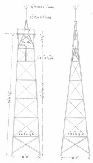 |
| Fig. 8 Standard Type of Tower. |
Water for boiler-feed and condensing service is drawn from the Connecticut River by a 12-in. x 15-in. x 15-in. Worthington duplex low-service steam pump, there being a 14-in. pipe 700 ft. in length between the stream and a well located just without the turbine-room doorway. The pipe connections provide for the delivery of feed water to a 1500-hp National closed heater which raises the temperature to 200 deg. Fahr. before the water enters the boilers. The heater is by-passed and it delivers water to a 6-in. feed main running along the boiler fronts, from which risers lead to the steam generating units. From the boilers 6-in. steam delivery outlets connect with a 15-in. header from which branches lead to the turbine and auxiliary apparatus. A l0-in. x 6-in. x l0-in. Warren feed pump handles the boiler water supply.
The present generating unit consists of a 1000-kva Westinghouse turbo-alternator delivering three-phase, 60-cycle energy to the busbars of the station at 4600 volts, the turbine being of the three-stage type, with a normal speed of 3800 r.p.m. It operates on a vacuum of 29 in. and the governor is equipped with a motor control for the purpose of synchronizing the machine more readily with the incoming service from Amherst. The speed can be varied about 200 r.p.m. by the governor control, which is operated by a 1/10-hp, 125-volt Westinghouse direct-current motor. Energy for this machine and for the alternator fields is supplied by two exciters, one being a 50-kw machine direct-driven by a 75-hp, 440-volt induction motor running at 2500 r.p.m. and the other a 50-kw turbo-exciter running at 2250 r.p.m. The latter machine is equipped with fan cooling apparatus and the generator winding is of the interpole type. The turbine is provided with a supply of air for cooling the generator through a duct carried under the floor from an opening in the north wall of the building. The turbine exhausts into a Westinghouse LeBlanc condenser located directly under the unit in the basement. The condenser is provided with an 8-in. discharge line to the river and takes injection through a 10-in. line connecting with the exterior well above mentioned. For starting the unit water for injection can be drawn from a tank located on the power-house roof, a 6-in. lead connecting with the condenser. The condenser air pump is driven by a Westinghouse steam turbine, which is operated at 1500 r.p.m.
 |
| Fig. 9 Conductor Attachment at River-Crossing Tower. |
Condensation from the local steam-heating system of the plant, which is served by the boilers through a reducing valve, is collected in a 200-gal. tank in the basement and thence returned to the boilers via the feed pump and heater. Other auxiliaries located in the basement include a 3-in. x 2-in. x 3-in. duplex turbine oil pump; a centrifugal sump pump driven by a 2-hp motor controlled by float switch, and two Kenney centrifugal pumps drawing water from eight driven wells for general plant service, each pump being driven by a 5-hp, 110-volt General Electric induction motor running at 1800 r.p.m. The motor starter for the roof-tank service is located on the switchboard gallery in the turbine room and mechanically connected to a float switch in the tank. The general service pumps are directly piped to the roof tank. The turbine room is served by an 8-ton Maris crane and a Peerless hoist of the same capacity is installed in the transformer room.
The incoming phase wires from the Amherst power system are brought into the substation through 36-in. Akron type bushings and after passing through disconnecting knife switches and choke coils the leads terminate in three 66,000-volt solenoid-operated oil switches located on the second floor of the substation. From this point the leads drop to the high-tension terminals of three 500-kw Westinghouse transformers of the water-cooled type, located on the ground floor of the building. These reduce the potential from 22,000 volts to 4600 volts and deliver energy to a busbar installation in the turbine room which is arranged to permit the separate operation of the steam and hydroelectric service if desired, although normally the two services arc handled in multiple. The switchboard is mounted 10 ft. above the floor of the turbine room. It is of the remote-control type, energy being supplied for the operation of solenoid oil switches by the turbine exciter units. The height of the turbine room is 28 ft. and in the section directly below the switchboard are located the oil switches controlling the 4600-volt distribution and bus circuits of the system. The transformer house is 51 ft. in height and it is connected with the bus structure in the turbine-room by cables run in conduit. The high-tension conductors enter the substation from the steel tower line with a spacing of 48 in. apart on centers. The substation is separated from the generating plant by fireproof doors and the second floor is reached by an iron stairway.
 |
The switchboard is located on a reinforced concrete gallery and contains sixteen panels controlling the various machines, high and medium tension switches. The usual power-factor indicator, frequency indicator, voltmeter, ammeter, regulating and recording equipment is installed. A bus-junction panel is provided which enables the steam and hydroelectric services to be paralleled after the usual synchronizing. Each feeder panel is equipped with an ammeter induction wattmeter and overload relay connecting with the 4600-volt oil switches on the floor below. The switchboard is lighted effectively by eleven 16-cp incandescent lamps mounted in a horizontal tin-lined reflector hung by wrought-iron pipe about 10 ft. above the gallery floor. House lighting and small motor service is supplied through three 5-kw transformers distributing energy from a cabinet situated on the switchboard gallery near the operating desk. By means of a double-throw switch the house lighting can be thrown upon either direct or alternating-current service at 110 volts, providing an emergency means of illumination in case of trouble on the alternating-current systems.
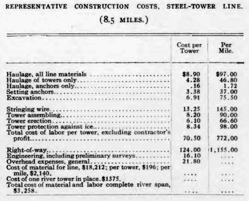
The West Boylston textile mills are the largest consumers of the company's service at present, but it is anticipated that a substantial increase in the amount of manufacturing in the vicinity of Easthampton will result from the introduction of the companys power. The Easthampton company distributes energy in the community within radius of the station, and the large textile mills above mentioned will shortly double their capacity. The accompanying selected cost data have been obtained through the courtesy of the engineers in charge of the design and installation of the high-tension line.
