[Trade Journal]
Publication: Electrical World
New York, NY, United States
vol. 58, no. 18, p. 1057-1060, col. 1-2
THE FIRST 110,000-VOLT INSTALLATION IN EUROPE.
Details of Lauchhammer Transmission System for the Supply of Electric Power to Rolling Mills.
Steam Generating Plant Located at Coal Mines.-Duplicate Conductors Installed on Single-Tower Line.-Slender Tower Construction.
BY KURT PERLEWITZ.
THE first 110,000-volt transmission system in Germany is now being installed and will be ready for operation in November. It is being built for the Lauchhammer Aktiengesellschaft, which owns large iron works at Lauchhammer, Gröditz, Riesa and Burghammer and also large coal mines at Lauchhammer. On account of enlargements of these works in recent years and the building of electrically operated rolling mills the present power supply was found insufficient and it was decided to build a large generating station from which all the works were to be furnished with electrical energy through high-tension transmission. Fuel for the generating station is to be furnished from the coal mines at Lauchhammer.
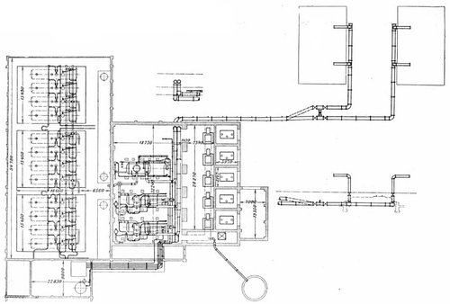 |
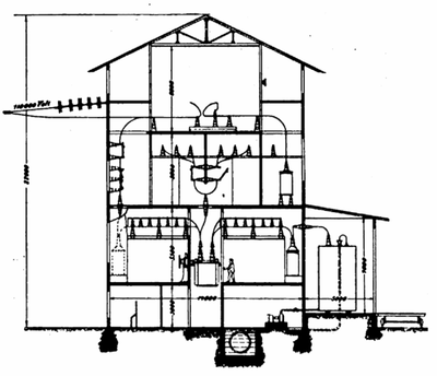
| Fig. 1--Plan of Generating Station at Lauchhammer. |
Besides the demand of approximately 6600 kw from its own works the plant is to furnish energy for a large portion of the province, containing four towns, 658 villages and 164 large estates, the demand of which is at the present time approximately 6000 kw. According to the estimates. there will be connected immediately more than 116,000 incandescent lamps and over 21,500 hp in motors. ultimate demand being calculated to aggregate about The 20,000 kw, it was decided to transmit the energy at a tension of 110,000 volts. The distance of hardly 35 miles did not require such a high voltage, but the large load to be carried and the fluctuation of voltage to be expected through the rolling-mill load would have made a lower voltage uneconomical. The selection of the voltage was also influenced by the question of insulators, transformers and switch gear, which had to be of special design for any tension over 65,000 volts. Therefore, it would make little difference in regard to cost of apparatus and appliances whether an 85,000-volt or a 110,000-volt system was decided upon, while with the latter voltage it would make a considerable saving in cost of copper. A pressure of 65,000 volts requires a conductor of 0.186 sq. in. cross-section, while 85,000 volts and 110,000 volts only require a copper cross-section of 0.11 sq. in. and 0.065 sq. in., respectively.
GENERATING STATION.
The plant at Lauchhammer, shown in Fig. 1, consists of boiler-room, engine-room and switchroom. The dimensions in this and other illustrations are all given in millimeters. The boiler equipment will consist of eighteen double-flue boilers, of which only twelve are installed at present. Each boiler will have 1600 sq. ft. of heating surface and be provided with superheaters. Use will be made of automatic stokers, for which the Lauchhammer coal is particularly well adapted.
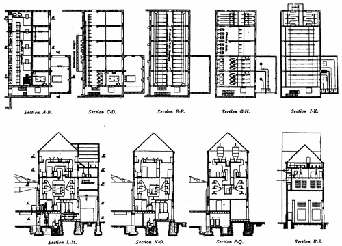 |
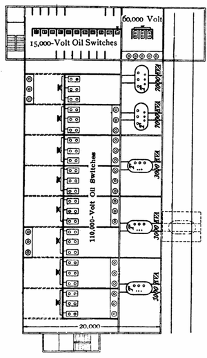
| Fig. 2--Elevations and Sections of Switch House at Lauchhammer. |
The feed water is heated in economizers. Instead of smokestacks the Schwalbach suction-draft system is used. Each group of four boilers forms one unit and each unit is provided with one 50-hp motor for the fans. The generating equipment will consist of four turbo-generators, of which three are being installed. Each generator is a three-phase machine designed for 5000-kw output at a power-factor of 0.8 and an emf of from 4740 volts to 5500 volts. Two of these sets were made by the Allgemeine Electricitäts-Gesellschaft and one set by the Maschinen fabrik Augsburg-Nürnberg, together with the Siemens Schuckertwerke.
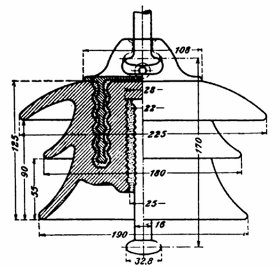 |
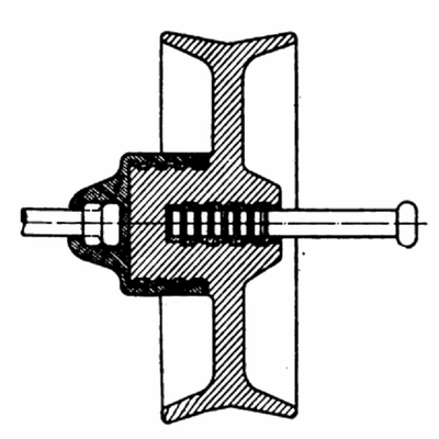
| Fig. 3--Suspension- Insulator Unit. |
 |
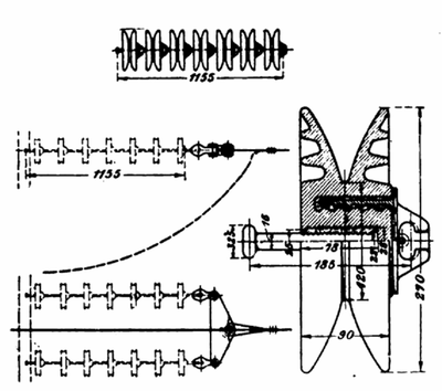
| Fig. 4--Strain Insulator on Curve of Transmission Line. |
From the generators the energy is transmitted through cables to the 5000-volt main busbars in the switch house. The busbars are in duplicate and are provided with disconnecting switches so that one set can be cut out without causing disturbance. There are joined to these buses two T-connected transformers with a secondary emf of 1450 volts, at which voltage about 1000 kw will be delivered at the Lauchhammer works. Connected to these buses are also four 6250-kva, three-phase transformers from which the energy is delivered to 110,000-volt busbars, which are also furnished in duplicate. On both sides of the trans formers are installed disconnecting switches and oil switches, the latter being electrically operated and controlled from a central switch panel. In the outgoing high-tension lines are installed disconnecting switches, oil switches, choke coils and lightning arresters, as illustrated in Fig. 2. The switch gear and transformers were made by the Siemens-Schuckertwerke.
TRANSMISSION LINE.
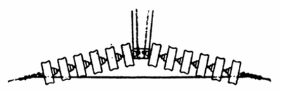
The conductors, which are installed in duplicate, are carried on one line of iron towers set in concrete foundations. The one-line system of towers was adopted on account of the difficulty of securing rights of way for two separate tower lines. The towers are of steel lattice-girder construction. Each conductor is of seven-strand, hard-drawn, electrolytic copper of approximately 83,000-circ. mil cross section. The spans are from 500 ft. to 650 ft. and the height varies from 60 ft. to 65 ft. A noteworthy feature is the span across the River Elbe, which has a length of nearly 900 ft., the height of the towers being 140 ft. and 120 ft. For this span various kinds of conductors were considered, such as stranded steel cables, copper wire with steel core, bronze wire and others, but careful calculations showed that pure electrolytic, seven-strand, 140,000-circ. mil copper cable would prove best for carrying the maxi mum load of ice and snow, the calculation being based on a factor of safety of five. Five-unit suspension insulators, made by the Porsellanfabrik Kahla, in Helmsdorf, are used on all intermediate towers. At crossings of streets, rail ways, rivers and certain other places use is made of two 6-unit strain insulators made by Rosenthal, in Selb, Bavaria. All conductors are carried on one pole line and each set of three conductors forms an equilateral triangle, the sides of which are 5.9 ft. For this purpose the upper cross-arm 1780 is bent, as shown in the accompanying illustration. Under each conductor is a ground connection in the shape of a bow supported on cross-arms, as shown in Fig. 7. This bow serves the purpose of catching and grounding the conductor in case the insulator should break. At the top of the tower is a 100,000-circ. mil steel ground wire, serving the double purpose of anchoring the intermediate towers and protecting the line against lightning. There are thus two systems of grounded connections at each tower. In order to prevent inductive disturbances the wires are completely transposed once in every mile, or altogether over thirty times. This arrangement not only eliminates the inductive effects on neighboring telephone lines, but also prevents mutual induction and electrolytic influence of the two parallel circuits. It will be noticed that, by the bow shaped form at the upper cross-arm the conductors are hung symmetrically, and inequality in the self-induction of the phases is thus prevented. This arrangement was de vised by Professor Ulbricht.
 |
| Fig. 5--Strain Insulator. |
 |
| Fig. 6--Strain Insulator Used at Crossing of River Elbe. |
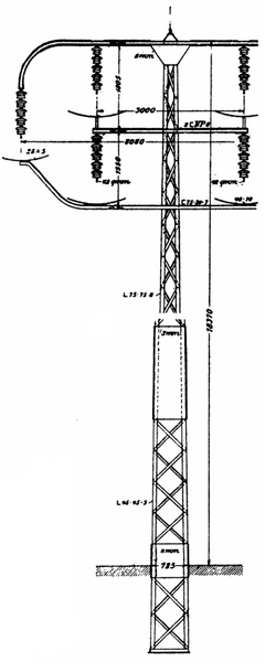 |
| Fig. 7--Intermediate Tower. |
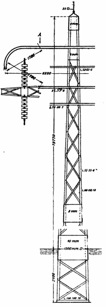 |
| Fig. 8--Straight Tower. |
At the crossing of the River Elbe two double sets of strain insulators have been used, as shown in Fig. 6. In regard to the protection of the stations against high-frequency disturbances advantage was taken of the experiences gained at similar installations in America. Ground resistances are installed in all outgoing lines and between bus bars, choke coils and horn-gap lightning arresters. Static dischargers are connected at the neutral point of the high tension winding of the instrument transformers voltage regulation of the system is effected by Tirrill regulators in the main station and also by regulating transformers on the 15,000-volt side in the main transformer station, which allow a variation of 750 volts.
SUBSTATIONS.
The substation at Gröditz, the arrangement of which is shown in Figs. 9 and 10, comprises an installation of three 3000-kva transformers and two 7000-kva transformers, the former stepping down the emf from 110,000 volts to 15,000 volts and the latter stepping down from 110,000 volts to 60,000 volts. Besides being connected through the 110,000-volt line the substations at Gröditz and Riesa are also connected through a 60,000-volt line covering the districts served by these stations.
 |
| Fig. 9--Section of Substation at GröDitz. |
 |
| Fig. 10--Plan of Substation at GröDitz. |
The stations are so arranged that any of the two can furnish energy for the whole district in case of a breakdown of the other. This arrangement also eliminates reserve transformers. The consumers are served from five transformer stations on this line, each distributing energy at 15,000 volts.
The design of the installation was made by Mr. E. G. Fishinger, Dresden, who also supervised the construction work. The illustrations accompanying the present article have been reproduced from an article by Mr. Fishinger which appeared in the Elektrotechnische Zeitschrift.
