[Trade Journal]
Publication: Electrical Review and Western Electrician
Chicago, IL, United States
vol. 59, no. 23, p. 1119-1125, col. 1-3
New Hydroelectric Development in Canada.
City of Winnipeg Completes Comprehensive Municipal System.
In 1905 the citizens of Winnipeg, dissatisfied with the prices charged for power and light, decided to create competition by building a municipal plant. With this end in view, they engaged a firm of engineers to make a report on the available sources of hydroelectric power on the Winnipeg River. A careful study of the hydraulic resources of the river was made, as a result of which the site at Point du Bois was chosen and estimates made of the cost of the work. A report was submitted to the City Council resulting in a by-law being submitted to the electors who by a large majority heartily indorsed the proposition.
| |||
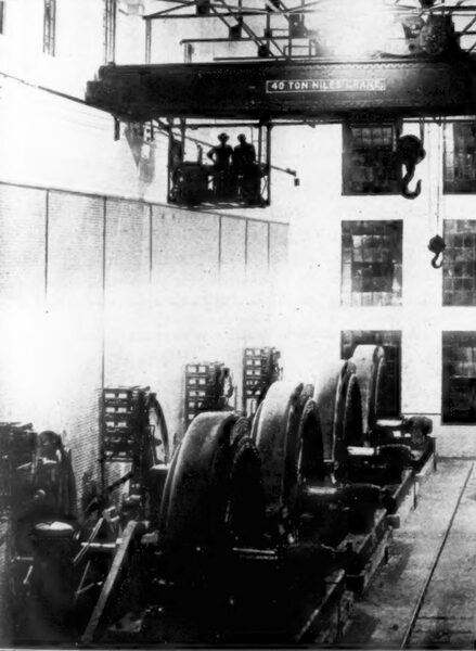
| Generator Room. |
| |||
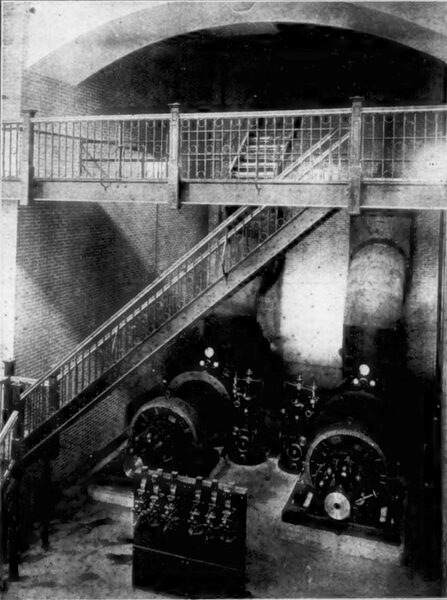
| Turbine Room. |
In October 1906, designs were begun and tenders were called for, but owing to the financial stringency existing at that time, the scheme was postponed. In the meantime, however, small sums of money had been appropriated for the building of a short length of tramway extending from Lac du Bonnet, the terminus of the Canadian Pacific Railway, to Point du Bois, the site of the plant, a distance of about twenty-six miles. In 1908 this line of railway having been completed and the financial clouds having cleared away, a start was made by awarding the contract for the construction of the plant and the erection of the transmission line. Since this time the work has been pushed continuously and the plant is now in operation.
The Winnipeg River drains an area of about 52,000 square miles, the country being of the Laurentian character covered with forests, which have so far been untouched by lumbermen. The basin is made up of countless lakes, marshes, swamps and muskeg, with the result that the river presents ideal conditions for development due to its rocky formation and uniform conditions of flow. The fall of the river from its mouth to its source in the Rainy River district is 347 feet, of which 185 feet are available for the development of energy in territory contiguous to Winnipeg.
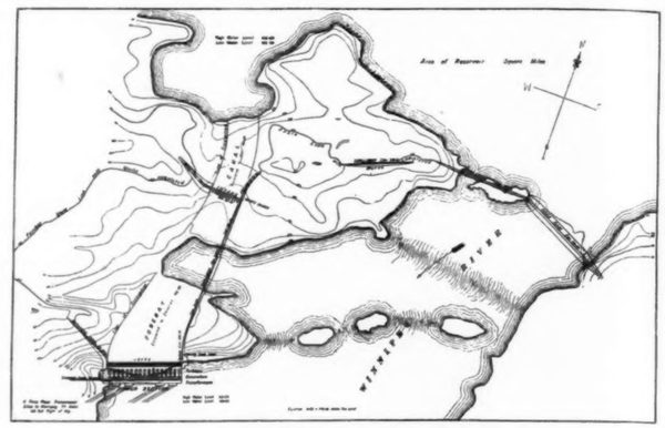 |
| Plat of Winnipeg Development. |
The Point du Bois Falls formerly had a natural fall of about thirty feet, which is now increased by the development to forty-five feet through damming the river and drowning out Lamprey Falls, eight miles above. The minimum flow of the river here is about 16,000 cubic feet per second, corresponding to a development of approximately 60,000 horsepower for twenty-four hours. The hydraulic features of the development have been designed for this amount, but the machinery at present installed will develop only 26,000 horsepower. A plat of the development is shown on the next page.
Briefly the plan has been to dam the river by means of a concrete spillway and a rock-fill dam taking advantage of the islands and shoals in the river. As this country is of a granite formation, no difficulty was experienced in finding good foundations. The water is diverted to the power house on the west side of the river by means of the dam leading into the forebay. This forebay is controlled from the intake and the water may be drained from it by using stop-logs, thus cutting off the water at the intake and opening the butterfly gate valve close to the power house.
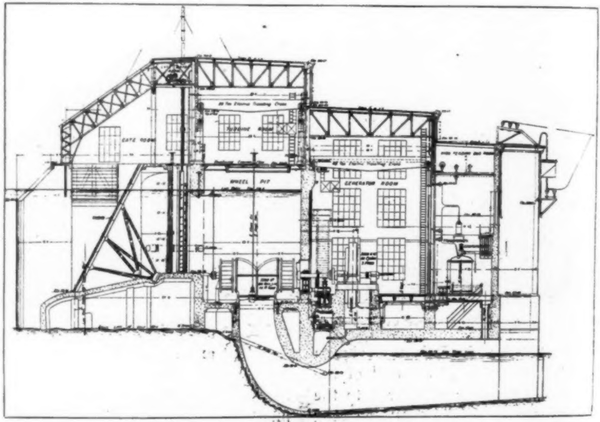 |
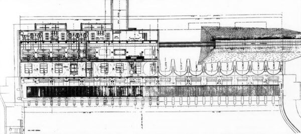
| Section Through Power Station. |
The power house is built of concrete throughout, being about 250 feet long, 150 feet wide and 100 feet high. Herewith are typical sections that show the general arrangement of apparatus. The water enters the turbine room through racks built over an apron of reinforced concrete. Each turbine is in a separate pit of circular cross section, the separating walls being of heavily reinforced concrete. Each turbine can be entirely isolated from the others by utilizing either the stop-logs or the motor-operated head gates. The head gates are of steel framework sheathed with pine and running on rollers. They are opened or closed by means of a rack meshing into a floating pinion on a shaft operated from the room above by induction motors.
| |||
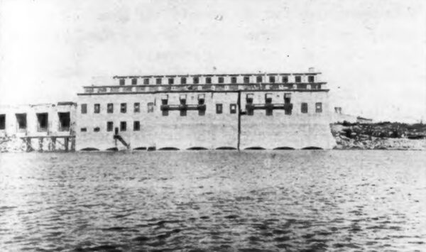
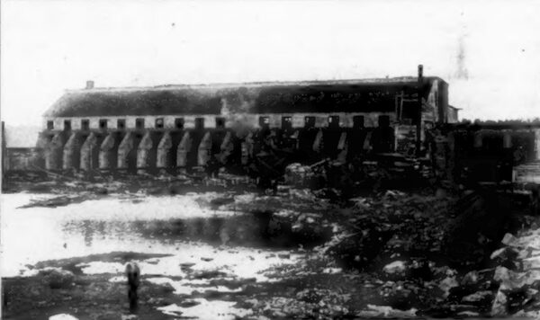
| Power House From Tailrace. |
| |||
| Power House From Forebay. |
The turbines, five of which are now installed, are of the horizontal double-runner type, of a capacity of 5,200 horsepower under full gate, at 164 revolutions per minute, operating under a head of forty-five feet and using 1,250 cubic feet of water per second at maximum output. They develop their maximum efficiency at seven-eighths gate corresponding to a full load on the generators. The draft tubes are of concrete, circular in cross section and gradually increase in size towards the outlets, giving at the turbines a water velocity of eight feet per second while at the seal of the draft tube the velocity is only 3.3 feet per second. The manufacturers guarantee the maximum efficiency of the turbines to be at least eighty-five per cent. The front bearing has ring lubrication, but the middle and back bearings are fed with forced grease lubrication from the generator room. The governors controlling the turbines are placed between the generators and the wall separating the generators and the turbines.
Direct connected to the turbines are the generators of 3,000-kilovolt-amperes capacity at 6,600 volts, sixty cycles. The machines are very strongly built, the rotors being of cast steel with a one-piece rim and four-piece hub shrunk together with steel rings. The windings are of formed coils in open slots, three slots per pole. The guaranteed characteristics of the machines are 95.2-per cent efficiency at full load; 8.25-per-cent regulation at 100-per-cent power-factor; thirty-five degrees centigrade rise in temperature at full load and unity power-factor. The motor-operated generator rheostats and field switches are mounted on the wall above the governors. The exciter bus bars run under the floor from the exciter switchboard to the different machines.
| |||
| Plan of Power House. |
The exciters, two in number, occupy one bay in line with the turbines. These are water driven, of 250-kilowatts capacity at 125 volts, direct connected to turbines of 450-horsepower capacity. The exciter switchboard with its electrically operated switches is located in front of and close to the exciters. The voltage regulation is accomplished by means of a Tirrill regulator acting in conjunction with line-drop compensators.
Running parallel with the generator room the full length of the building are the transformer compartments and the switching chambers. Each transformer is completely isolated in a separate concrete fireproof compartment, three compartments with their transformers being grouped together. The low-tension switch rooms occupy alternate sections with the transformers, each bank of transformers being grouped with its corresponding bank of generators, and the switches controlling this apparatus.
| |||
| Main Control Gallery. |
| |||
| Arrangement of Instrument Posts. |
The switching has been arranged to handle three of the generators and three transformers as one unit although provision has been made for switching any generator or transformer to the other bank if necessary. The 6,600-volt busbars are in duplicate, the main and auxiliary busbars running along under the ceiling above the circuit-breakers. The phases are separated from each other by concrete barriers suspended from the ceiling. The oil circuit-breakers stand in a row in a concrete structure, each phase and each breaker being separated from the other by barriers of concrete.
The transformers are of the water-cooled, oil-insulated type of 3,000-kilowatts capacity, 6,600 to 66,000 volts, with provisions for five and ten-percent taps on the low-tension winding giving a variation of from 53,000 to 72,000 volts on the high-tension terminals. The transformers are connected in delta. The high-tension leads are brought out through the latest type of condenser bushing. The top of each transformer is fitted with a safety valve to ease the transformer in case of explosion. The cases are of boiler iron, heavy enough to withstand an internal pressure of fifty pounds per square inch. The cooling coils are of seamless brass tubing built to withstand a pressure of 250 pounds per square inch. The water for cooling purposes is piped from the forebay and each transformer requires twelve gallons per minute to dissipate the heat generated. The transformers have an efficiency of 98.7 per cent at three-quarters and full load and 98.6 at one and one-quarter load.
| |||
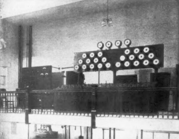
| Interior of Terminal Receiving Station. |
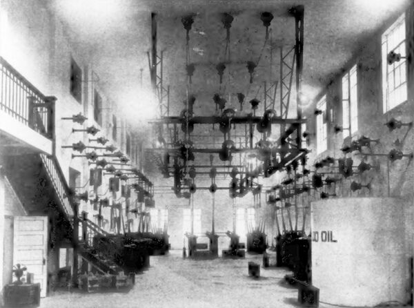
Elaborate provisions have been made for the purification of the transformer oil. This apparatus consists of a number of tanks, pumps, dehydrator and separator with the necessary piping, etc. Tanks are provided for the storage of both "good" and "bad" oil. When oil is to be treated, it is sent to the "bad" oil tanks from which, by passing through the dehydrator and separator, it is purified and then stored in the "good" oil tanks in the basement or pumped to a large storage tank located above transformer No. 1. When moisture or any impurities such as carbonized oil are present in the oil, it is pumped through the dehydrator which has separate compartments filled with unslaked lime and sand. The moisture present in the oil will be absorbed by the lime and all other impurities will be caught in the sand filter. Any other impurities escaping from the dehydrator will be taken care of by the separator which works on the principle of the well-known cream separator, the impurities being separated from the oil by centrifugal force.
The high-tension switches are located on the second floor immediately above the low-tension switch structure. In each of these rooms are the three 66,000-volt oil circuit-breakers, one con-trolling the line, one the transformer bank, while the third is the bus tie switch. Immediately above are the high-tension disconnecting switches with the high-tension bus bars of five-eighths inch copper tubing supported on insulators suspended from the walls or structural members. The minimum distance between phases for 66,000 volts is four feet, while the distance to ground is two feet three inches.
The control gallery is situated opposite the exciter bay in what is now the end of the building, but which, when the station is completed, will occupy the center of the building. The gallery is so located that an unobstructed view of the generator room may be obtained. Instrument posts carrying the indicating instruments are arranged in a semicircle with the exciter instrument board at the back. On the instrument posts are mounted the control switches with the red and green signal lamps. The posts are of two kinds, one having mounted thereon the control switches and instruments for one bank of generators, the other post having instruments and switches for the control of one line and one bank of transformers. An automatic synchronizing device and synchroscope are placed on the exciter instrument board with the control switches and instruments controlling the two exciters. On one side of this gallery is located the local-service switchboard controlling all the lighting, heating and power circuits in the building. One interesting feature is that the building will be electrically heated, the units being of five-kilowatt capacity at 225 volts. The lighting circuits are arranged so either alternating or direct current may be supplied. Alternating current is supplied from a 300-kilowatt 6,600-125-volt transformer and the direct-current from either the exciter or a storage battery.
This battery may be used either for emergency lighting or for the energizing of the direct-current control circuits. It has a rating of 120 ampere-hours and is controlled from a panel close to the exciter instrument board. The battery is made up of sixty-five cells, in each of which seven lead plates are immersed in the electrolyte.
All control and instrument leads before being distributed to the control and instrument apparatus, are collected and fused at the fuse board. Here are also mounted all the relays. A separate board is also supplied for recording instruments. For each transformer bank there are supplied one graphic voltmeter, one graphic wattmeter, one graphic ammeter and two graphic ammeters for the generators.
For the protection of the generators and transformers a double line of air-cooled choke coils have been installed, one set being located between the line and the line circuit-breaker and the other set are installed at the entrance of the transformers. Relays of the inverse-time-limit and reverse-current types, operative at no voltage, are used for the protection of the generators and the high-tension side of each transformer bank, while the low-tension side of the transformer bank and the high-tension lines are protected by inverse-time-limit relays.
Before leaving the building, each phase passes through a separate compartment in which are installed the electrolytic line arresters with their spark gaps which are set to take care of the ordinary surges on the line. If a direct lightning stroke strikes the line. it is taken care of by two sets of horn-gap arresters installed on the roof. These are used in combination with fuses and carborundum resistances. The lines leave the building through a Locke porcelain outlet bushing protected from the weather by hoods of reinforced concrete suspended from the side of the building, the line leaving through the open space at the bottom of the hood.
TRANSMISSION LINE.
The transmission line is built over a special right of way 100 feet wide and is 77 miles long. It traverses a varied country of rock and muskeg in the eastern section and a prairie and well settled farming country towards Winnipeg. Four three-phase lines on two sets of double-circuit steel towers will I be built for the final installation; the present equipment is made up of one line of double-circuit steel towers on which are mounted two three-phase transmission lines and paralleling this one telephone line on wooden poles. In addition a patrol road twelve feet wide has been built from end to end, a considerable portion of which had to be corduroyed.
| |||
| Winnipeg Receiving Station. |
The telephone line consists of a single copper circuit of No. 12 copper carried on glass insulators attached to a single cross-arm. The wooden poles are spaced forty per mile. The line is ungrounded and is so located that when the second line of transmission towers is constructed, there will be about thirty foot between it and the nearest power wire. Transpositions are made four times per mile. Every mile there is a jack box where the patrolman may get in touch with the stations. A duplicate telephone line has been built from Lac du Bonnet to Point du Bois, on the same right of way as the tramway. From Lac du Bonnet to the city, the Canadian Pacific Railroad has a telegraph line built so there is a duplicate line of communication between the Point and the city.
Telephone booths are built along the line at intervals of five miles. Here is kept a full line of repairs for the transmission and telephone lines. A sleeping cot and a stove are provided in each of these booths, while a standard wall set is furnished with disconnecting switches for connecting to the telephone circuit and for isolating each end of that circuit if necessary. Patrol houses for men and stables for horses are at two intermediate points.
| |||
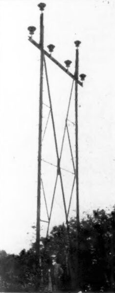
| Standard Braced Tower. |
| |||
| Standard Braced Tower. |
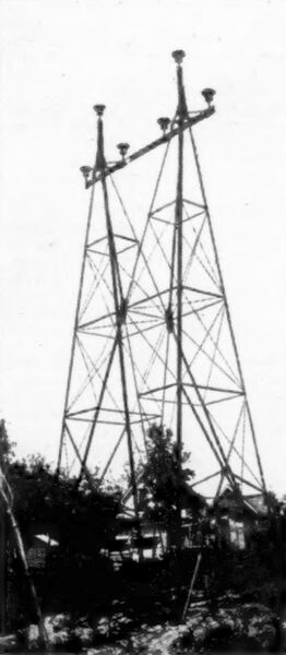
The standard line towers of the type known as "braced" are spaced 1,200 feet apart with an intermediate "flexible" tower half-way between used as a strut. These braced towers carry two three-phase aluminum circuits, the capacity of each circuit being 11,250 kilowatts. The wires of each circuit are spaced six feet apart and located on the points of an equilateral triangle.
The legs of braced towers shown in one of the illustrations are built of 3.5 by 3.5 by 0.25-inch angle iron braced with 2.5 by 2.5 by 0.1875-inch angles. In general the height of these towers is forty-two feet. They were tested at the shops of the manufacturers and successfully withstood 6,200 pounds applied to the end of the cross-arm, representing a load of 1,040 pounds per pin. At right angles to this a load of 1,200 pounds per pin was applied and only a very small deflection observed. The flexible tower is designed to withstand the same stress across the line, but will only stand about eighty pounds per pin in the direction of the line. It is built of six-inch channels for the upright, while the bracing is of the same character as the braced towers. For convenience in transportation the members were not all riveted together in the shop, the field riveting being accomplished by means of a portable gasoline-driven air-compressor set. After assembly the towers were painted with two coats of black paint. The lines crossing rivers and exposed points have as protection a ground wire running from tower to tower about ten feet above the top cables. The pin, of two-inch wrought-iron pipe, is intended to be the weakest member in the tower and is designed to withstand 900 pounds before breaking. On the heavier towers at the river crossings the pin is of solid cross section. The towers at the crossing of the Red River and Winnipeg River are 75 and 90 feet high respectively, with a span of 791 and 939 feet, and are much more strongly built so as to act as dead-ending towers.
All towers are carefully grounded in dry ground by means of copper plates buried in coke and in moist ground by means of copper plates buried close to the footings. The footings of the towers are of concrete blocks eight feet high sunk seven feet in the ground. For muskeg, reinforced hollow blocks grouted in place upon piles were used. If the muskeg was too deep for piles cribbing was used. On rock, the foundation bolts were set in deep and grouted in. As the muskeg country is usually impassable in summer, all materials had to be taken in during the winter on the ice and snow.
The conductors are of aluminum, nineteen strands, of 278,000 circular-mil cross section tested to withstand an elastic limit of 14,000 pounds and an ultimate strength of 24,000 to 29,000 pounds per square inch. The joints of eighteen-inch elliptical tubular sleeves and given three twists per joint have tested out to be as strong as the line itself. In stringing the conductors wooden rollers were fastened over the cross-arms of the towers and on these the cable was paid out, three conductors at a time.
The insulators are of the Locke No. 364 type, having four shells cemented together and on the inside a thimble of malleable iron into which is screwed the insulator pin. The diameter of the top shell is sixteen inches and the insulator is 13.5 inches high. The insulator withstood factory tests 195,000 to 203,000 volts dry and 130,000 to 140,000 volts under a precipitation of one inch of water in four minutes.
The cable is tied to the insulators by means of approximately forty turns of No. 2 B. & S. soft-drawn aluminum wire on each side of the insulator. The wrapping is extended to this distance because if the arc jumps to ground over the insulator, it is better to destroy the wrapping than the cable itself. The line is divided into approximately three equal sections by two disconnecting switch towers. These towers are double structures made up of two standard-angle towers with connecting members with an insulated operating platform. The line is here dead-ended both ways and in the gap is placed a mechanically operated disconnecting switch so connected that the three phases are opened at the same time. The switches move in a horizontal plane through links connected to a lever arm, operated from below by a chain. Interconnections are also placed so that one line may be switched onto the other line in case of trouble, a means thereby being provided where one damaged section may be cut out without sacrificing continuity of service.
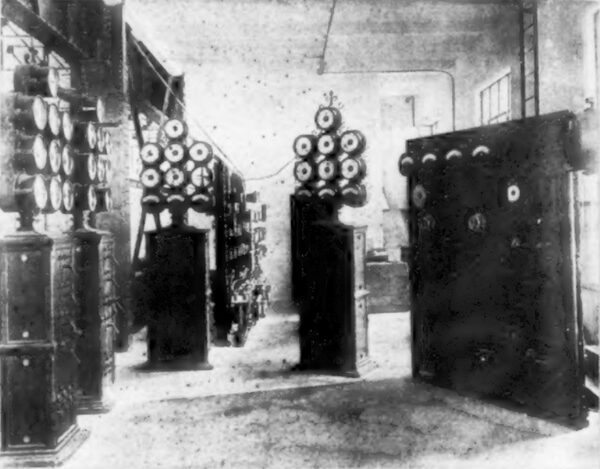
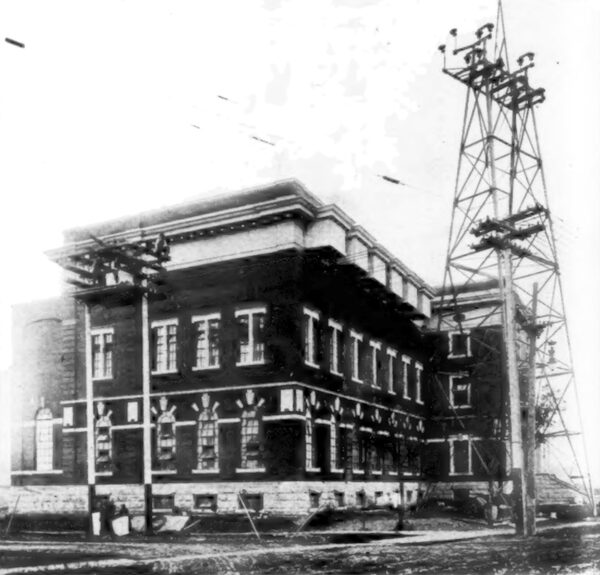
TERMINAL STATION.
The terminal receiving station is situated on the banks of the Red River, occupying the full block between Rachel and McFarlane Streets. This station receives the current at 60,000 volts and transforms it to 12,000, at which voltage it is distributed to different substations throughout the county by means of lead-covered cable in underground conduit. The present station is built to accommodate the equipment for two lines and three banks of transformers. Office space for the accommodation of the construction department has also been provided for. At present the equipment consists of six transformers, each of 2,700-kilovolt-amperes capacity with the necessary protective, switching and control apparatus.
The building is of pleasing appearance of red brick with white stone trimmings. It rests on concrete foundations built on piling. A spur track is laid into the building for the unloading of material. An electric travelling crane of twenty-five tons capacity facilitates the handling of material.
The lines enter the building from a dead-ending tower immediately in front of the station and pass from below into a reinforced-concrete hood and enter the building through a Locke outlet bushing into the discharger compartments where the electrolytic arresters are installed. Each arrester is in a separate fireproof compartment. The lines from here enter the high-tension switch room. Here are placed the high-tension circuit-breakers controlling the lines and transformers with one bus tie connecting the two lines. These breakers have each leg inclosed in an insulated tank of heavy steel. The breaking capacity of each breaker at 72,000 volts is 80,000 kilowatts. The leads are brought out through heavy bushings of the condenser type. There are two breaks under oil giving a breaking distance per pole of thirty-three inches. The contacts are self-aligning, each pair of two contacts having a heavy ring below the lower contact which is compressed when the circuit-breaker is closed.
All high-tension wiring is exposed. It is held in place by insulators suspended from the walls or ceiling and in the center of the room by means of a light steel framework suspended from the steelwork in the roof. The transformer circuit-breakers are all provided with relays so in case of a short-circuit between the generating station and the terminal station on the line, the relay at the generating station will operate, as will the reverse-current relay on this line at the terminal station, due to power feeding back from the terminal-station busbars. In case the short-circuit is heavy and close to the terminal station, the relays on the other line will tend to open. To prevent this possibility, auxiliary relays and their mechanically operated switches are used in conjunction with each reverse-current relay, which under the above conditions, prevents the tripping of any line breaker except that on the defective line.
Close to the office section and located so the operator may have a comprehensive view of the high-tension room, is the control gallery where the bench board and indicating-instrument board are located. The bench board is of enamelled slate, on which are mounted the control switches and dummy busbars of polished copper, indicating connections through the station. The ammeter, voltmeter and frequency-meter receptacles are mounted on the top panels of the desk while the testing receptacles are mounted on the front vertical panels. The instrument board is of steel framework supported on ornamental cast-iron columns, and immediately back of the bench board. Under the control gallery are located the fuse and relay board and the recording-instrument board. On the latter are located the following recording instruments for each line: One alternating-current voltmeter; one power-factor meter; one polyphase wattmeter; one integrating wattmeter, and one integrating wattmeter for each feeder.
An equipment for the testing of the insulation of materials is also installed in this room. It is of 200-kilovolt-amperes capacity and is made up of a testing transformer 2,200 to 180,000 volts; a regulating transformer 250 volts to 2,200 volts; a regulating switch of the drum type which with the regulating transformer will vary the voltage of the testing transformer from zero to 180,000 volts in 100 steps and a one-panel switchboard on which is mounted a 100-ampere carbon circuit-breaker. The equipment also comprises one 200,000-volt electrostatic voltmeter, one 200,000-volt spark gap and three oil-testing cups.
The leads are passed through the floor through bushings of ample dielectric strength to the transformers immediately below. Each transformer is isolated in a separate fireproof compartment and each is of 2,700-kilovolt-amperes capacity 60,000 to 12,000 volts. Six of these transformers are now installed, but compartments have been provided for nine. These vacant compartments are at present being utilized for a substation, there being three 500-kilovolt-ampere transformers, 12,000 to 2,200 volts, installed therein. These are used for the distribution of light and power in this vicinity.
On the same floor, but isolated from the transformers, are two lines of cell structures containing the 12,000-volt circuit-breakers with disconnecting switches and busbars. The cell structure is built up of reinforced concrete with barriers separating the different phases. Ten feeder circuit-breakers of 200-amperes capacity each have been installed, of which six will be used at once. The feeders leave the building in the basement in lead-covered three-conductor cables on racks suspended from the ceiling. Each feeder before leaving the building is connected to a set of low-equivalent lightning arresters as a protection from line surges. For the protection of apparatus in the station, double sets of choke coils and relays have been provided. The line protection is similar to that in the generating station and consists of electrolytic arresters in the building and spark gaps with resistances mounted on the roof.
The cooling of the transformers is accomplished by the circulation of water as a cooling medium. For this a cooling tower of 200,000-gallons-per-day capacity is provided. The water is pumped to the top of the tower where it is divided into tiny particles and trickles over wooden troughs to a concrete water tank below. A large eight-foot fan in the bottom of the tower forces air from below up through the descending water and cools it as it falls. In winter the water is by-passed into the tank without passing through the tower. By these means it is expected a method is provided of cooling the water under all conditions of weather from the coolest day in winter to the hottest day in summer.
A complete system of apparatus for purifying transformer oil has been installed similar to that in use at the generating station.
The equipment for the system was furnished by the following: Turbines and governors, Jens Orten-Boving Company, London, Eng.; generators, Vickers Sons & Maxim, Ltd., Sheffield; transformers and switching equipment at generating and terminal stations, Canadian Westinghouse Company, Hamilton; general works at Point du Bois, John Gunn & Sons. The design and superintendence of the work from its inception up to November, 1908, was in the hands of C. B. Smith; at that time the work was taken over by the firm of Smith, Kerry & Chace, W. G. Chace being engineer in charge.
