[Trade Journal]
Publication: Electrical World
New York, NY, United States
vol. 58, no. 26, p. 1539-1542, col. 1-2
CALGARY HYDROELECTRIC PLANT.
Development at the Horseshoe Falls, Bow River, 50 Miles West of Calgary, Alberta, of the Calgary Power Company.
Single-Circuit, 50,000-Volt Aluminum Transmission Between the Generating and the Terminal Station Energy Sold to Large Cement Mills and Also to Municipality for Railway and Lighting Purposes.
THE following is a short description of the plant of the Calgary Power Company, which was put into operation during the past summer and which is now supplying energy to the city of Calgary and to two large cement mills, one in Calgary and the other in Exshaw, Alberta, Canada.
GENERATING STATION.
The generating station is located on the Bow River at Horseshoe Falls, about 50 miles west of Calgary, Alberta. A double-circuit, 12,000-volt, three-phase, 60-cycle trans mission line runs from there to Exshaw, about 8 miles west, to a substation located near a large cement mill. Two 55,000-volt, three-phase, 60-cycle, single-circuit pole lines run over different routes to the terminal station at Calgary. The accompanying photographs illustrate the location of the plant and some various phases of the construction work.
| |||
| Fig. 1--General View of the Development of Calgary Power Company. |
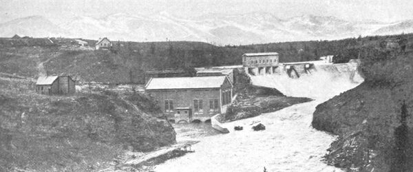
A concrete dam was constructed across the river just above the falls in order to take advantage of the high banks which extend upstream for a few miles from this point. The dam is provided with four hydraulically operated sluice gates, also with stop-log and flash-board spill ways and with an ice run. After passing through the screens the water enters the steep penstocks and is carried to the turbines in the power house and discharged into the river below the lower falls, giving a total head of 73 ft.
The sluice gates are of steel and each is raised or lowered by means of two pistons operated by oil under pressure. Two direct-connected, motor-driven pumps are installed for the operation of these gates, and together with the piping and valves are located in the house built over this portion of the dam. A special grade of non-freezing oil is used. Butterfly valves and stop-logs are provided in the concrete head-block at the entrance to each penstock.
The present installation in the power house consists of two 3750-hp Jens Orten-Boving turbines direct-connected to two horizontal-shaft 2500-kva, three-phase, 60-cycle, 12,000-volt, 300-r.p.m. generators; one 6000-hp Wellman Seaver-Morgan turbine direct-connected to one 4000-kva, three-phase, 60-cycle, 12,000-volt, 225-r.p.m. horizontal shaft generator, and two 330-hp Jens Orten-Boving tur bines direct-connected to two 175-kw, 125-volt, 700-r.p.m. exciters. The transformer equipment consists of two 3000 kva, three-phase, 55,000-12,000-volt oil-insulated, water cooled transformers and three 43.7-kva, single-phase, 12,000-550-volt self-cooled transformers for station service. Provision is made for a fourth generator unit of 4000-kva capacity and two additional 3000-kva transformers and for a 175-kw motor-driven exciter set for future installation. The generators and exciters were furnished and installed by the Canadian General Electric Company. All switching equipment and the transformers were supplied and erected by the Canadian Westinghouse Company.
CONTROL.
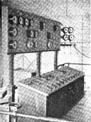
The switching equipment is electrically operated and is controlled from a control desk located on a gallery over-looking the generator-room. The main instrument board is directly in front of the control desk and is supported on columns at a sufficient height to allow the operator a clear view of the generator-room floor. At the rear of the gallery is the recording instrument and relay board, containing all the curve-drawing and integrating instruments and the inverse time-limit, overload relays for all the automatic line and transformer switches. On the main floor and in such a position that it can be seen by the operator on the gallery is the direct-current board controlling the exciters and the generator fields and containing the Tirrill regulators. The generator-field switches are electrically operated from the control desk, while the field ammeters are of the illuminated dial type, so that they may be read from the gallery. At the rear of the direct-current board are the station service-distributing panels, the space between the two boards being closed in with expanded metal screens. Two Tirrill regulators are installed, with provision for a third if necessary, in order to regulate the voltage at Calgary and Exshaw.
| |||
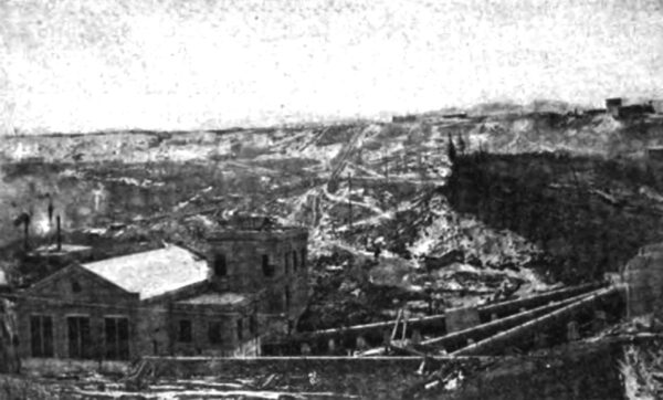
| Fig. 2--Penstocks, Transformer and Switch Rooms and Power House. |
| |||
| Fig. 3--Control Desk and Instrument Board on Gallery of Generating Station. |
The cables from the generators run in conduit to a basement under the center of the generating-room, thence on open shelves along a subway passage to the basement of the switchroom, where the generator instrument trans formers are located in a concrete structure. The oil switches and busbars are located on the floor above in concrete compartments. Two sets of busbars are used, one for the Exshaw and local service, the other for the step-up transformers. The Exshaw bus may be fed direct by either of the 2500-kva generators, or it may be connected to either section of the main bus through an oil switch. This bus feeds the two outgoing 12,000-volt lines and the feeder to the station service transformers. The single main bus is sectionalized into two sections. Each section is fed by a 4000-kva and a 2500-kva generator, and supplies two 3000 kva transformers. The transformers are installed in pockets on the lower floor of the transformer building, two pockets being built on either side of a central passageway.
The transformers are provided with wheels in the base to enable them to be run out on a transfer truck in the passageway and either placed in another pocket or shifted to a position under a chain hoist for dismantling. The upper floor of the transformer building contains all the 55,000-volt busbars and switches and arresters. The busbars are of No. 0000 hard drawn copper supported on porcelain insulators on a pipe framework which also carries the disconnecting switches. The leads from the transformers on the floor below pass up through large floor openings, which are protected with a pipe railing and wire screens 6 ft. high. The 55,000-volt busbars are in two sections, one along each side of the room and tied together through a non-automatic oil switch. The line oil switches are at one end of the busbars, and from these switches the outgoing leads pass upward through disconnecting switches and air-type choke coils through the roof outlet bushings and over the roof to the pole line. Electrolytic lightning arresters are installed on these lines, the horn gaps being mounted on the roof with the tanks in the high-tension room below. On each out going line 55,000-volt series transformers are installed for use with the relays and Tirrill regulators.
| |||
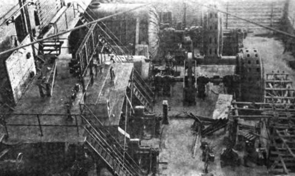
| Fig. 4--Interior View of Horseshoe Falls Station During Construction. |
The low-tension switchroom, besides containing the bus and switch structures, also contains the three 43.7-kva transformers, a room for a storage battery and the electro lytic lightning arresters for the outgoing 12,000-volt lines. The buildings are heated throughout by steam, generated in a boiler in a small annex to the transformer building. Two 5-ft. motor-driven exhaust fans are provided in either end of the generating-room near the roof for summer use.
Oil tanks are provided in a pit below the transformer room, and the piping is arranged so that the oil from any transformers may be quickly drained into one of these tanks and then filtered and pumped back to the transformer. The cooling water for the transformers is taken from the cross-connecting pipe between penstocks No. 2 and No. 3, there being sufficient head to make pumping unnecessary. A motor-driven Rand air compressor is installed in the basement under the generator-room, and air outlets are provided at convenient places about the building for use in cleaning. The generator rheostat resistances are also located in this basement.
TRANSMISSION LINES.
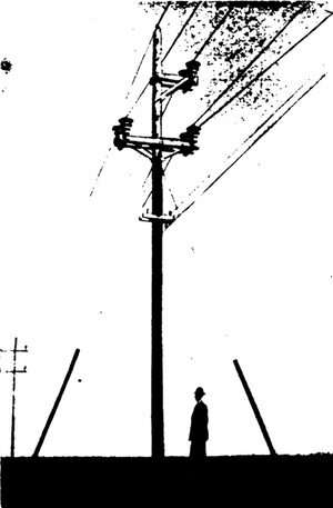
The transmission lines to Exshaw cross the river in a long span at the power house and run along the north side of the river to the town of Exshaw. This line consists of two three-phase circuits of No. 00 aluminum cable on a single pole line. The poles are of cedar, spaced forty to the mile, the standard length being 30 ft. A steel ground wire is carried along the top of the poles on insulators, and a private telephone line is also installed 4 ft. below the lowest cross-arm.
| |||
| Fig. 5--Crossing Near Calgary and Grounding Net Protecting Government Telephone Line. |
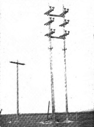
The transmission line to Calgary is a single-circuit ling of No. o aluminum cable supported on wooden cross-arm is on wooden poles spaced thirty-five to the mile. The standard length of pole is 40 ft. and the standard spacing of conductors is 5 ft. 6 in. Locke insulators were used on this line. A steel ground wire is carried on insulators at the tops of the poles and is grounded at every third pole. A private telephone line is also installed 7 ft. below the main conductors. A second line to Calgary is now under construction, running for the greater part of the way over a separate route. For a short distance both lines will be carried on the same poles, one circuit on each side of the pole on three two-pin cross-arms. Every tenth pole of the transmission line is double-armed, head-guyed and side guyed, while special constructions are used at angles and railway crossings.
| |||
| Fig. 6--Structure at Corner on 55,000-Volt Line. |
The terminal station at Calgary is designed to take care of practically the entire output of the above-described power house, and is also arranged for extension if necessary. The equipment as at present installed consists of two 3000-kva, three-phase, 55,000-12,000-volt transformers, one 3000-kva, three-phase, 55,000-2400-volt transformer and two 1250-kva, three-phase, 55,000-2400-600-volt trans formers, with space for one additional 3000-kva unit. The transformers are arranged in a room in separate compartments, with the exception of the 1250-kva transformers, which are both in one pocket. A passageway is provided in front of the transformers with a transfer truck in order to shift the transformers to a position under the chain hoist.
| |||
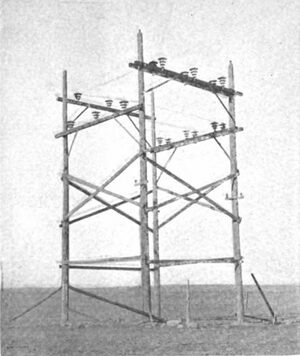
| Fig. 7--Standard Double-Armed Pole, Head and Side Guyed. |
The 55,000-volt lines enter the building through roof in let bushings and are connected through automatic oil circuit-breakers to the 55,000-volt bus which runs along the rear wall, supported on insulators mounted on a pipe framework. This bus is arranged for sectionalizing through an oil switch, one transmission line being connected to each section. The taps to the transformers on the floor immediately below pass down through large floor openings protected with screens. Disconnecting switches are installed in each tap. The electrolytic lightning-arrester horn-gaps are mounted on the roof, and the tanks are placed in two small rooms along the middle wall of the building.
From the transformers the leaded cables pass to the basement under the front part of the building, thence through the floor to the switch and bus structures on the main floor, from them back to the basement ceiling to the inside of the front wall, and thence up the wall to the line outlets near the roof. Provision is made in the basement for the future installation of feeder potential regulators.
There are three sets of bus structures in the low-tension switchroom. The 12,000-volt bus, although installed as a single bus at present, is arranged for a final double bus. The 2400-volt bus is a single bus and is really a short transfer bus. The 600-volt busbars are mounted directly above the transformer oil switches on pipe framework and the leads pass off from them through knife switches to the line outlets directly behind and above them.
The switchboards are located on the upper floor and are arranged in sections. All the switches are electrically operated and are provided with relays for automatic operation, with the exception of the high-tension bus tie switch. The main switchboard is located along the middle partition wall and controls the incoming lines, the bus tie switch and the transformer switches. The 2400-volt feeder board is located along the opposite or front wall, the feeder bus bars being mounted above the switches, which are supported on a framework behind the panels. Provision is made for thirteen feeders. The 12,000-volt feeder switch board is in the same line as the 2400-volt board and controls the outgoing 12,000-volt feeders, provision for five overhead feeders being made. A station service board is installed on the opposite side of the room with a 5-kw motor-generator set and the service transformers. A storage battery is also installed in a compartment on this floor. The 12,000-volt feeders are provided with electrolytic lightning arresters, while the 2400-volt feeders have the spark gap type of arrester.
The basement contains the heating boiler, three oil tanks and the cooling-water pumps, which are motor driven. The piping system is arranged similarly to that in the power house, the cooling water, however, being obtained from a reservoir close at hand.
The complete electrical equipment for the terminal station was furnished and installed by the Canadian Westinghouse Company. The switching is so arranged that the future additional 3000-kva transformer shall have a secondary interchangeable for 2400 volts or 12,000 volts, so that it may be switched in as a spare for either service by simply changing the connection on the terminal board inside the case.
EXSHAW SUBSTATION.
The substation at Exshaw contains four 700-kva, three phase, water-cooled, 12,000-600-volt transformers manufactured by the Allmänna Svenska Electriska Aktiebolaget of Sweden, through its agents, Messrs. Kilmer, Pullen & Burnham, of Toronto, Ontario. The switching equipment consists of a 12,000-volt bus and switch structure controlling the incoming lines and the transformers and a low-tension switchboard with 600-volt bus mounted directly on the panels. A transfer truck is provided for shifting the trans formers, and an oil tank with suitable piping arrangements is also installed. This station is designed to supply one customer only, a large cement mill close at hand. The switching equipment here was furnished and erected by the Canadian General Electric Company.
| |||
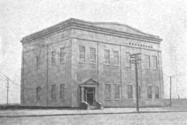
| Fig. 8--Exterior of Calgary Terminal Station. |
The energy delivered in Calgary from the terminal station is used by the city of Calgary at 2400 volts and 12,000 volts and by the Canada Cement Company at 600 volts in its mills adjacent to the terminal station.
This plant went into operation on May 1, 1911, first supplying energy to the Canada Cement Company's mill at Calgary, and shortly afterward to the city of Calgary. The city uses the energy for the municipal street-railway and electric-lighting service. The Exshaw substation was placed in operation some little time afterward. The load at present is in the neighborhood of 5000 kw. The engineering firm of Smith, Kerry & Chace, of Toronto, designed and supervised the construction of the entire development.
