[Trade Journal]
Publication: The Journal of Electricity, Power and Gas
San Francisco, CA, United States
vol. 28, no. 17, p. 371-375, col. 1-2
WESTERN STATES GAS & ELECTRIC CO. AT STOCKTON
BY ROBERT SIBLEY
The City of Stockton, one of the oldest municipalities in the great commonwealth of California, has had an interesting history. The development of the public service corporations, supplying heat and light to its citizens, composes no insignificant part of the life of this city.
Natural gas was discovered in the underlying strata in and about Stockton some forty-five years ago. In 1887 the corporation at that time controlling the supply of natural gas in and around Stockton, also went into the electrical business under the name of the Stockton Gas, Light & Heat Company. This corporation existed until 1904 when the Stockton Gas & Electric Corporation was organized, which absorbed the old holdings of the Stockton Gas, Light & Heat Company and also purchased additional natural gas wells in and about Stockton.
| |||
| Interior of Stockton Steam Plant. |
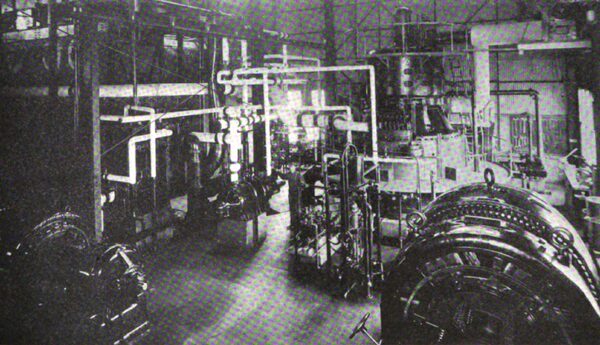
In 1905 the American River Electric Company came into Stockton, having installed an hydroelectric plant on the American River about seven miles to the northeast of Placerville. In addition to this hydroelectric plant, with its 3000 kw. installed output, that company also built a steam plant in Stockton. This steam auxiliary was installed in 1907 and the 1500 kw. vertical turbine at that time installed was the second to be shipped to California.
In 1910 the controlling interest in the American River Electric Company and the Stockton Gas & Electric Corporation was taken over by the H. M. Eyllesby Company of Chicago. This company reorganized the separate holdings under one head and called the combined interests the Western States Gas & Electric Company. The early days of the gas and electric business in Stockton were fraught with many dissensions and much unfavorable public opinion. In the following lines will be found a detailed description of the present holdings of the Western States Gas & Electric Company, which today are held in remarkably high public favor, for deep appreciation is felt over the broad ideals which have been instituted under the new management of the past year and a half.
Gas Plant Data.
Twelve natural gas wells are owned by the company. These wells have an output of 330,000 cu. ft. for every twenty-four hours, and, in addition to this there is manufactured at Station A of the company 300,000 cu. ft. of oil gas.
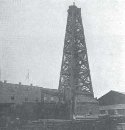
Gas well No. 8 presents an interesting picture. This well was started on November 10, 1904, and at one time was abandoned but today it is being sunk to a depth of over 2800 feet and, from the blue shale indications now being uncovered, the 8% in. casing of this well will soon again be pouring out its blessing of natural flow of gas.
| |||
| Gas Well No. 8. |
The gas plant, which is known as Station A, is being overhauled and within the next month or two will be equipped with modern devices in every particular. The new plant will contain the two old generators, reset with a capacity of 300,000 cu. ft. per twenty hours each, and, in addition, there is being installed a new Jones gas set with a capacity of 750,000 cu. ft. per twenty hours run. A place is being left in this building for another Jones set of larger proportions.
It is interesting to follow in detail the gas manufacture under the improved methods proposed. A total of 90 gallons of oil is used per charge. In the first place 15 gallons are burned in the primary generator to heat the gas set to a sufficient temperature to generate the gas. The air draft is then closed and the additional 75 gallons, known as the make-oil, is sprayed into the heated generator. The heated oil being now in a gaseous state, passes through the generator and superheater as a fixed gas on its way to the wash box. This box is kept under a constant and even water pressure. The water passing through the wash box is kept in a turbulent state so that the lampblack, deposited from the cooling gas as it journeys downward through the water, is carried off with the constantly outgoing water. Hence the washer is a self-cleaning device and is remarkable for its high efficiency. The gas next passes through vertical scrubbers containing wooden trays, placed horizontally one above the other in checkerboard arrangement. Cold water trickles down over this wooden surface and the warm gas journeying upward, coming in contact with these wet surfaces becomes cool and deposits tar and, in addition, the lampblack held in suspension is also carried downward with the trickling water. This water with its lampblack and tar burden is carried on outward to settling tanks in which practically the entire amount of lampblack and tar is recovered and then used as fuel in the plant.
After passing through scrubbers which are 72 ft. x 30 in. in the new installation, the gas passes to the relief holders and is taken through a Root exhauster and thence forced into doubledeck purifiers 18 ft. in diameter and 12 ft. high. These two purifiers each have a capacity of 750,000 cu. ft. and additional space is left for two future purifiers of similar capacity. These purifiers contain iron borings mixed with shavings. As the gas works itself up through this oxide, the sulphur combines with the iron and consequently the gas is left practically free from this injurious content.
| |||
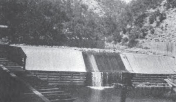
| Dam of South Fork of American River. |
After leaving the purifiers, the gas passes through a 12 ft. station meter which is situated in a steel frame meter house covered with corrugated galvanized iron. Thence the gas journeys into the new gas holder which has a capacity of 750,000 cu. ft. The present holder has but a capacity of 60,000 cu. ft. The natural gas from the twelve wells is stored in a holder, having a capacity of 180,000 cu. ft. Both the natural and oil gas are taken through a Connersville booster, which forces the pressure of the gas supply to proper heights for economic distribution through the city of Stockton.
In manufacturing the oil gas, ten minutes is allowed for heating the charge and ten minutes for the manufacture of the gas, hence three charges are made per hour.
Hydroelectric Plant.
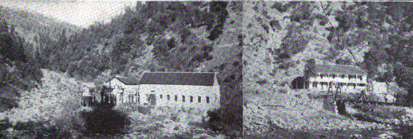
The hydroelectric plant is situated on the south fork of the American River. A concrete dam, 165 ft. along the crest and 40 ft. high diverts the water into a canal. This canal has 4.9 miles of flume, 6 x 5 ft., and 2.1 miles of ditch. From the pen stock, which is 580 ft. above the power house, two combined steel-wood pipes, 30 in. in diameter and 900 ft. long, deliver the water to two hydraulic units which have Doble wheels and Pelton cases. The wheels are of the impulse type. The power house is of concrete construction with steel roof and measures 34 x 80 ft. A Cyclops crane of 20 ton capacity conveniently handles any of the installed apparatus.
| |||
| American River Power House. |
Two 1500 kw. Westinghouse generators furnish three-phase current at 2000 volts, which is stepped up by means of a star and delta connection to 55,000 volts for its transmission into Stockton. Lombard governors perform the function of controlling steady operation.
The transformer room is in a concrete building adjacent to the power house, which measures 24 x 40 ft. In this is to be found three 1500 kw. Westinghouse, oil insulated water-cooled, 2000-55,000 volt transformers. There are also two similar 625 kw. spare transformers.
Two 75 kw. exciter units, installed in the main power house, supply ample excitation for the generators. These exciters are impelled by individual Pelton wheels which are supplied from the main penstock pipes.
| |||
| Map of Western States Gas & Electric Co.'s Transmission Lines. |
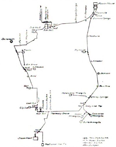
The transmission line is of No. 1 stranded aluminum wire, with the exception of a small portion of the Folsom line between the power house and substation No. 1, which consists of No. 4 copper wire.
The attendants at the hydroelectric plant live at a boarding house owned by the company and managed by the local superintendent of the plant.
Oil circuit breakers are installed on each phase of the transmission line. They are of the Thompson type and are manufactured by the Pacific Electric & Manufacturing Company.
As shown in the illustration there are two high-tension transmission systems emanating from the power house. One branch is known as the Folsom line and the other as the Stockton. Although these two lines are not tied in one with the other, as shown on the map, as a rule, the load on each circuit is well balanced. On the Folsom circuit, 40 per cent of the entire output of the system is used for four large gold dredges owned by the Natomas Consolidated Mining Company, and one by the Ashburton. One-tenth of the output of the system is used to supply the towns of Lodi, Galt, Florin, and other municipalities along the line.
The Stockton line supplies the city of Stockton and operates three gold dredges at Jennie Lind. In addition to this power consumption, two gold mines known as the Alpine Gold Mining Company and the California Exploration Company, are supplied at Plymouth, as well as two gold mines at Placerville. Convenient switches are installed as indicated on the map. In case of an accident these allow of a remarkable pliability and continuity of service to that portion of the line not impaired.
Physical connections are made with the Pacific Gas & Electric Company at two points, one at Substation No. 1 at Natoma and the other at Stockton. Within the next few months physical connection will be made with the Sierra & San Francisco lines which pass within striking distance of Stockton. With such a meshwork as this the Western States Gas & Electric Company is assured of perfect continuity of service.
Wooden poles are used in the transmission system and the insulators are of the four-part Victor type, tested to 100,000 volts. The wires are 6 ft. apart, spaced in an equilateral triangle with the upper apex represented by the insulator on the top of the pole. The complete transmission system comprises about 200 miles of 55,000 volt line.
The plant formerly owned by the old Stockton Gas & Electric Company has been converted into what is now known as Station A. In addition to the principal gas works which are located at this point, there is also installed a 400 kw., 600 volt, 667 ampere, 500 r.p.m., direct current Westinghouse motor generator set. This current is sold to the local electric railway system of Stockton, the Stockton Electric Railway Company. There are also located here two 150 kw. direct current Westinghouse generator sets which are driven by a 200 kw. General Electric synchronous motor. These latter sets are used for elevator service. This station is also used as a distributing substation. In order to handle the voltage properly, three 750 kw. Stanley electric transformers are here installed.
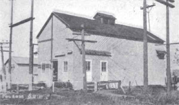
| |||
| Folsom Substation No. 1, Also Showing Pacific Gas & Electric Company's Paralleling Station. |
Station B constitutes the main substation for the long distance transmission line and contains the steam auxiliary. There are installed here three Babcock & Wilcox boilers, which, on the basis of 10 sq. ft. of heating surface per h.p., have each a rating of 402.3 h.p. C. C. Moore oil burners, of the back fire type, efficiently supply heat to the Peabody furnaces. The oil is pumped by means of the 6 x 4 x 6 in. Worthington oil pumps. Oil is stored in a 2500 bbl. steel tank which is situated within a safe distance of the main building and has pipe connections to the main tanks of the Standard and Associated Oil Companies.
The main building, housing the boiler and turbine installation, is 60 x 80 ft. with corrugated iron roofing and concrete foundation. The stack is 105 ft. high, 66 inches in diameter and is of steel. A 2 in. centrifugal. motor-driven pump supplies water for the cooling of the transformers and the make-up water for boilers, pumping from a well 135 ft. deep with a 7 in. bore. Thus the company has its own individual water supply. A connection, however, is made to the city mains, for emergency. A 9000 gallon wooden tank reservoirs sufficient water for ordinary operating conditions.
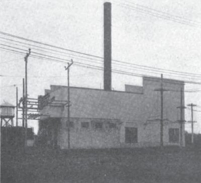
| |||
| Exterior of Stockton Steam Plant. |
The main power generated in this station is supplied from a 1500 kw. vertical Curtis turbine which operates under 175 lb. gauge pressure, 281/2 in. vacuum. A Sturtevant blower. driven by a 15 h.p. motor, supplies forced draft for the generator, and, under these conditions, it is found a 2000 kw. load can be continuously maintained. A 35 kw. Curtis turbine generator set and also a 35 kw. motor driven set constitute the exciters.
The condenser has 6000 sq. ft. of condensing surface. It is of the Worthington type and the same make is also represented in the dry vacuum pump which is 8 x 16 x 12 in. A two-stage Worthington 21/2 in. pump, driven by a 10 h.p., General Electric three-phase motor, acts as a wet vacuum pump in pumping the condensate from the hotwell into the heater. A 14 in. circulating pump is steam driven by an 8 x 12 in. Blake engine.
The step-bearing pressure, which is maintained at 700 lb.. is supplied by either of two 6 x 2V8 x 6 in. Worthington pumps. The usual type of baffler is installed to vary the pressure. Two Worthington feed pumps of the Admiralty type, 9 x 6 x 10 in. are utilized in the feed-water supply. This water is heated by a 1000 h.p. Cochrane feed water heater. A 20-ton traveling crane, manufactured by the Cyclops Iron Works, is installed in the station to lift the heavy apparatus.
The switchboard apparatus is of the General Electric standard construction so far as the alternating current installation is concerned. On the other hand the direct current supply is measured by the Westinghouse switchboard instruments.
This station is used as a distributing point in addition to its function of supplying auxiliary power to the main high tension system. Three 1000 kw. General Electric, oil-insulated, water-cooled transformers maintain the proper 55,000-2200-volt relations. There are also three 275 kw. General Electric, oil-insulated, water-cooled transformers, having the same ratio of transformation. The company supplies considerable power to the Central California Traction Company, which operates an interurban system between the cities of Stockton and Sacramento.
In this station there are to be found a motor generator set, consisting of two 300 kw., 600-volt, 500-ampere direct current Westinghouse generators, directly connected to a 720 h.p., 2300 volt, 60 cycle three-phase Westinghouse synchronous motor. A 60 h.p. induction motor operating at 900 r.p.m., 2300 volts, 60 cycles, is also directly connected to this mechanism and is used as a starting device. This set supplies either 600 or 1200 volts.
Power is also supplied to the Central Traction Company's local lines in Stockton. This is accomplished by means of 400 kw. 600-volt, direct current, Westinghouse generator, directly connected to a 585 h.p. 2200 volt, 500 r.p.m., three-phase, Westinghouse induction motor. Both Station A and Station B may be supplied with energy from the Pacific Gas & Electric Company's lines, the American River station, and soon the Sierra & San Francisco Power Company.
The management have instituted a policy looking toward the improvement of service in every particular. Especially is this true in their efforts to decrease complaints and increase the general usefulness and efficiency of the system. To this end automobiles have been purchased to be ready to answer complaints at all hours of the day and night. A brick garage has been built to house the automobile equipment. This equipment consists of one 2-ton Gramm gas truck. two Reo 1500 lb. gas trucks, one 1-ton electric truck, one 750 lb. electric truck, one 40 h.p. Stoddard-Dayton touring car, and two 20 h.p. Maxwell automobiles.
In its relationship with the mother company, the H. M. Byllesby Company of Chicago, this system presents an interesting illustration of the efficient and close organization maintained. Full and complete managerial reports are sent to the home office each week, including a news letter. This information enables the Chicago office to keep in the closest touch with its subsidiary ownings.
The Western States Gas & Electric Company also controls extensive interests at Richmond and Eureka in California, a complete description of which will appear in later issues of the Journal.
RECENT LEGAL DECISIONS.
When a street car is overloaded and a passenger in attempting to alight gets thrown off the left side of the car and is severely injured the company is responsible for the accident, holds the court in affirming Judge Mitchell Gillian in King county, Wash., who allowed a $6500 verdict in favor of William J. Elliott to stand against the Seattle, Renton & Southern Ry.
When a lineman climbs a pole and falls because of a defective spot in the wood, the company cannot he held responsible, says the Washington Supreme Court in reversing the Spokane Superior Court in the case of Clyde H. Hood against the Pacific Telephone & Telegraph Company, appellant.
