[Trade Journal]
Publication: The Journal of Electricity, Power and Gas
San Francisco, CA, United States
vol. 28, no. 18, p. 393-396, col. 1-2
NOVEL WOODEN TOWER LINE CONSTRUCTION
BY O. G. STEELE
The manner and method of constructing the 60,000 volt wooden tower line of the California-Oregon Power Company involves several unique features which make a description and detailed cost statement of considerable engineering interest.
This transmission line is 24.6 miles in length, connecting the Fall Creek power plant of the California-Oregon Power Company, about 21/2 miles south of the California-Oregon line, with the town of Ashland in Southern Oregon. It ties in with the extensive system which the company has recently acquired by the consolidation of the Siskiyou Electric Light & Power Company, the Rogue River Electric Company and surrounding plants.
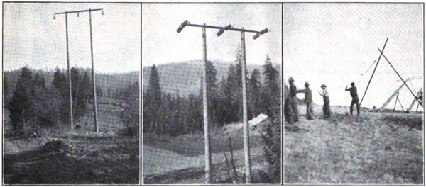
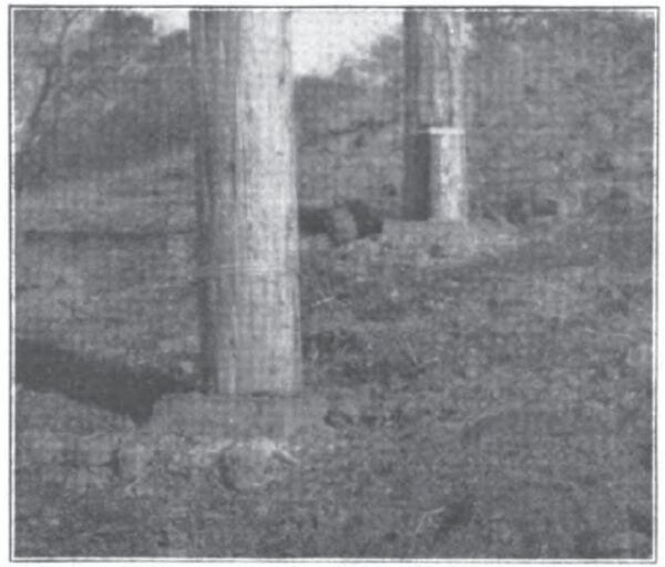
| |||
| Wooden Pole Towers Showing Method of Erection. |
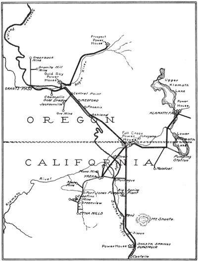
The plants in operation in this system are the Fall Creek plant in Siskiyou County, California, the Gold Ray plant in Jackson County, Oregon, and the Prospect plant at Prospect, Oregon. The former plant situated on Fall Creek, a tributary of the Klamath River and is about one-half a mile from the mouth of that river and within one hundred yards of the Klamath Lake Railroad. The two latter plants are both on the Rogue River. In addition to these three plants there are also two hydroelectric plants at Klamath Falls on the Link River and the Shasta River plant four miles north of Yreka, Cal. Construction work is also being rushed to complete the first two 10,000 kw. units on a new installation on the Klamath River about a mile and a half east of the Fall Creek plant. Since the Fall Creek plant is very nearly the geometric center of the system, as seen from the map, it will handle the dispatching for the entire system.
The Fall Creek plant, constructed during the winter of 1902-1903, being the first generating station of the company, has an interesting history. This plant as completed in 1909 has a capacity of 3200 kw., which energy is generated at 2300 volts, 60 cycles per second, three-phase. It is then transformed to 22,500 volts delta for transmission.
Four lines are run out of Fall Creek to various parts of the country. Line No. 1 takes a southerly course to Etna Mills, a distance of 55 miles, tapping Hornbrook, Yreka, Montague, Ft. Jones and Green-view. Enroute, mines are electrically supplied on the Klamath River, Humbug, Cherry Creek, McAdams Creek, Indian Creek, Patterson Creek, Oro Fino and Quartz Valley.
| |||
| Transmission Lines of California Oregon Power Co. |
Line No. 2 runs due south to Castella, a distance of 75 miles, passing through Dunsmuir, Sisson, Weed, Big Springs and Shasta Valley. Line No. 3, on the other hand, takes a northwesterly course 24.6 miles to Ashland, Ore., where it connects with the Rogue River system. Finally, line No. 4 completes the points of the compass by taking a course due east to Dorris, 23 miles distant, thence north to Klamath Falls, a distance of 20 miles.
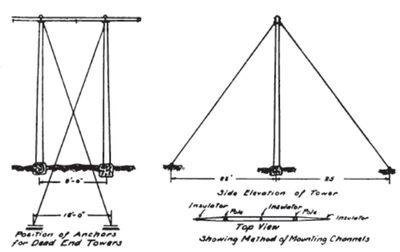
The first two lines mentioned are of the ordinary single pole construction, line No. 1 being constructed for 30,000 volts and line No. 2 for 60,000 volts, single circuit, three-phase. Lines No. 3 and No. 4, however, are of the two-pole type set on concrete bases and anchored at the front and rear as shown in the illustrations. Spans vary from 450 to 1000 feet., one span being 1465 ft. across Jennie Creek Canyon.
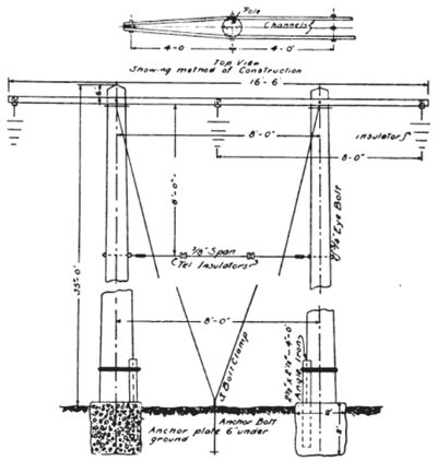
Cast iron anchor plates were used in the foundation work while 3 in. channel iron was employed for the cross-arms. These arms are 16.6 ft, long and are painted with P. & B. paint to prevent rusting. Angle iron 272 x 272 in. was used to bind the poles to the concrete bases shown in the illustration. Insulators of the Locke suspension type are employed. Each insulator, composed of three units, clasps the conductor by means of a straight line clamp. At the point where angles are necessary in the transmission line four units are employed in the insulator.
Every fifth tower is so constructed as to take up the strain at these strain towers, four anchors are employed with guy wires crossed, while for standard towers only two anchor plates are employed.
The raising of the towers proved an interesting problem due to the roughness of the country encountered. While the hillside, composing a portion of the transmission line made only one method applicable, it was not at all times practicable to deliver the tools required. In the illustration one of the best methods of performing this is shown in which a crew of twelve to fifteen men are employed.
| |||
| Details of Tower. |
| |||
| Concrete Bases for Poles. |
The poles are first placed on supports about seven feet above the ground. The guy wires are next passed over the fork as shown and with the aid of a block and tackle the poles are pulled into place, during which process men with pike poles properly guide them. After the poles are thus set on their bases. the guys are pulled through the eye of the anchor rod and simply tightened by hand, another crew following the first one put the guy wires in final taut condition. Later in the progress of the work, it was found that a horse could be used to raise the towers and this method proved satisfactory. As many as twenty-five of these towers may be thus raised in one day. Referring to the guy clamps, the ordinary three-bolt galvanized type was employed but in the future the combination clamp will replace the three bolt design.
| |||
| Details of Tower. |
An average of ten towers per mile were necessary in the construction of the transmission line, although this varied somewhat wherever rolling country prevailed. Thus in crossing canyons, spans were made of full length in most cases. The country through which lines No. 3 and No. 4 pass is rough and in the construction it became necessary to use pack mules in the delivery of cement, water and other material along the line.
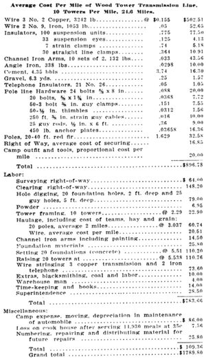
In dead ending the towers the conductors are passed over the straight line clamp direct to the anchor plates in the ground, the suspension type of insulator here used necessitated four units of suspension. The unit cost of construction of such a line has been estimated to be about as follows, assuming 10 towers per mile:
|