[Trade Journal]
Publication: The Journal of Electricity, Power and Gas
San Francisco, CA, United States
vol. 28, no. 19, p. 426-431, col. 1-2
SAN JOAQUIN LIGHT & POWER CORPORATION
Transmission Circuits and Equipment
FOUR classes of transmission and distributing circuits have been well standardized by the company. For the long distance transmission of power between the power stations and the main points of distribution, 60,000 volt transmission has been adopted. For shorter transmissions and distribution to secondary stations 30,000 volts is used. For the distribution of suburban and town orchard pumping and oil well service 10,000 volts is employed. In some of the larger towns and cities, 2400 volts is used for distribution, in most cases being a three-wire delta connection from the transformers, but in one or two cases the 2400 volt has been star-connected to give 4125 volts.
| |||
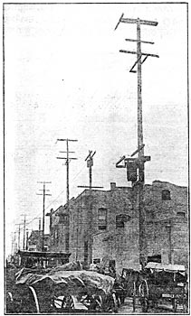
| 30,000 Volt Lines in Foot-Hills. |
Throughout the system all transmission and distribution lines are star-connected from the transformers, the neutrals being grounded.
A spacing distance for poles on all lines of 15 to 16 to the mile has been adopted after a dozen or more years of experience in this section, as being economical and satisfactory under all conditions of operation. There are, of course, some exceptions to this rule in mountainous or rolling country, but by far the largest proportion of lines is in country which is practically level.
 |
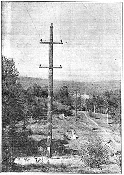
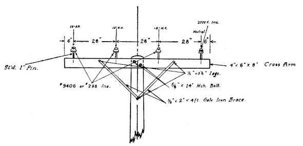
| Elevation of Standard 60,000 Volt Pole. |
The main 60,000 volt transmission lines are mounted on 50 ft. round Washington fir poles. The wires form an equilateral triangle, two of them being at the extremities of the single cross-arm, the third wire being at the top of the pole, mounted on a malleable iron pin. Steel pins are used with lead and porcelain thimbles and standard Locke insulators. The cross-arm is fastened to the pole by the usual gain and a 4 in. galvanized U-bolt` which passes around the pole. In the mountains where trouble has been experienced by eagles in short-circuiting the lines, a novel construction, of mounting two of the insulators directly on the pole, one or either side, is being tried.
Where the circuits cross a railroad track or other wires, whether telegraph, telephone or power, a novel type of grounded cradle is used. This consists of a structural steel frame extending out from the pole a short distance below the lowest wires of the circuit. At the extremity of this cradle is a U-shaped guard to which the ground connection is made. The poles are so placed that should a wire break at any point it will fall on this cradle and be grounded and at the same time fall free from any possible contact with foreign wires.
Guying is resorted to in the ordinary manner, a wooden insulator being slipped over the guy from its point of contact with the ground for a distance up of about 12 ft. In guying fore and aft, a sling is used which is fastened near the extremities of the cross-arm but just inside of the insulator pins. Either end of this sling terminates in a galvanized ring to which the guying cables are fastened.
Both copper and aluminum wire is used on the 60,000 volt transmission lines. From the power station to the Henrietta sub-station No. 0 copper is used. From Henrietta to Bakersfield No. 000 seven-strand aluminum is used, except where entering substations, all entrance wires being of copper.
 |
| 10,000 Volt Pole Line Cut-Out. |
A very successful pole-type cut out for 10,000 volt circuits, mounted whenever a branch is taken from a main line, has been developed and is used exclusively by the company. This consists of a porcelain tube through which passes a fuse wire, mounted on a wooden stick either end of which has a copper blade. The blades engage jaws mounted on insulators, which in turn are held to the arm by a steel bent pin. At the center of the wooden bar on the under side is a threaded socket. In operation the lineman at some distance below all circuits inserts a long stick, the end of which has a male thread and draws the bar and fuse downward to disengage it. This device is simple and positive and costs to manufacture complete, $1.80.
 |
| Safety Grounding Arrangement for Span Wires. |
The construction for the 30,000 volt circuits is in two forms. On some of the main lines feeding at this voltage, comprising the older part of the system, it is quite similar to that just described; except that the triangle is somewhat smaller. The more modern construction, which has been adopted on all of the newer lines and is now standard, is for 40 ft. poles. There is a single cross-arm placed at the top of the pole. This arm carries three insulators; one at each extremity and one in the center. The method of guying and providing for crossing foreign wires is similar to that used on the 60,000 volt lines, but somewhat smaller in general dimensions.
 |
| Detail of Grounding Cables. |
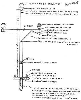
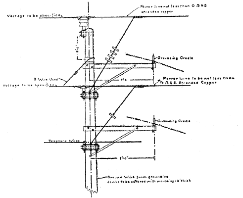
The 10,000 volt distribution circuits are mounted on 35 and 40 ft. round poles, and have a single four-pin cross-arm. Three of the pins carry the three wires of the circuit. The fourth, which is invariably an outside wire, is the ground wire, being the grounded neutral of the system. This arrangement has been found necessary as it is difficult in many places to procure a good ground. It also saves the cost of constructing a ground connection at every transformer set. On both the 30,000 and the 10,000 volt circuits copper is used exclusively.
| |||
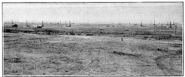
| Transmission Line in Midway Oil Field. |
On the 10,000 volt distribution circuits, where there is no possible chance of extension, four No. 8 hard-drawn copper wires are used. For lateral lines there is a possibility of extension over a comparatively smaller territory three No. 6 and one No. 8 ground wire are used. On main feeders three No. 4 and one No. 6 wires are used, all being of hard-drawn copper.
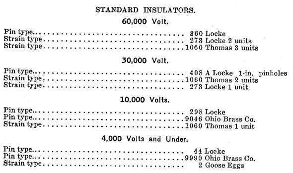
To illustrate the difficulty of procuring ground connections for transformers in the west side oil field district from Maricopa on the south, through the Midway field to McKittrick on the north, a distance of 25 miles, there are but two ground connections, one at Midway and one at McKittrick. The ground connection at Midway is a 2000 ft. well in which a large quantity of charcoal was placed, but in which it is necessary to occasionally pour water to keep the ground in effective condition. Standard insulators adopted for the various types of line are as follows:
 |
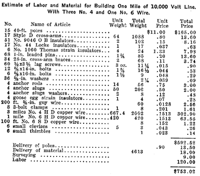
The costs and specifications of the various types of line are carefully kept by the company and tabulated in such a form that it is an easy matter for the company's business agent to figure quickly the proper cost of making an extension to a new customer. The cost of a main section of 10,000 volt distribution is as follows:
 |
Telephone wires are carried on all lines on a two-pin arm under the power wires. The telephone wires are No. 8 hard-drawn copper and on the transmission lines are provided with taps running down the pole so that a patrolman may cut into the line at stated points. The telephone equipment is of a high class, built to order by the Kellogg Switchboard & Supply Company and are standard bridging sets of various resistance from 1600 to 2500 ohms, depending upon the location of the instrument. Insulated stands are provided at every telephone instrument. The telephones are mounted upon iron pipe frames and are in many cases equipped with a marble panel switchboard for operating upon the various lines.
 |
| Detail of Standard 10,000 Volt Pole Line. |
In operating a telephone system in conjunction with high tension transmission, there is always more or less interference from the inductive effect of the high tension current. This is especially true if there is any unbalancing of the high tension circuits or accidental ground on the telephone circuit. This problem of inductive disturbance to telephone lines has been a bug-bear to all transmission companies, but this company has overcome the difficulty to a great extent in a novel manner.
| |||
| Standard Transformer Mounting in Oil Fields Showing Meters. |
At terminal points a standard 3 kw. 2000 volt lightning transformer is introduced between the telephone wires before leaving the last pole. The primary winding of the transformer is bridged across the telephone circuit. The center point of the winding is carried to ground. The secondary winding is left open. This grounding coil serves to remove all static potential from the telephone circuit without in any way interfering with the clearness of speech. Between these transformers and the telephone instrument are inserted fuses placed in porcelain tubes as an added safety. This plan has worked admirably under all conditions for a number of years and seems to have satisfactorily solved the telephone difficulties for this system.
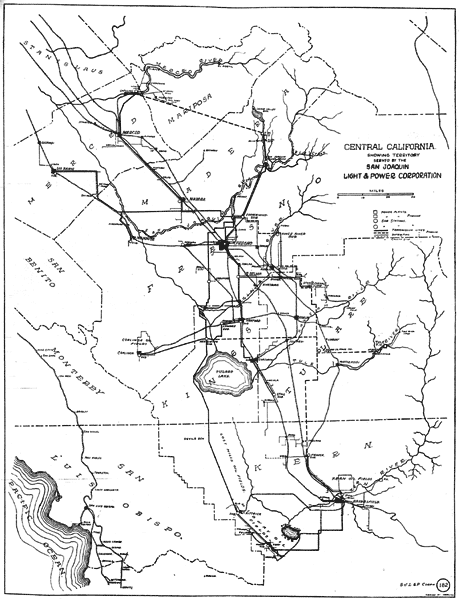 |
| Territory Served by San Joaquin Light and Power Corporation. |
At all of the secondary substations where not over 30,000 volts is received, are placed General Electric, Wirts carbon resistance lightning arresters.
On the 60,000 volt circuits at principal switching points are placed General Electric outdoor type aluminum cell lightning arresters with horn discharge gaps.
A comprehensive system of distribution in the oil well sections is often made possible in the feeding of a group of wells from the fact that oil wells are generally placed with some regularity, about 50 ft. inside of the property lines, these in many cases being on quarter section lines. The accompanying cut shows half of a typical oil well distribution system to 22 or more wells.
| |||
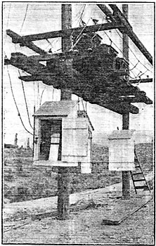
| Transformer Mounting for Commercial Service at Bakersfield. |
In rural districts where the business of the company is both the supply of power for pumping water and for lighting and domestic purposes, if the district is sufficiently populous, a system of distributing lines along the road, which generally follow every section line, is used. It has been found that where service was introduced into a section, even against the prejudice of the inhabitants, it has been eagerly adopted not only for lighting, but for every conceivable domestic service which electric current can be put to; ironing, operating sewing machines, electric fans, washing machines, curling irons and even cooking.
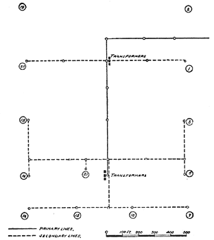 |
| Layout for Lines and Transformers for Group of Oil Wells. |
| |||
| Underground Arc-Circuit Leads From Substation. |
Within the cities the conventional pole distribution is used for both 2400 volt 2 or 3-phase circuits and also series arc circuits. Where possible the lines are carried through alleys between the streets. This is particularly the case in Bakersfield, and here 60 ft. poles are used in the business section of the city. A standard type of transformer mounting is employed. The 2400 volt lines are carried on an arm at the top of the pole. About half way down the pole are the arms carrying the transformers and the fuse blocks are mounted on a separate arm below the transformers. The leads from the lines are brought down to the fuse blocks and then carried back to the transformers. This enables a trouble man to open the fuse blocks and insert new fuses without danger of coming near primary wires.
Series arc systems are invariably used with 6.6 ampere alternating current. There has recently been installed in Bakersfield a new street lighting system, using magnetite luminous arc lamps in series on direct current. The General Electric type M.S. regulator with a mercury arc rectifier, the primary voltage 2200 and rectified voltage 4500 with current of 4 amp., is used at the substation for control of this circuit. Arc circuits are brought out of the substations underground in lead-covered cable and carried to the top of the first pole, standard outlet bushings being used at the top of the pole.
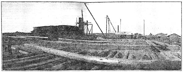
Pole Treating Plant.
During the past years of operation, one of the most serious of the depreciation charges is for the replacement or repair of decaying pole butts. In 1908 a systematic study of this subject was begun with the idea of eventually correcting or preventing the trouble if possible. The poles in use were native redwood, cedar and yellow pine and Washington fir. During this year a line 30 miles long of native yellow pine poles was set after being thoroughly seasoned. Part of the poles were given a brush treatment of carbolineum and with creosote, the remainder received an open tank treatment of creosote, zinc chloride or crude oil. Stubs of untreated timber were set at intervals along the line for the purpose of comparative observation. In June, 1910, after a period of 27 months the line was inspected with the result that the untreated stubs were found to be completely rotted. The brush treated were found to be in a greater or less condition of decay, those treated with crude oil being in somewhat better condition than those given the carbolineum or creosote coat. About one-quarter of the poles given the zinc chloride treatment showed signs of decay while 50 per cent of the entire line which received the open tank creosote treatment were in sound condition.
| |||
| Pole Treating Plant at Fresno. |
| |||
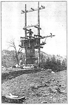
| 10,000 Volt Transformer Mounting. |
On the results of these tests an open tank creoscte treating plant was erected at Fresno in 1911 and all of the poles now used on the system undergo this treatment, but for the butts only.
The plant covers about four acres adjacent to the railroad at the outskirts of the city and comprises a yard for storage of both treated and untreated poles. Poles to be treated are raised with a derrick operated through a double drum hoist by a 15 h.p. Western Electric induction motor. A 50 h.p. tubular boiler furnishes steam for heating the creosote bath. The treating plant consists of two square steel tanks placed at either end of a concrete trough, these are connected by a series of pipes and valves and supplied from large steel storage tanks placed in the rear. The pole which must be dry is lowered into the tank containing hot creosote. This for Washington fir is heated to 212 degrees F. and the pole remains in this bath for four hours. It is then placed in cold oil for an additional period of three hours and the resulting penetration is about three quarters of an inch. With yellow pine the penetration is greater, in some cases extending almost to the center of the pole.
