[Trade Journal]
Publication: Electrical World
New York, NY, United States
vol. 59, no. 22, p. 1161-1182, col. 1-2
DEVELOPMENTS ALONG PUGET SOUND.
Hydroelectric System of the Puget Sound Traction, Light & Power Company
on the Snoqualmie, Puyallup and White Rivers.
Energy Transmitted to Tacoma, Seattle and Everett for Railway, Lighting. and Motor Services
Dominant Features of the Various PlantsOperating Organization and Distribution
System in the City of Seattle Substation Equipment.
SITUATED in the northwest corner of the State of Washington between the Olympic and Cascade Mountains lies what is known as the Puget Sound country, whose distinguishing physical feature is that great inland sea Puget Sound. This body of water has a shore frontage of over 2000 miles, indented by numerous bays and harbors, upon which are located the thriving cities of Bellingham, Everett, Seattle and Tacoma. In the hills rising abruptly from the sea are magnificent forests, the backbone of a vast lumbering industry centered about Everett, a city with 24,814 inhabitants. Immense deposits of bituminous coal are also hard by. The rivers yield abundant fish and the vast salmon canneries of Bellingham with its 24,298 people have made that place known throughout the country. Seattle and Tacoma, with populations of 237,194 and 83,443 respectively, are great manufacturing, shipping and railroad centers, Seattle being the southern terminus of most of the Alaska steamship lines and the twenty-first city in population and importance in the United States.
The region possesses numerous water-powers fed from the everlasting snows of the mountains on all sides and within easy reach of the cities. Nature has done most of the work on the greater part of the sites, especially on the Snoqualmie, Cedar, Nisqually, Puyallup and White Rivers, Where water-power stations have been erected. High heads Prevail throughout the region and the energy is transmitted to Seattle, Tacoma and Everett, and there used for all classes of civic, commercial and industrial work. The developments on the Cedar and Nisqually Rivers are owned by municipalities, the former by Seattle and the latter by Tacoma, although the municipal system at Tacoma is still supplied with energy purchased from the Puget Sound Traction, Light & Power Company and transmitted from Snoqualmie. However, the Nisqually plant now being erected by the city of Tacoma will be placed in operation before the end of the year. The largest water-power plants around Seattle and Tacoma are owned by the Puget Sound Traction, Light & Power Company, and it is to these properties that the present article is devoted.
ORGANIZATION.
The Puget Sound Traction, Light & Power Company is under the management of the Stone & Webster Management Association. The company owns a hydroelectric plant of 36,000 hp (ultimate capacity approximately 108,000 hp) on the White River, 26 miles from Seattle and 15 miles from Tacoma; a hydroelectric system of 25,000-hp rating at Snoqualmie Falls, and steam stations in and about Seattle with an aggregate rating of 25,000 hp. It owns and operates substantially all of the street railway and the largest part of the electric light and power business in Seattle, besides owning and operating the electric light and power business in the larger towns near the cities of Seattle and Tacoma. Its principal officers are as follows: President, Mr. Jacob Furth, Seattle; vice-presidents, Messrs.. F. S. Pratt, Boston, and R. T. Laffin, Seattle; treasurer, Mr. Henry B. Sawyer, Boston, and controller, Mr. A. S. Michener, Seattle. Mr. H. T. Edgar is the Seattle manager of the properties.
 |
| Fig. 1 - Map Showing System of Puget Sound Traction, Light & Power Company. |
 |
| Fig. 2 - Map of the White River Development. |
The Puget Sound Traction, Light & Power Company also owns all or substantially all of the stock of the following companies: Puget Sound Power Company, Pacific Northwest Traction Company, Puget Sound Electric Rail (missing line of text) The Puget Sound Power Company owns and operates a hydroelectric plant rated at 30,000 lip and located at Electron, on the Puyallup River. Energy from this station is transmitted to Seattle and Tacoma.
The Pacific Northwest Traction Company, Mr. D. C. Barnes local manager, owns and operates an interurban electric railway between Seattle and Everett, is constructing an interurban electric railway from Bellingham south through Skagit Valley to Burlington, Mount Vernon and Sedro-Woolley, and owns all of the stock of the Puget Sound International Railway & Power Company, which controls through a ninety-nine year lease the street railway, the water supply and practically all of the electric lighting and power business in the city of Everett, where the office is located.
 |
| Fig. 3 - Transverse Section of White River Station. |
The Puget Sound Electric Railway, Mr. L. H. Bean local manager, owns and operates an interurban electric railway between Seattle and Tacoma and controls the entire railway and a portion of the electric power business in the city of Tacoma through ownership of all the stock of the Tacoma Railway & Power Company and all of the stock (missing line of text) this company is in Tacoma.
The Whatcom County Railway & Light Company, Mr. L. R. Coffin local manager, does the entire electric railway, electric light and power and gas business in the city of Bellingham. The company owns and operates a hydroelectric plant of 2000-hp rating in the mountains at about 5o miles from Bellingham. Its principal office is located in Bellingham.
WHITE RIVER DEVELOPMENT.
The White River development is the latest and largest of the Puget Sound Traction, Light & Power Company's properties and is one of the most interesting on the Pacific Coast. It has only recently been placed in operation and its most notable feature is the immense storage system impounding sufficient water to enable the present installation of 36,000 hp to be operated at full load for an entire month.
| |||
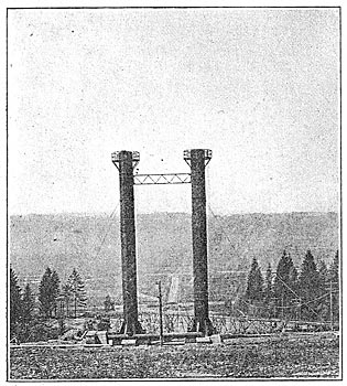
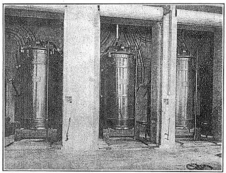
| Fig. 4 - White River Station. Lightning-Arrester Houses in Foreground. |
| |||
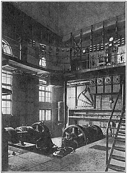
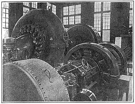
| Fig. 5 - Interior of White River Station. |

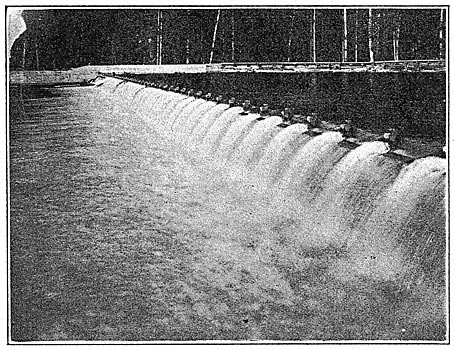
The White River has its rise in the glaciers of Mount Rainier and flows in a general northwesterly direction into Puget Sound. Its minimum flow at the point of diversion is 420 second-ft. A little beyond the town of Buckley dam is thrown across the river, at which point also the headworks are located. The diversion dam is low and broad, with a spillway extending across its entire length. It is 352 ft. long and is built of concrete and rock-filled cribs. Flashboards are provided for raising the level of the river at this point 7 ft. at times of low water; but during flood periods as much as 50,000 second-ft. of water can be discharged over the crest. Concrete wing walls flank the dam on both sides of the river and a concrete intake opening is provided at one side perpendicular to the axis of the dam and parallel to the stream flow. The usual precautions are taken against drift and for shutting off the water from the flume. The gates are arranged to be lifted by means of a gasoline engine or manually. Just beyond the gates there is a sluiceway provided for getting rid of boulders and gravel.
| |||
| Fig. 6 - Dam Across White River at Headworks, Near Buckley. |
| |||
| Fig. 7 - Portal of Tunnel, Showing Gatehouse and Racks Fitted With Motor-Operated Scrapers. |
| |||
| Fig. 8 - Headwork and Flume on White River, Near Buckley. |
| |||
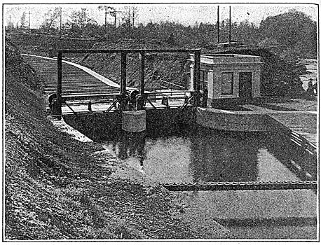
| Fig. 9 - Motor-Operated Gates in House at End of Tunnel, White River Station. |
The intake is connected with a chain of impounding basins by a 28-ft. by 8-ft. wood-lined canal and a timber flume 1.1 miles long, with a slope of 7 ft. in the mile. The flume passes through several cuts where its sills lie on the natural soil of hard clay conglomerate, and for a distance of 2000 ft. it is carried on a heavy pile trestle, filled in but with the weight carried by the trestle. Settling basins, each provided with a culvert and sluicegate to facilitate draining (there being a spillway for the entire basin system to prevent flooding above a predetermined level), are located at five points along the route. The basins are connected by short sections of canal, and after leaving what is known as the Dingle basin the water drops 111 ft. in 2 miles into a natural valley. This section of the canal is timber-lined to prevent erosion, and although a high velocity is encountered in this timber-lined canal at certain points, no wave action or undue disturbance of water is experienced where the grades change. In the last 8500 ft. of the canal there is a drop of 94 ft. to the point where the water enters the natural valley. At this point a secondary plant may be installed at some future time, 3500 hp minimum and 7000 hp maximum being possible of development under an 80-ft. head. It is also possible to employ the chain of lakes or settling basins for storage to give daily peaks of 7000 hp if necessary at this point.
After leaving the last basin the water flows across the valley between two 1600-ft. embankments and then passes through a wide-cut slope of 5 ft. per mile for 2900 ft. into the head of Lake Tapps. Thirteen embankments have been thrown across the ravines which break the shores of the lake, so that the level of the lake might be raised 35 ft.
Approximately 600,000 cu. yd. of earth was required for these embankments, the longest of which is one-half mile and the largest in point of bulk 800 ft. long and 25 ft. high. From the northern end of Lake Tapps runs a long, narrow indentation known as Clode's Arm, at the end of which is the outlet of the reservoir. Heavy cuts had to be made in building the outlet canal, 600,000 cu. yd. being excavated in a length of 2500 ft. The greatest depth is 90 ft. and the bottom width is 45 ft. throughout, except at the western end; where it spreads to a width of 125 ft. for a distance of 300 ft., forming a forebay in front of the portal of the tunnel which carries the water through the western ridge plateau. The maximum capacity of the outlet canal is 3000 second-ft. Penstocks on the western slope carry the water down to the generating station in the valley at Dieinger on the Stuck River, 14 miles from the headworks. The available storage is stated to be 250,000,000,000 cu. ft.
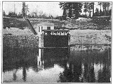
TUNNEL AND PENSTOCKS.
A tunnel 2850 ft. long and 12 ft. in diameter conveys the water from the forebay to the head of the pipe line above the power house. The tunnel, which is lined with reinforced concrete, is equipped with a concrete entrance portal having a bell mouth in order to reduce the friction to a minimum. Air shafts are installed in the gatehouse behind the electrically operated gate leading to the tunnel to avoid vacuum when the gate is closed. Access to the tunnel may also be had through these shafts. It is interesting to note that the racks are equipped with motor-operated cleaning devices in the shape of rakes which are drawn up to the platform by a cable passing around a drum clutched to a motor-driven shaft extending across the rack platform. The racks form a straight panel 50 ft. high and 48 ft. wide. Ice is, of course, unknown in the Puget Sound country and booms keep logs and heavy debris away from the racks, so that the cleaners are merely used for scraping the smaller obstructions from between and in front of the bars.
The tunnel terminates in a circular forebay, 30 ft. in diameter and 75 ft. high, located 250 ft. to the rear of the brow of the hill. Topping the forebay structure at the end of the tunnel is a concrete gatehouse equipped with electrically operated gates controlled from the power-house switchboard. A spillway is provided at the terminus of the tunnel for the purpose of discharging all possible surges in the pipe lines. From the circular forebay to the brow of the hill are smaller concrete tunnels 9 ft. in diameter to which are attached steel penstocks 8 ft. in diameter. An Independent penstock extends from the forebay to the power-house for each unit. At present there are three Pipe lines following the contour of the hill to the powerhouse, two for the main units and one for the exciters. The pipe lines are 2000 ft. long and are laid in trenches and back-filled. The penstocks vary in diameter and thickness from 8 ft. and 3/8 in. at the top to 6.5 ft. and 15/16 in. at the power house.
| |||
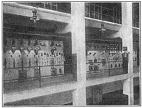
| Fig. 10 - Switchboard Gallery and Exciters, White River Station. |
| |||
| Fig. 11 - Auxiliary Transformer Equipment, White River Station. |
| |||
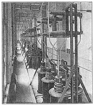
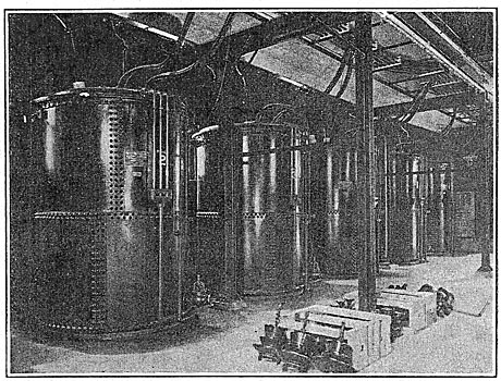
| Fig. 12 - High-Tension Transformers, White River Station. |
| |||
| Fig. 13 - Switchboard Equipment, White River Station. |
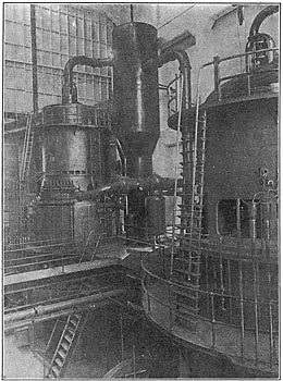
Provision has been made against water hammer in the long columns of water, open standpipes 6 ft. in diameter and 85 ft. high being installed at the upper end of each of the main penstocks, where they pass over the brow of the hill. At the lower end of the penstocks just outside the power house are four air chambers 7 ft. in diameter and 75 ft. high, containing air under a pressure of 190 lb. per square inch, maintained by the static head. Two air chambers are provided for each main penstock, the air cushioning the water column for each unit independently and permitting governing without waste of water. The air chambers are fitted with pivoted ball floats and valves which allow free outward and inward passage of water without leakage of air into the penstocks.
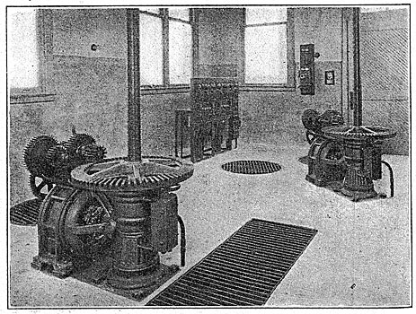
GENERATING STATION EQUIPMENT.
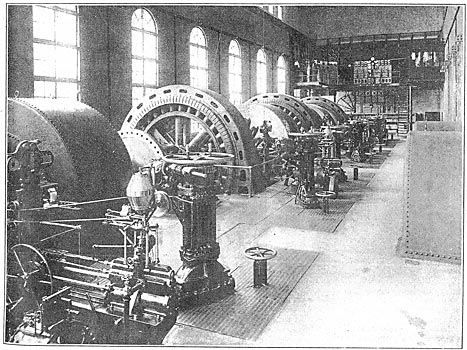
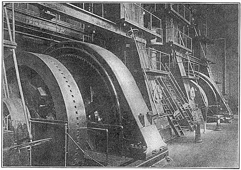
The generating station is 204 ft. long and 82 ft. wide and is built of reinforced concrete. It is divided into a generator room and switch house by partition walls, the switch house being 204 ft. long, 35 ft. wide and three stories high. The generator room is served by a 60-ton, four-motor crane with 5-ton auxiliary hoist and is overlooked by a switchboard gallery. The equipment at present installed comprises two 10,000-kw, 6600-volt, three-phase, 60-cycle General Electric alternators direct-connected to double-discharge, single-runner, Francis-type turbines built by the Allis-Chalmers Company and operating at a speed of 360 r.p.m. under a head of 440 ft. Two exciter units, each rated at 225 kw, 240 volts, and connected to single-nozzle impulse wheels rated at 720 hp and running at 400 r.p.m., are provided. In case it should be found desirable to drive these units by induction motors the base plates can be extended for that purpose.
| |||
| Fig. 14 - Surge and Vent Pipes at Upper End of Penstocks, White River Station. |
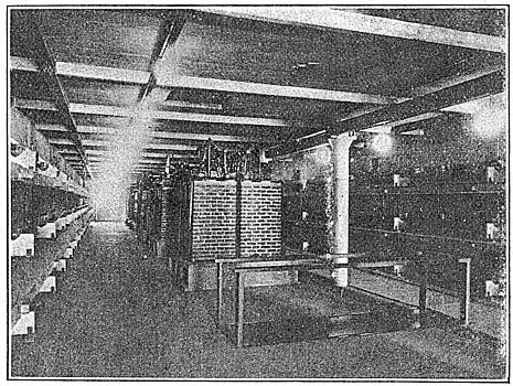
The main transformer equipment now employed comprises two banks of three each, the rating of individual transformers being 3333 kw. These are connected in delta on both the high-tension and the low-tension side and step up the potential from 6600 volts to 55,000 volts. The transformers are of the oil-insulated, water-cooled type, and each bank is housed in a separate compartment shut off from the generator room by means of rolling or sliding doors. The units are arranged in their respective compartments in an arc, so that the tracks for removing them are radial. In addition to the main transformers there arc three banks of transformers for auxiliary service located in a similar compartment near the opposite end of the structure. There are six 75-kw units arranged in two banks of 225 kw, which step down the potential from 6600 volts to 220-110 volts for local lighting service, and one set of three transformers each rated at 200 kw, which step down the potential from 6600 volts to 2300 volts for three-phase motor service.
| |||
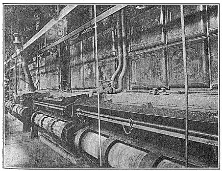
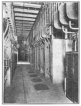
| Fig. 15 - High-Tension Switch and Bus Room, White River Station. |
The main generators, transformers, exciters and low-tension buses are located on the first-floor level. The switchboard and low-tension oil switches are situated in the switch-house section on the second floor, while on the third floor are the high-tension switches and buses. The equipment on this floor is in duplicate, a partition wall separating this floor in two equal sections for its entire length. The high-tension circuits pass out to the roof through vertical roof bushings, the roof structure being equipped with pole-top-type disconnecting switches for each line. These switches are operated from the third floor. The high-tension lines pass thence to towers erected over concrete kiosks housing the lightning-arrester equipment, which is of the aluminum-cell type. There are eight of these houses in all, arranged diagonally up the slope of the hill so that all lines turn at right angles on the towers. This disposition of the lightning arresters was found to be the most advantageous. There are no choke coils in the lightning-arrester circuits since lightning itself is almost unknown. The equipment is chiefly to protect from surges.
| |||
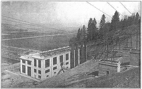
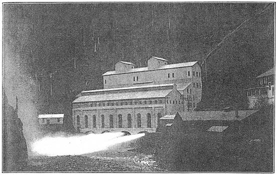
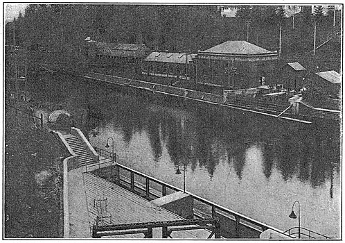
| Fig. 16 - Electron Station on Puyallup River. |
| |||
| Fig. 17 - General View of Electron Station. |
The switchboard equipment is standard throughout, the board itself being split up into three sections. The center section controls the generators, transformers and lines. To. the left is a board controlling the exciter circuits, equipped with a Tirrill regulator, while to the right of the operator's station is a board controlling the local services. There are no automatic devices on the main circuits except on the lines which are equipped with inverse-time-limit overload relays. There are static discharges on the low-tension sides of the main transformers, however. The high-tension buses and connections are made up of iron pipe, the buses being 2 in. in diameter. All of the oil switches, transformers, etc., are piped to the basement, where oil storage and treating equipment of General Electric make are provided.
TRANSMISSION TOWERS.
There are eight three-phase, 55,000-volt lines leaving the station, all of which are made up of No. 4/0 copper. Two of the lines go to Seattle, two to Tacoma, two are incoming circuits from Electron, and two connect with the lines running from Snoqualmie Falls to Tacoma. Thus the output of the Electron and the White River stations is controlled from the latter, while interchange of energy is made possible with the station at Snoqualmie Falls. The tower lines connect with previously existing lines and are of the Archbold-Brady H-frame type, with a circuit arranged on either side of the tower, the lines being 6 ft. apart in a vertical plane, and the lowest line being 42 ft. from the ground. The towers are spaced 400 ft. apart, with a square anchor tower at every fourth span. There are 127 towers in all and Locke pin-type porcelain insulators designed by the Stone & Webster Engineering Corporation are used. The insulator specifications call for a dry test of 120,000 volts.
The station as a whole is remarkably efficient. The generators have an efficiency under full load and including all losses of 96.8 per cent; the waterwheels on a weir test show an efficiency of over 90 per cent, and the transformers are guaranteed to have an efficiency at full load of 98.9 per cent, giving an over-all efficiency of approximately 86 per cent. It should be pointed out that the flumes, head-works, canals and storage basins are installed for a maximum output of 108,000 hp, the tunnel and penstock heads for 54,000 hp, and the present station is capable of accommodating four 18,000-hp units, two of which are now in operation.
DEVELOPMENT ON THE PUYALLUP RIVER AT ELECTRON.
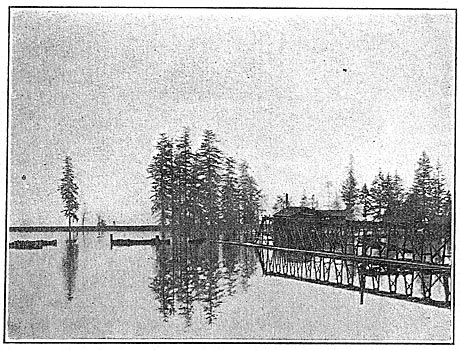
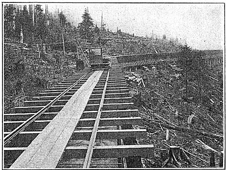
The Electron station of the Puget Sound Traction, Light & Power Company was completed in 1904 and at this writing remains as it was when originally started. For a more detailed description of the development the reader is referred to the Electrical World, Oct. 1 and 8, 1904. Like the White River, the Puyallup River has its source in the glaciers of Mount Rainier, the highest mountain in the United States. The water from the river is diverted just below its junction with the Mowich and carried by means of a wooden flume a distance of 10 miles to a reservoir located on a plateau overlooking the power-house 950 ft. below. Electron is reached over the Tacoma Eastern Railroad from Tacoma, the nearest station being Kapowsin. A spur line runs from the Kapowsin station to Electron, whence a standard-gage cable incline leads to the reservoir site. The headworks can be reached by a wagon road, but more easily by a gasoline engine-driven inspection car traveling on the flume.
| |||
| Fig. 18 - Reservoir at End of Flume Above Station at Electron. |
| |||
| Fig. 19 - Flume and Inspection Car, Electron Station. |
| |||
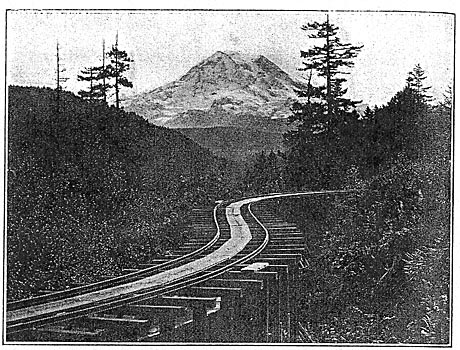
| Fig. 20 - Flume of Electron Station. Mount Rainier in Distance. |
HEADWORKS, FLUME AND RESERVOIR.
Ten miles from the nearest glacier and a half mile below the confluence of the Puyallup and Mowich Rivers is a low diverting dam, 200 ft. long and 5 ft. high, which diverts the water through a masonry intake to a flume skirting the southwest side of the river. The intake is set at right angles to the dam, is 62 ft. wide at the river bank, and is equipped with screens and stop logs in the usual manner. At the junction of the intake and the flume is a radial gate by means of which the flow of water to the flume is controlled.
| |||
| Fig. 21 - High-Tension Room, Electron Station. |
The 10-mile flume has a cross-section of 8 ft. by 8 ft. and is supported on trestle-work. A uniform grade of 7.5 ft. to the mile is maintained, and at various points sand boxes and automatic spillways are provided, together with emergency gates. A light track of standard gage is laid along the top of the flume to facilitate inspection and repairs. While it is possible to float timber in the flume in case of a break, the timber dropping out at the break, the usual method is to take the lumber, etc., to the spot on cars over the tracks on the flume.
The flume empties itself into a reservoir and settling basin, at one end of which is a concrete forebay. A certain amount of storage is possible here to tide the station over interruptions of water supply or to serve in times of peak loads. The forebay is divided into separate gate chambers, each of which is fitted with motor-operated gates controlled from the power-house and the usual screens and stop-log grooves.
PENSTOCKS.
Five penstocks, one for each of the four main units and the other for the exciter units, are carried through the reservoir embankment from the forebay in the form of wood-stave pipes covered with concrete, joining the steel pipes just outside the embankment, where surge pipes are also provided. The larger penstocks are built of steel 1/4 in. thick at the top and 3/4 in. thick at the lower end, the diameter of the pipes tapering from 4 ft. at the top to 3 ft. at the bottom. They are about 1700 ft. long and follow the incline of the plateau to the river below.
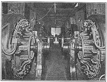
GENERATING STATION AND EQUIPMENT.
The power-house building is of concrete, brick and steel, divided longitudinally into a generator room and a transformer and switch house. The equipment at present installed comprises four 3500-kw, 2300-volt, 60-cycle, 225-r.p.m., three-phase General Electric alternators, direct-connected to as many Pelton waterwheels operating under a head of 872 ft. There are in addition two 150-kw, 125-volt, 600 r.p.m. exciter sets. At the time of their installation the waterwheels were the largest of their kind. The equipment is arranged for complete pilot control of the waterwheel apparatus as well as for electric control from the switchboard. The wheels are of the two-bearing, double-wheel, overhung type, owing to space limitations, one wheel at either end of the shaft. The penstocks enter the building from the rear and pass under the floor to the waterwheels. The supply for each wheel is furnished through a 24-in. cast-steel, specially designed gate valve whose main body is located beneath the floor line. A 5-in. bypass is provided for each gate so that by closing the needle nozzle and opening the bypass the pressure is equalized around the main gate, which can then be easily and quickly opened manually. The main valve can be controlled, however, from the switchboard and opened by an electric motor drive.
| |||
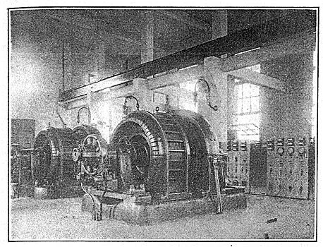
| Fig. 22 - Exciter Units and Switchboard, Electron Station. |
The power developed can be controlled either by deflecting the nozzle or by varying the flow through the nozzle by adjusting the position of the_ needle. The hydraulic governor is arranged for governing the speed automatically by moving the deflecting ends of the nozzles, thus avoiding water hammer. The wheels are 9 ft. 10 in. in diameter and are rated at 7500 hp maximum. The exciter wheels are 38 in. in diameter and are not provided with automatic governors, but are equipped instead with induction motors connected to the same shaft and rated at 200 hp. The induction machines operate as motors or generators, depending on whether they are running below or above synchronous speed. The main units have Lombard governors.
| |||
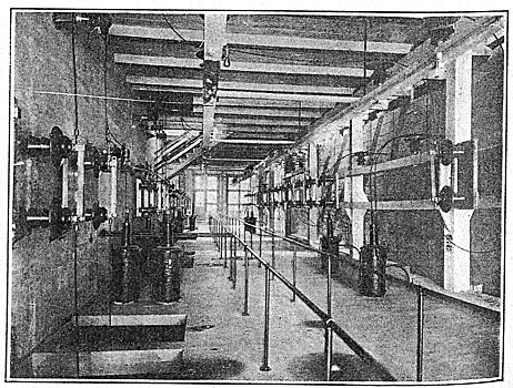
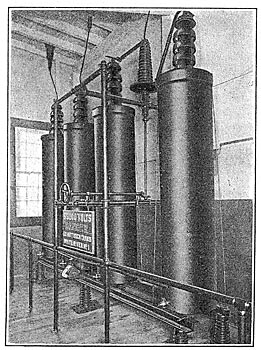
| Fig. 23 - High-Tension Transformers, Electron Station. |
Three banks of three 2333-kw water-cooled, oil-insulated General Electric transformers are installed in isolated compartments shut off from the generator room, by steel curtains. The transformers are connected delta-delta and step up the potential to 55,000 volts for transmission to Seattle and Tacoma. Spring water, supplemented, if necessary, by water from the reservoir, is used for cooling, and the oil chambers are piped to large storage tanks in the basement. The switchboard overlooks the generator room and is located at one end of the station on an elevated platform.
| |||
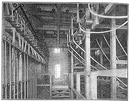
| Fig. 24 - Low-Tension Buses and Switches, Electron Station. |
The general arrangement of the transformer and switch house is as follows: On the floor with the main generators are the high-tension transformers. On the floor above are the low-tension disconnecting switches. The busbar compartments and low-tension oil switches are on the third floor, the buses being of copper bar supported on marble slabs set on edge and resting in turn on concrete slabs forming barriers between the buses. The high-tension disconnecting switches are on the fourth floor, while the oil switches are on the floor above. Above the fifth floor are the high-tension towers for the outgoing lines.
There are two sets of 2300-volt buses, and any generator or transformer can be connected to either one. Between each generator and each set of low-tension buses is a motor-operated oil switch with disconnecting switches on either side. Between each set of buses and each transformer bank there is also a motor-operated oil switch with disconnecting switches on either side, and the same arrangement of oil switches and disconnecting switches is followed out between the transformers and the high-tension buses. The high-tension buses are divided into three sections by switches, each bank of transformers being con- (missing line) the end sections. There are two outgoing lines, each protected by arresters but without choke coils. Static dischargers, consisting of three arresters connected in star with the neutral point grounded, limit the potential of the low-tension winding to 2500 volts above ground.
The control of the entire station is possible from the switchboard. A unit may be started or stopped, a generator brought up to speed and run in parallel with another generator or connected to the buses, a transformer bank connected to either bus, and a transmission line connected in circuit from the switchboard.
TRANSMISSION LINES.
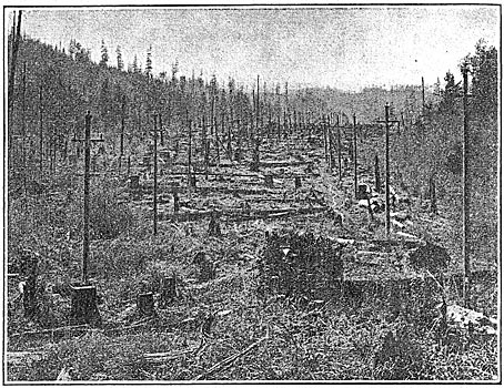
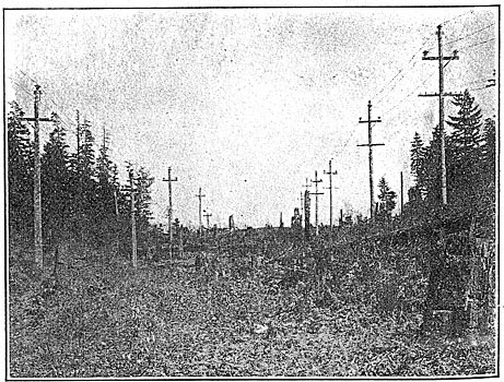
Two transmission lines leave the station and convey electrical energy at a pressure of 55,000 volts to Seattle, 48 miles away, and to Tacoma, 32 miles distant. Wooden poles 45 ft. long and spaced 125 ft. are used. The circuits are of No. 4/0 copper arranged triangularly, each wire being separated 6 ft. from the other. Porcelain insulators of both Locke and Thomas make are used and are fitted with metal pins. The wires are given a third of a turn every 4 miles, and the telephone circuit, which is carried on the same poles 7 ft. posed every tenth pole.
| |||
| Fig. 25 - Transmission Line From Electron Station. |
| |||
| Fig. 26 - 55,000-Volt Line From Electron Station. |
HYDROELECTRIC DEVELOPMENTS AT SNOQUALMIE FALLS.
Of all the hydroelectric developments of the company that at Snoqualmie Falls is without doubt the most picturesque. It is the pioneer of the high-voltage systems of the Pacific Northwest and for originality of design is unique in power-plant annals. The station is hewn into the solid rock, the equipment being in a cavern 3o ft. by 40 ft. by 200 ft., located 270 ft. below the bed of the river. Entrance to the cavern is by means of a vertical shaft to ft. by 27 ft. in cross-section. A tailrace tunnel, 12 ft. by 24 ft. and 480 ft. long, pierces the rock from the cavity containing the generator equipment to the face of the ledge just below the falls. A foot-bridge is suspended in the tailrace by means of which visitors may reach the rocks at the foot of the falls, whence the most inspiring view of the plunging water may be had. Snoqualmie Falls may be reached over the Northern Pacific or by automobile bus from Kirkland connected by ferry with Seattle. The falls are located about 25, miles due east from Seattle, 35 miles northeast from Tacoma and about as far southeast from Everett, to all of which cities the electrical energy is transmitted.
 |
| Fig. 27 - Section Through Generator Room and Switch House, Electron Station. |
 |
| Fig. 28 - Map Showing the Location of the Old and the New Plant at Snoqualmie Falls. |
Since the original development was made in 1900, a 10,000-hp unit has been installed in the cavity, and recently an entirely new station, known as Station No. 2, has been erected a short distance below the falls on a site free from mist. This site, unlike the site of the older station, is capable of enlargement, its cost per kilowatt is less, and from an operating viewpoint it is far preferable. The difficulties of properly lighting and ventilating a rocky cavern 270 ft in the earth will be appreciated by even the novice, not to mention the problem of finding first-class operators who are willing to work in such a location.
The Snoqualmie River rises for the most part in the Snoqualmie National Forest Reserve at the summit of the Cascades, although the river proper is formed 3 miles above the falls by the confluence of three forks, the middle fork being the largest. The headwaters of these forks and some of their tributaries find their source in small lakes at elevations of from 2000 ft. to 4500 ft. The rainfall, which is twice that at Seattle, is heaviest in the winter months, and by September all of the snow on the higher elevations is melted and the river is at its minimum, averaging 55o second-ft. For a distance of several miles above the falls the river flows smoothly with very little grade. At the falls it plunges vertically downward a distance of 270 ft. (almost half as high again as Niagara) and after a few slight rapids continues its peaceful course.
POWER HOUSE NO. 1
The first station at Snoqualmie is located near the brink of the falls, the subterranean chamber mentioned above beginning at a point about 100 ft. upstream and continuing in that direction about 200 ft. directly below the riverbed and at tail-water level. An intake with electrically operated gates is arranged at right angles to the flow of the river and the water drops to the wheels below in two 7.5-ft. steel penstocks which pass down the 10-ft. by 27-ft. shaft. One penstock turns at right angles at the bottom of the shaft and extends horizontally along a bench in the rock and connects with four 2500-hp Doble tangential water" wheels. Each wheel is made up of six 45-in.-diameter runners and two needle regulated nozzles act on each runner. Each unit is direct-connected to a 1500-kw, 2000-volt, three-phase, 60-cycle, 300 r.p.m. Westinghouse revolving-armature alternator.
| |||
| Fig. 29 - Pressure Pipes and Forebay House, Power House No. 2, Snoqualmie Falls. |
The second penstock, which was installed in 1905 (the other having been installed in 1900), connects directly at the bottom with a 10,000-hp radial, inward-flow Francis turbine built by the Platt Iron Works. The unit, which has a horizontal shaft, spiral case, single 66-in. runner and discharges axially into a single draft tube, is direct-connected to a 5000-kw, 2000-volt, three-phase, 60-cycle, 300 r.p.m. Westinghouse revolving-field alternator. The turbine is governed by a Lombard governor acting on its gates, while the tangential wheels are governed by a Lombard governor acting on needle nozzles. The exciter equipment comprises two 125-hp, 300 r.p.m. Felton impulse wheels, direct-connected to 75-kw generators, and one 110-hp, 2000- volt motor-generator set. The tailrace extends the entire length of the cavity under the machinery room floor and empties into the tailrace tunnel. Between the two penstocks is a small passenger elevator driven by a waterwheel with independent supply.
The switchboard is located on a gallery at the elevator through the the shaft to the transformer house on the surface of the ground. There six 2500-kw transformers raise the potential to 60,000 volts for transmission. These transformers are of Westinghouse make. Recently three 2917-kw, 6900-volt to 60,000-volt General Electric transformers were installed in the transformer house for the purpose of stepping up the potential of the energy sent over from Power House No. 2, described later in this article, for transmission.
| |||
| Fig. 30 - Transformer House and Intakes for Power Houses 1 and 2 at Snoqualmie Falls. |
With the installation of the 10,000-hp unit, all the available space in the cavity was taken up, and when later more generating equipment became necessary to take care of the load on the system, then owned and operated by the Seattle-Tacoma Power Company, it was determined to erect a separate station farther down stream, rather than enlarge the subterranean chamber. At first this cavity was ventilated by forcing air down the shaft, a process more or less unsatisfactory; but within recent years this practice has been reversed, and the air is now drawn in through the tailrace tunnel and discharged up the shaft, which acts as a chimney.
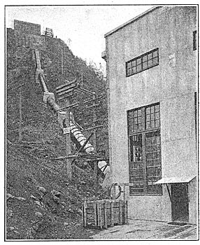
POWER HOUSE NO. 2 AT SNOQUALMIE.
The second station at Snoqualmie, unlike the first station, is built at the water's edge, a tunnel connecting the water above the falls to an open forebay, whence a steel penstock carries it down the side of the cliff to the waterwheel in the station below. The penstock has a length of 496 ft. in a vertical fall of 255 ft. On the west bank of the river directly across from the intake of the older station is the intake for the newer development. A tunnel 1040 ft. long and 12 ft. inside diameter connects the intake with an open forebay 230 ft. long and 20 ft. wide on the brow of the hill overlooking the station. The gatehouse, intake, tunnel and forebay are designed for three 10,000-hp units, one 7-ft. penstock and one unit being at present installed. A spillway 30 ft. wide is excavated from the forebay to the side of the cliff.
 |
| Fig. 31 - Plan and Section Through Power House No. 1 at Snoqualmie Falls. |
The station, which is built of reinforced concrete with one false end wall to allow for extensions, covers an area 45 ft. by 54 ft. It houses one 11,000-hp Francis-type, radial-inflow turbine with double axial discharge, built by the I. P. Morris Company, and a 300-hp Doble impulse wheel, the pipe line for which is tapped from the main penstock just outside the station wall. The main unit is direct-connected to a 8750-kw, 6900-volt, three-phase, 60-cycle, 360 r.p.m. General Electric revolving-field generator. The exciter is rated at 200 kw and besides being connected to the impulse wheel is connected to a 300-hp, 2000-volt, three-phase induction motor. A 50-ton Niles crane spans the room and a gallery at one corner contains the switchboard equipment, below which are the disconnecting switches for the busbars. Below the main floor are the electrically operated oil switches, field rheostats and transformers for the induction-motor circuit. The headgates are electrically operated and are controlled from a special panel in the power house.
Cables carrying the 6900-volt energy pass from the power house up the hill and over to the transformer house on the opposite bank of the river, where the potential is stepped up and the combined output of the two stations transmitted over two pole lines to Seattle, Tacoma and towns en route by three-phase No. 4/0 seven-strand aluminum circuits, and to Everett and towns en route by a single three-phase pole line of No. 4 copper. The lines are connected to the high-tension bus by electrically operated, remote-control, non-automatic oil switches. Aluminum-cell lightning arresters are installed on each line. The Everett line, which is 40 miles long, is spaced on a 7-ft. triangle, while the lines to Seattle and Tacoma are spaced on 9-ft. by 6-ft. flat triangles. Standard 60,000-volt, four-piece, brown porcelain insulators are used with malleable iron pins. The lines to Seattle are 32 miles long and those to Tacoma 35 and 43 miles long.
| |||
| Fig. 32 - Equipment in Power House No. 2 at Snoqualmie Falls. |
| |||
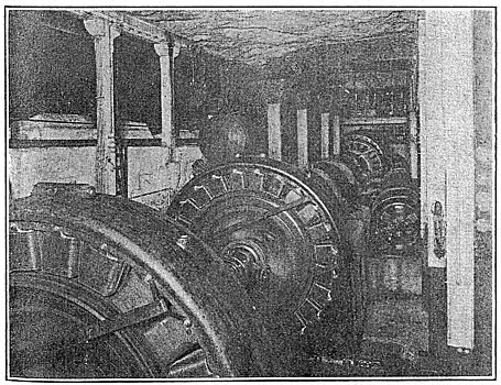
| Fig. 33 - Equipment in Cavity Power House No. 1 at Snoqualmie Falls. |
| |||
| Fig. 34 - Switchboard Gallery, Georgetown Steam-Turbine Station. |
STEAM-TURBINE RELAY STATION AT GEORGETOWN.
Although all of the electrical energy used in Seattle is generated in hydroelectric stations, the company has three steam relay stations in Seattle, the largest and most modern of which is located at Georgetown on the Duwamish River, 6 miles south of the business section of the city. There a reinforced-Concrete station, 80 ft. by 218 ft. and 68 ft. high, has been erected to house 12,000 kw in two turbine-driven units and fourteen 500-hp boilers, together with their auxiliary apparatus, and 1000 kw in motor-generator sets for supplying 600-volt energy for railway service. The station was built in 1908 and has not been used to any great extent.
| |||
| Fig. 35 - High-Tension Transformers, Power House No. 1, Snoqualmie Falls. |
The generating equipment is made up of a 4000-kw and an 8000-kw General Electric turbo-alternator designed to deliver three-phase, 60-cycle energy at a potential of 13,800 volts when operating at a normal speed of 720 r.p.m. The normal steam pressure is 175 lb. with 110 deg. superheat. The boiler-room is equipped with Stirling boilers set in batteries of two with three batteries in a row on the 4000-kw turbine side and four batteries in a row on the 8000-kw turbine side of the longitudinal firing-room floor. The boilers are fired with oil, but provision has been made to permit coal-conveying apparatus to be installed and the storage bunkers for the coal are already part of the boiler-room equipment. A very complete storage and delivery system has been provided for handling the fuel oil supply, which is delivered in tank cars. This system was described in detail in the Electrical World June 20, 1908. Steam to operate each turbine is normally supplied by the row of boilers on the corresponding side of the boiler-room, although both units can obtain steam from either side.
Each of the turbines is connected to a Weiss countercurrent barometric condenser built by the Southwark Foundry & Machine Company. Water for condensing purposes is taken from an intake on the Duwamish River, and the overflow from the hot wells is discharged through an 8-ft. by 12.5-ft. tunnel extending across the land adjacent to the station and emptying in the Duwamish River about 200 ft. downstream from the intake. Excitation energy is supplied by a 40-kw motor-generator set, a 75-kw engine-driven set and a 120-kw motor-generator set. All of the exciters are on the first floor, which is at the same level as the operating floor around the main units.
On this floor are also mounted two 500-kw synchronous motor-generator sets feeding railway load. Two 500-kw transformers supply energy at 2300 volts for lighting circuits and for small motors in the station. The switchboard is located on the third gallery, and on the gallery above are the motor-operated switches on the high-pressure connections of the station. Lightning arresters, static discharges and outgoing transmission-line connections make up the equipment on the top gallery.
| |||
| Fig. 36 - Steam-Turbine Station at Georgetown. |
The main generators and their exciters are controlled from a ten-panel switchboard on the third gallery, while the substation equipment is controlled from a separate eight-panel board on the same floor. A third board, controlling the output of two 500-kw transformers on the first floor feeding two-phase energy for local service, is also located on the third gallery. The 13,800-volt energy delivered by the main units is carried out of the station at that potential to two substations near the business section of the city for local distribution. When the turbines are not running 13,800-volt energy is received from a substation on Massachusetts Street or from a substation on James Street over either one of the two 33,800-volt lines.
GENERATING, STEAM HEATING AND SUBSTATION ON POST STREET.
The Post Street station is located in the heart of the business district and was erected in 1901-1902. The structure is practically four stories high with a basement, the boilers being located on the third floor, with the coal bunkers overhead. The steam piping and ash hoppers are in a room directly beneath the boiler-room, while the generators, substation equipment and switchboard occupy the lower floor, which is about 8 ft. above the street level. In the basement are the condensing apparatus for the engines, a storage battery for the direct-current three-wire system and the necessary wire and cable tunnels.
| |||
| Fig. 37 - Boiler Room in Post Street Station, Seattle. |
A large steam-heating load is supplied from the Post Street station, the exhaust steam from the engines being used for that purpose when the latter are operating. At other times the boilers feed directly into the heating mains through a reducing valve. The steam-heating load extends over a period of nine months, but at no time are there extreme temperatures such as are experienced in the East. However, the load is such that when t h e temperature is lowest the maximum steaming capacity of six boilers is required for the steam-heating system.
The boiler equipment comprises six 500-hp Aultman & Taylor boilers, fitted with chain-grate stokers and burning bituminous coal brought from the company's own mines near Renton, and two 500-hp boilers of the same make equipped for burning oil. The coal bunkers above the boiler-room have capacity for approximately 400 tons and a Hunt conveyor is used to elevate the fuel from the street to the bunkers. The coal is discharged from the cars through an opening in the street, whence it passes through a crusher which discharges it onto the endless chain of buckets. Two crushers are installed, one on either side of the station, the crusher on the east side being used for the coal delivered over the street-car system while the crusher on the west side of the building handles the coal delivered by the railroads.
| |||
| Fig. 38 - Main Units in Post Street Steam Station, Seattle. |
The main steam-generating equipment comprises two 1600-kw revolving-field Westinghouse generators, operating at a speed of 120 r.p.m. and delivering two-phase, 2200-volt, 60-cycle energy. The units, which can carry 2500 kw readily, are directly connected to two twin double-tandem compound McIntosh & Seymour engines rated at 3880 hp at one-half cut-off. The storage battery consists of 154 Electric Storage Battery Company's cells and is floated on the bus of the Edison system at all times, but is never discharged except in emergencies. The normal discharge rate of the battery is 4800 amp. There are three end-cell switches for the positive and three for the negative side of the battery, each having thirty-five points. Each switch is provided with a motor for remote-control operation, and they are so arranged that the motor of either switch can operate all three switches if desired. By means of double-throw knife switches mounted on the switchboard two of the end-cell switches may be used on either the high or the low bus of the Edison system. Each of the direct-current panels of the 250-volt rotary converters is also arranged so that any rotary converter may be used on either the high or the low bus for charging the battery. The Hartford regulators on these rotaries have sufficient range to admit of the charging as described.
The substation equipment consists of five 500-kw, 60-cycle, three-phase Westinghouse rotary converters of 1899, which supply energy to the railway system in the business district; five 500-kw, 250-volt, two-phase rotary converters feeding energy to the direct-current, three-wire system, and the necessary transformers, there being two 300-kw transformers for each rotary.
| |||
| Fig. 39 - Rotary Converts in Post Street Station, Seattle. |
Double buses are provided for the 2200-volt energy and any apparatus may be placed on either bus by means of selector switches. The generators and supply feeders are equipped with 800-amp solenoid-operated remote-control oil switches mounted in concrete cells. The 2200-volt energy for the rotary converters passes through single-phase hand-operated oil switches mounted on marble panels and thence to the transformers. The secondary side of the transformers connects directly to the rotaries without switches. If it becomes necessary to transfer a rotary converter from one bus to another while under load, the oil switch of one phase is opened, the rotary converter continuing to operate as a single-phase machine, and the knife switches are thrown over to the other bus, the other phase being transferred in the same manner. Precaution is always taken to see that both buses are in synchronism before the transfer is made.
STEAM-GENERATING AND HEATING STATION.
A steam relay station previously used in connection with the Snoqualmie system and for steam-heating purposes is located at the corner of Western Avenue and Union Street, Seattle. The 75-ft. by 150-ft. brick structure there erected contains four 300-hp and three 400-hp oil-burning B. & W. boilers, a 1500-hp horizontal cross-compound Allis-Chalmers engine direct-connected to a 1000-kw, 2200-volt, two-phase, 60-cycle generator driven at 120 r.p.m., and a 300-hp De Laval steam turbine running at a speed of 900 r.p.m. and driving two 125-volt Western Electric direct-current machines each rated at 100 kw and feeding energy into the Edison system. In addition there is a 500-kw, 250-volt, direct-current, two-phase Westinghouse rotary converter for the Edison three-wire service, which is supplied with alternating-current energy from two 300-kw transformers. A 35-kw motor-generator set supplies energy for excitation. Most of the electrical load on this station will be transferred to the Union Street substation shortly. The steam-heating system feeds the upper section of the business district and is now operated conjunction with the steam-heating system fed from the Post Street station.
| |||
| Fig. 40 - Union Street Substation, Seattle. |
| |||
| Fig. 41 - Switches and Buses, Union Street Substation, Seattle. |
HIGH-TENSION. TRANSMISSION SYSTEM.
With the consolidation of the various properties on April 15, the general system of distribution has been somewhat modified. The Snoqualmie Falls plant began operations with a transmission voltage of 30,00o at the generating plant and transmitted energy over two aluminum lines to Seattle and Tacoma, both lines being on one pole and going direct from the falls to Renton, where a switching substation is located. Branching at this point, two lines continued south to Tacoma and two north to Seattle, there being only one line of poles for the transmission lines in each case. This company continued to operate in this manner until 1904, when an additional pole line was built from the generating plant to both Seattle and Tacoma and a transmission line placed on each set of poles. The transmission voltage remained at 30,000 volts until 1909, when new transforming apparatus was installed and the line insulators changed, when the transmission pressure was increased to 55,00o volts. The energy is received in Seattle at a step-down substation located at Seventh Avenue and Jefferson Street, about half a mile from the center of the business district, where it is transformed to 2200 volts, two-phase, and 13,800 volts, three-phase, for local transmission.
The transmission pressure from the Electron plant has always been 55,000 volts and energy was originally transmitted over two pole lines to a switching station at Bluffs, where the lines branched, one line going south to Tacoma and the other north to Seattle. Energy from this plant was received in Seattle at a step-down substation located at the corner of Massachusetts and Colorado Streets, where it is transformed to 2200 volts, two-phase, and 13,800 volts, three-phase, for distribution and local transmission.
Since the erection of the White River plant the transmission lines from Electron terminate in the White River station and two lines, consisting of No. 4/0 stranded copper, transmit on wooden poles to Seattle.
The two lines from the Snoqualmie Falls plant which formerly ran directly from Renton to Tacoma also enter the White River plant. There are in addition two transmission lines from White River to Station "A" of the former Seattle-Tacoma Power Company in Tacoma. At the present time the White River station is the main switching point for the 55,000-volt transmission lines.
LOCAL TRANSMISSION AND DISTRIBUTION IN SEATTLE.
The local transmission circuits for the city of Seattle are 2300 volts, two-phase, and 13,800 volts, three-phase. The entire distribution with the exception of the 250-volt Edison three-wire system is at 2200 volts, two-phase. There are eleven substations in Seattle, three of which are combined generating station and substations, while two others are step-down stations transforming from 55,000 volts to the tensions required for local transmission and distribution. One of the latter is located at Seventh Avenue and Jefferson Street, with a transforming equipment for 10,000 kw, and the other is located at Massachusetts and Colorado Streets, with a transforming equipment for 24,000 kw.
About 4000 kw of the power transformed at Seventh Avenue and Jefferson Street is transmitted to the James Street or Post Street substation at 2200 volts, at which point it is either distributed for lighting and two-phase motor circuits or is transformed through rotary converters for the railway and Edison three-wire systems. The rest of the energy transformed at Seventh Avenue and Jefferson Street is distributed to local consumers.
Of the power transformed at the Massachusetts Street substation, about 800 kw is distributed from there for two-phase motor circuits and 175 kw for lighting. Between 4000 kw and 5000 kw is transmitted at 2200 volts, two-phase, to the Post Street substation, the feeders for this transmission being of 500,000-circ. mil copper placed overhead. In the Post Street substation the energy is converted by rotary converters for use on the railway and Edison systems. Radiating from the Massachusetts Street substation are five 13,800-volt, three-phase transmission lines leading to the substations located in the various parts of the city. Two of these linen, consisting of No. 4/0 stranded copper on separate poles, supply energy to the James Street substation, 2 miles distant. One line of stranded aluminum equal to No. 4/0 copper connects with the Georgetown generating station and substation, approximately 3 1/4 miles south. Another stranded aluminum line of No. 4/0 copper equivalent supplies energy to the Union Street, North Seattle and Ballard substations. At a distance of 15,600 ft. from Massachusetts Street, a tap is taken from this line to the North Seattle substation, at which point the size of the wire changes from No. 4/0 to No. 2/0 copper equivalent and continues from there to the Ballard substation, which is 39,600 ft. distant. A No. 2/0, three-phase, 33,000-volt overhead line also connects the Ballard and Fremont substations. From the James Street substation are two No. 1/0, three-phase, 13,800 volt lines on the same poles, supplying the North Seattle and Fremont substations. The tap from these lines for the North Seattle substation is taken at Broadway and Republican Street, which is approximately selector switches are mounted in a box on a pole, so that the North Seattle branch may be switched to either line.
| |||
| Fig. 42 - Transformer and Switching Station at Renton. |
| |||
| Fig. 43 - Tacoma Substation. |
A single-phase solid copper line supplies power to the West Seattle substation, practically 3 miles distant from the Massachusetts Street substation. Between the Georgetown substation and the James Street substation is a No. 4/0 three-phase, 13,800-volt copper line, which is used when the steam turbines in the Georgetown plant are operated. The length of this line is 6.1 miles. Between the Post Street and James Street substations is a 500,000-circ. mil, two-phase feeder about 900 ft. of which is underground. This feeder is used for an interchange of energy between these stations. Between Post Street and Union Street substations is a No. 4/0 overhead two-phase feeder, which is used for an interchange of energy between the respective stations. This feeder is being placed underground at the present time and its size increased to 500,00o circ. mil. All of the two-phase supply feeders between substations are equipped with two-phase induction regulators, so as to vary the load according to requirements.
| |||
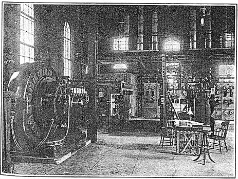
| Fig. 44 - Motor-Generators in James Street Substation, Seattle. |
| |||
| Fig. 45 - Switchboard and Regulators, James Street Substation. |
EQUIPMENT OF SUBSTATIONS.
Alternating current for lighting and two-phase motor circuits is distributed to consumers from all substations except those at Fremont and West Seattle and that on Union Street. The Fremont and West Seattle substations supply energy through motor-generators to the railway system exclusively, while the Union Street substation supplies energy through motor-generators exclusively to the Edison three-wire system. The standard current-carrying capacity of 2200-volt feeders for lighting service is 200 amp and for two-phase motor feeders the power transmitted is 1000 kw.
Connected to the Massachusetts Street substation at the present time are two two-phase motor circuits and one single-phase lighting circuit. The lighting circuit is equipped with a regulator which will shortly be replaced with an automatic induction regulator.
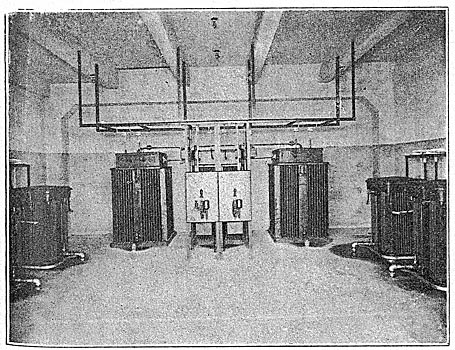
MASSACHUSETTS STREET SUBSTATION
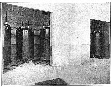
The substation located on Massachusetts Street is the Seattle terminus of the lines coming from the Electron and White River station, by way of the latter, and is on that account the most important substation of the system. The two 55,000-volt lines, made up of No. 4/0 copper on wooden poles with the wires arranged on a 6-ft. triangle, enter the station through the roof, where aluminum-Cell lightning arresters are provided. The transforming equipment provided comprises two 10,000-kw, three-phase, delta-to-delta transformers which step down the potential of the incoming circuit from 50,000 volts to 13,800 volts, and one 4000-kw bank of transformers which steps down the potential from 50,000 volts, three-phase, to 2300 volts, two-phase.
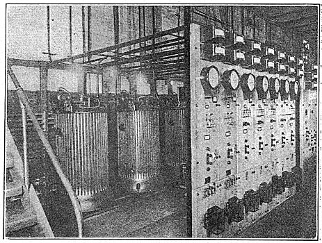
| |||
| Fig. 46 - Switch Room, James Street Substation, Seattle. |
The disconnecting switches and buses for the incoming high-tension lines are arranged on wooden frames, the circuits being protected with 18-32 varnish cambric insulation where there is any probability of operators coming in contact with them. There are two buses provided. Four 50,000-volt oil switches are installed, two of which act as both transformer and line switches, another being employed as a bus junction switch, and the fourth being used on the three-phase to two-phase transformer bank, which is arranged to be switched to either bus by selector switches. All of the 13,000-volt buses and disconnecting switches are mounted in reinforced-concrete cells. There is a double 13,000-volt bus, and each of the five 13,000-volt lines radiating from the station is equipped with an oil switch mounted in a cell.
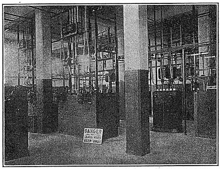
| |||
| Fig. 47 - High-Tension Circuits in Massachusetts Street Substation, Seattle. |
The 2200-volt buses are in the basement, and a remote-control oil switch is connected between the two-phase bank and bus, besides one on each of the two-phase feeders supplying the Post Street substation. The water from the transformers is cooled in a surface condenser, salt water from the bay being pumped through the condenser tubes, on the other side of which is the fresh water from the transformers. There is a 25-ton hoist outside the building under which the transformers can be wheeled in case repairs are necessary.
JEFFERSON STREET SUBSTATION.
The substation located at Seventh and Jefferson Streets is the terminus of the lines from Snoqualmie Falls, besides containing rotary-converters for railway load. Two 50,000-volt lines enter the building and twelve 2200-volt, two-phase distribution circuits leave it, in addition to two 2200-volt, two-phase trunk lines, one of which goes to the James Street substation and the other to both the Post and James Street substations. The equipment installed comprises two 2500-kw, 50,000 to 2300-volt Westinghouse three-phase to two-phase transformer banks; two 2500-kw, 50,000 to 13,800-2300-volt, three-phase to two-phase transformer banks; four 500-kw, 2200 to 12,500-volt, two-phase to three-phase transformer banks; one 500-kw, 600-volt, three-phase rotary; two 500-kw, 600-volt, two-phase rotaries; one 500-kw General Electric two-phase, 2300-volt automatically operated induction regulator, and 2600 kw in transformers for the rotaries.
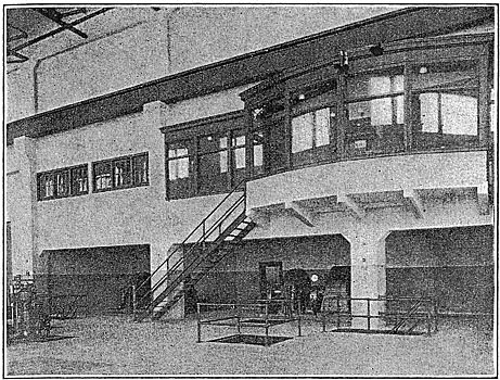
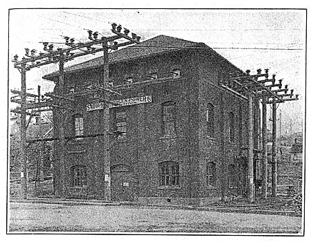
JAMES STREET SUBSTATION.
The James Street substation occupies the north end of a building that was built about the year 1890 as a carhouse and generating station for the Union Trunk Line. The part of the original building occupied by the substation at the present time has been partitioned off from the main part of the building by reinforced-concrete and tiled walls, which renders the space occupied by the electrical equipment practically fireproof.
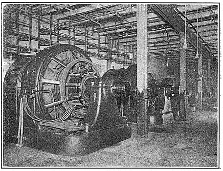
The equipment in this station consists of two 1000-kw, 600-volt generators for railway service, each direct-connected to 13,800-volt synchronous motors, and two 500-kw, 600-volt railway generators connected to 13,800-volt motors. The energy from these machines is distributed to the railway system through nine feeder panels, seven of which are of 1200-amp capacity, the other two being of 2000-amp capacity. There are seven alternating-current lighting feeders for supplying service to the residential district, six of which are equipped with a 200-amp automatic regulator. There is one two-phase motor circuit, and two-phase energy is also supplied from this station at 2200 volts to the Madison Street cable substation for operating the motor that drives the cable. A 13,800-volt, three-phase feeder from this station supplies energy to a motor in the Yesler Way cable substation for driving the Yesler Way cable. The James Street cable line has its cable machinery located in this station and is also driven by a two-phase variable-speed induction motor, which obtains its power from the 2200-volt bus. There are four 1000-kw air-blast transformers stepping down the potential from 13,200 volts to 2200 volts. The energy from these is used as occasion requires for the distribution circuits from this station or transmitted to the Post Street and Seventh Avenue and Jefferson Street substations. Occasionally these substations will supply the James Street substation with energy, and at other times the James Street substation will supply them with 2200-volt energy as conditions require.
| |||
| Fig. 48 - Motor-Generators and Switchboard, North Seattle Substation. |
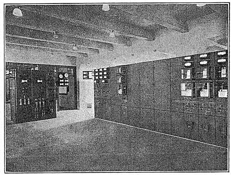
The switch room is located above the generating room and control panels. The two 13,800-volt lines from the Massachusetts Street substation enter this switch room through a wire tower on the northeast corner of the station, pass through General Electric oil switches and connect to double buses by means of selector switches. The two 13,000-volt lines supplying energy to the Fremont and North Seattle substations are taken from the 13,000-volt bus in this substation through an oil switch, whence they may be separated by disconnecting switches. They also leave this station by the same wire tower that the lines from the Massachusetts Street substation enter. The 13,800-volt line from the Georgetown substation is brought in through a large three-conductor, lead-covered cable direct from the fixture pole at the southeast corner of the building. The 13,000-volt feeder supplying energy to the Yesler Way cable substation is taken out through a 13,000-volt three-conductor, lead-covered cable.
With the exception of the Massachusetts Street substation, the James Street substation is the most important as a general distribution center for the 2200-volt and 13,000-volt systems.
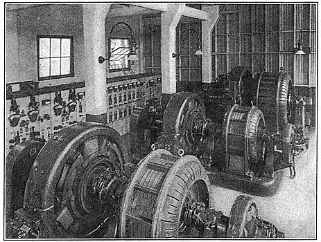
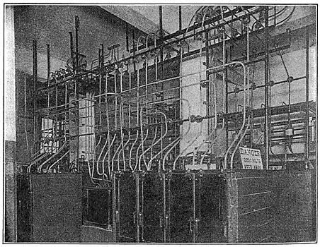
NORTH SEATTLE SUBSTATION.
The North Seattle substation is situated at the corner of Taylor Avenue and Republican Street and consists of a two-story reinforced-concrete building. This building was erected in 1907 and ample space was provided for additional equipment. The machine-room floor of the present building has space for three 1000-kw motor-generator sets and six 1000-kw single-phase air-blast transformers. The present equipment consists of two 1000-kw motor-generator sets for supplying energy to the railway system at 600 volts. The generators are direct-connected to 13,800-volt synchronous motors. There is one bank of air-blast transformers, consisting of two 1000-kw units transforming from 13,200 volts, three-phase, to 2200 volts, two-phase. All switchboard apparatus and control panels are located on the machine-room floor. The oil switches, buses, starting compensators and automatic regulators for lighting feeders are located in the basement. The energy for this station is obtained from two 13,800-volt lines, one of which is controlled from the James Street substation and the other from the Massachusetts Street substation. Double buses are provided for the 13,000-volt system and all apparatus is arranged to be supplied from either bus. The 13,000-volt lines enter the station through a wire tower and all distribution and railway feeder circuits are taken out of the building through the same tower. At the present time there are three 200-amp single-phase lighting circuits equipped with automatic induction regulators and one 1000-kw, two-phase motor circuit. The distribution of. energy to the railway system is controlled through six railway feeder panels, each of 1200-amp capacity, the feeder copper being 1,000,000 circ. mil between the switchboard panel and the outlet of the building, where the circuits are tapped on to 500,000-circ. mil cables run overhead.
UNION STREET SUBSTATION.
The Union Street substation is located at the corner of Union and Post Streets, very close to the heart of the retail business district. It was erected in 1907 to take care of the rapidly increasing load on the Edison three-wire system. Previous to the erection of this station the Edison three-wire system was supplied through rotary converters located in the Post Street station, about 2000 ft. south of the Union Street station. The rotaries receive their alternating-current supply from the Electron water-power plant and two steam-driven generating units, located in the Post Street station. There is also in the Post Street station a storage battery with a discharge capacity of 1300 kw for one hour, which was installed in 1903. The storage-battery and the steam-generating units afforded a most excellent relay and emergency supply in case of trouble with the transmission lines or the water-power plant, which was ample until 1907.
| |||
| Fig. 49 - Lightning Arresters in Massachusetts Street Substation, Seattle. |
In that year it was necessary to install additional equipment, and the property on which the Union Street substation now stands was purchased, the lot being 120 ft. square. Ample ground was obtained to install all the equipment it was thought would ever be necessary at that location. A building 45 ft. wide by 100 ft. long and four stories high was planned, with the idea of installing two storage batteries of the same rating as the one in the Post Street station and 5000 kw in motor-generator sets. Only two-thirds of the building was erected in 1907, and 1000 kw in motor-generator sets was installed, in two 500-kw units. The building is a reinforced-concrete structure, arranged for batteries on the two lower floors, the oil-switch and rheostat room occupying the third floor, while the motor-generators and direct-current switchboards are on the fourth floor.
In 1911 an additional 1000-kw motor-generator unit was installed to take care of the increasing load. Late in the fall of 1911 the consolidation of the Seattle Electric Company with the Seattle-Tacoma Power Company was effected, and question immediately arose as to what disposition should be made of the services in the business district supplied with alternating current by the Seattle-Tacoma Power Company. The question of continuing to supply customers of the latter company with alternating current and placing the wires underground in the business district was considered. This would have made it necessary to maintain two separate underground systems, supplying customers in the same territory, with the rather doubtful condition that the customers supplied from the alternating-current system would have a less reliable source of supply than was afforded with the Edison three-wire system and its storage-battery auxiliary. To have maintained the two separate systems in the same district, both supplied by the same company, the alternating-current system dependent entirely on the transmission lines and water-power plant, while the Edison system was amply taken care of with a storage-battery auxiliary and steam-generating units, would have been rather a doubtful policy. The matter was carefully considered from all viewpoints and it was decided to transfer the customers of the Seattle-Tacoma Power Company to the existing Edison three-wire system. The amount of load to be transferred was approximately 3000 kw, which involved a corresponding increase in the existing Edison three-wire system, both in station equipment and underground feeders and mains. It was decided to complete the building at the Union Street substation in accordance with the plans of 1907 and install two 1500-kw motor-generator sets and a storage battery with an hour rate of discharge of 2600 kw.
The present alternating-current supply for the station is obtained from a No. 4-0, 13,800-volt, three-phase feeder from the Massachusetts Street station and from a No. 4-0, two-phase, 2200-volt feeder from the Post Street station, the 13,800 and 2200-volt feeders being paralleled through a z000-kw transformer bank, T-connected. The increase now being made in the Union Street station has made it necessary to increase the alternating-current supply, and an additional 13,800-volt feeder is being installed. This feeder obtains its energy from the substation at Seventh and Jefferson Streets, which is the main transforming station for Seattle of what was formerly the Seattle-Tacoma Power Company. Thus the two transmission lines from Snoqualmie Falls station to the Seventh and Jefferson Avenue substation and the two transmission lines from the White River station to Massachusetts Street eventually send energy to Union Street. In addition, there is a two-phase, 2200-volt feeder from the Post Street station, where steam-generating units are installed.
| |||
| Fig. 50 - Switch Room, Substation at North Seattle. |
The changes and additions to the Union Street station are being made at a cost of approximately $225,000, all of which is to insure continuity of service in the business district. The motor-generators and direct-current switchboards will be supplied by the Westinghouse Electric & Manufacturing Company and the alternating-current switchboard apparatus by the General Electric Company. The storage battery, which it is said will be the third largest in the country, will be supplied by the Gould Storage Battery Company.
FREMONT SUBSTATION.
The Fremont substation was built in the fall of 1902 to take care of the rapidly increasing railway and lighting load in the north end of the city. The present equipment consists of two 1000-kw motor-generator sets for supplying energy to the railroad system. A good deal of the lighting and motor load was formerly handled from this substation, but the erection of substations in other locations has made it desirable to transfer that business to them.
Three 13,000-volt, three-phase lines supply the necessary energy. Two of these are controlled from the James Street substation by means of one oil switch for the two lines, and the same method of control for these two lines is used in the Fremont substation, selector switches being used to separate the lines when desired. The other 13,000-volt line is controlled from the Ballard substation and in fact forms a tie line between the Fremont and Ballard substations. The line from Ballard terminates on the fixture pole at the station, where it enters a three-conductor, lead-covered cable, which is carried down the pole and underground into the station, where it passes through the necessary disconnecting oil and selector switches, to be used on the double bus.
BALLARD SUBSTATION.
The Ballard substation was built in the fall of 1909 and is a brick building with a row of reinforced-concrete columns about midway its length to support the oil-switch gallery, traveling crane and roof. The oil switches are mounted in concrete cell work, while the buses are open and mounted directly above the oil switches on channel and angle-iron framework. Energy at 13,200 volts, 'three-phase, is obtained over a line from the Massachusetts Street substation and the tie line previously mentioned between the Fremont and Ballard substations. A 13,000-volt line is taken from this substation for supplying the Halls Lake substation, 10.45 miles north of the Ballard station, on the Seattle-Everett Interurban line. All wires are taken into this substation underground. They terminate on the fixture poles, where they enter lead-covered cables and are taken down the poles in iron pipes into the underground ducts.
The equipment of this substation at the present time consists of one 1000-kw and one 500-kw motor-generator set for railway service. There are three single-phase lighting circuits, two of which are equipped with 200-amp automatic induction regulators, the other circuit being equipped with a hand-operated General Electric regulator; one two-phase, 2200-volt motor circuit, and one bank of 2000-kw, 13,000-volt, three-phase, to 2200-volt, two-phase, air-blast transformers. Double buses are provided for the 13,000-volt supply and all apparatus is arranged to be switched to either bus by the means of selector switches. Only a single. bus is provided for the 2200-volt system at this time, but space is left for an additional bus. All apparatus is equipped with oil switches, mounted in concrete cell work.
 |
WEST SEATTLE SUBSTATION.
The West Seattle substation was built in 1907 and is strictly a railway substation. The voltage of the supply which is obtained from the Massachusetts Street substation is 13,200. The equipment at the present time consists of one 500-kw synchronous motor-generator set and two 300-kw motor-generator sets. A 1000-kw bank of transformers consisting of two 500-kw units is used to transform from 13,800 volts to 2200 volts. The wires are brought into this substation overhead through a wire tower. Only one 13,000-volt bus is installed at the present time, but provision has been made for a double bus when it becomes necessary to install it. The 500-kw unit and its starting compensator are equipped with solenoid-operated General Electric remote-control oil switches mounted in concrete cell work. The 300-kw units are controlled by oil switches mounted on the switchboard panels. Each of the 300-kw units has its own starting compensator and is also provided with a direct-current starting box.
GENERAL SYSTEM OF DISTRIBUTION.
Some of the main features of the stations and substations are as follows: Synchronous motor-generator sets are used almost exclusively in converting from alternating current to direct current. Double buses are provided for both 13,800-volt and 2200-volt systems in all stations having more than one line supplying them.
All motor-generators are equipped with direct-current starting boxes and alternating-current compensators. At least two supply lines feed all substations in the city, except the one located at West Seattle. Ordinarily the 13,800-volt lines are not paralleled at any of the substations except for the purpose of transferring load or to meet emergencies when some line or apparatus may be out of commission.
The operation is controlled by a load dispatcher, who is located in an office adjoining that of the superintendent of operation. All orders for cutting in or out lines or apparatus or shifting loads are given by the load dispatcher. The most important substations and generating stations have two telephone lines to the load dispatcher's office.
SUBSTATIONS OUTSIDE OF SEATTLE.
While the foregoing are the principal substations devoted to the light and power business of the Puget Sound Traction, Light & Power Company in 'Seattle, it by no means limits the number of substations supplied from the transmission systems. Limitations of space, however, preclude the possibility of describing these in any detail. Energy from the hydroelectric stations described is transmitted to Tacoma and Everett, in both of which cities substations and steam relay stations are installed. Most of the substations are connected to the Snoqualmie system. The Tacoma substation of the Snoqualmie system has installed two 2500-kw, 50,000-2300-volt (three-phase to two-phase) transformers; two 2500-kw, 50,000-13,800-2300-volt (three-phase to two-phase) transformers ; three 1000-kw, 50,000-27,600-volt (three-phase to three-phase) transformers; one 500-kw, 600-volt rotary with two 300-kw transformers, and a 500-kw Westinghouse two-phase, 2300-volt automatic induction regulator. In the Everett substation there are installed two 1000-kw, 50,000-13,800-2300-volt (three-phase to two-phase) transformers and a fifty-light 6.6-amp constant-current transformer. There are two other substations in Tacoma owned by the Puget Sound Traction, Light & Power Company which have steam-generating apparatus, in addition to a new substation now being built by the city for its municipal system. At present Tacoma purchases its energy from the Puget Sound Traction, Light & Power Company. There are in Everett also a steam station with substation equipment and a substation owned by the Puget Sound Traction, Light & Power Company. These stations were operated independently of the Snoqualmie system before the consolidation. Substations are also located at Sumner and Puyallup.
Other substations are maintained at Renton, 1500 kw; Issaquah, 100 kw; Snohomish, 500 kw; Columbia City (railway), 800 kw in rotaries with transformers; Columbia, 200 kw; Denny Renton Clay Works, near Renton, 1200 kw; North End Water Company, Tacoma, 300 kw; Tacoma Smelting & Refining Company, Point Defiance, 3330 kw; Tacoma pumping station, 1500 kw, and Auburn, 100 kw.
SEATTLE ORGANIZATION.
The consolidation of the various properties necessarily resulted in some changes in the personnel of the local. organization in Seattle. Mr. H. T. Edgar, formerly manager of the Seattle Electric Company, is now the manager of the Seattle division of the Puget Sound Traction, Light & Power Company. The superintendent of light and power is Mr. W. J. Grambs, formerly of the Seattle Electric Company. Mr. G. E. Quinan is operating superintendent, Mr. S. C. Lindsay is electrical engineer, Mr. C. R. Collins is superintendent of distribution, and Mr. W. J. Santmyer is engineer of the steam and steam-heating stations. The. superintendent of water-power is Mr. John Harisberger, formerly general superintendent of the Seattle-Tacoma Power Company. The superintendent of transmission lines. outside of the city is Mr. Magnus T. Crawford, and Mr. R. E. Thatcher is head of the department of services and installations. The sales manager of the company is Mr. Morton Ramsdell, formerly manager of the Seattle-Tacoma Power Company. The latter company, it might be mentioned, was a consolidation of the Tacoma Cataract Company, Snoqualmie Falls Power Company, Seattle Cataract Company and the Mutual Light & Heat Company. It also controlled the Diamond Ice & Storage Company. The former Seattle Electric Company owned the capital stock of the Puget Sound Power Company and of the Seattle-Everett Traction Company. The Puget Sound Power Company owned in turn the station at Electron, on the Puyallup River, while the Seattle-Everett Traction, Company owned the capital stock of the Puget Sound International Railway & Power Company, lessee of the Everett Railway, Light & Water Company. The controlling interest in the Seattle Electric Company and in the Seattle-Tacoma Power Company was owned by the Pacific Coast Power Company, which built the station on the White River. All of these various properties, etc., are now consolidated in the Puget Sound Traction, Light & Power' Company, as mentioned in the beginning of this article.
