[Trade Journal]
Publication: Electrical World
New York, NY, United States
vol. 59, no. 22, p. 1183-1190, col. 1-2
THE MUNICIPAL PLANT AT SEATTLE.
11,000-kw Hydroelectric Development on Cedar River and Auxiliary 1500-kw
Water-Power Station in Seattle.
Energy Transmitted 39 Miles at 60,000 Volts to SeattleDistribution System and Extensive
Ornamental Street-Lighting EquipmentTwo-Phase, Five-Wire System Employed
One Suburb Lighted from Single Wire.
FOR the lighting of the city of Seattle a large system has been built, comprising a hydroelectric generating station on the Cedar River, 39 miles outside the city; two 60,000-volt transmission lines, an auxiliary waterpower station in Seattle using water from the city reservoir, and an extensive city distribution system serving approximately 20,000 customers and supplying energy for street lighting. With the exception of a small amount of direct-current energy in the business district of the city for elevator motors, all the rest of the system is supplied with alternating-current energy.
| |||
| Fig. 1 - Cedar Lake, Used As Reservoir, Seattle Municipal System. |
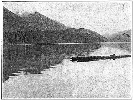
Cedar Lake, which is used as a reservoir, is situated just west of the crest of the Cascade Mountains and about 43 miles southeast of Seattle. The tributary watershed, 79 square miles in area, is extremely rough and mountainous and is covered with a dense growth of fir and hemlock timber. Precipitation over this area is very heavy, amounting to 110 in. a year at the lake level, and probably much more on the surrounding mountains. Careful records of run-off are kept, use being made of the dam spillway as a weir and water elevations being noted daily. The flow averages about 400 cu. ft. per second and is made unusually steady from the fact that the melting snow and ice on the mountain feeds the stream during June, July and August. The present dam, built of timber cribs filled with rock, is located three-fourths of a mile below the natural outlet of the lake and raises its level 18 ft., impounding about 1,000,000,000 cu. ft. of water. The spillway is in the center of the dam, and the control gates for the penstocks are placed in one wing, which also carries intake screens made up of wooden bars.
| |||
| Fig. 2 - New Masonry Dam, Seattle Municipal System. |
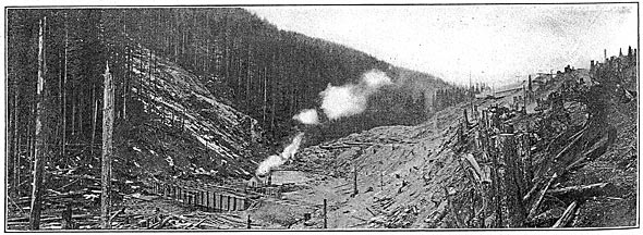
In order to develop the full power of the site, water storage is necessary; and to that end a concrete dam, 215 ft. high and 720 ft. long, is now in process of construction at a point 2 1/4 miles below the lake outlet. This dam when completed will raise the lake level an additional 58 ft., increase its area from 1.91 to 5.23 square miles and render 60,000 hp available at the waterwheels.
| |||
| Fig. 3 - Seattle Municipal Station at Cedar Falls, Wash. |
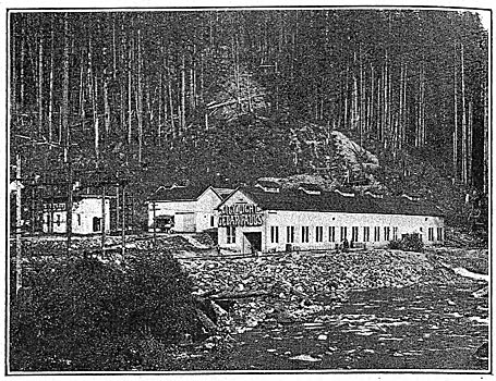
From the present dam two penstocks, one 68 in. and the other 49 in. in diameter, convey the water to the power house, 3 1/2 miles distant and 610 ft. lower in elevation. These pipes are of wood-stave construction for a distance of 15,600 ft., and from this point to the power house, 1000 ft., riveted steel is used. The larger pipe divides through a Y and connects to two 48-in. steel pipes. Both penstocks are covered throughout with 18 in. of earth and the steel portions are anchored at short intervals in heavy blocks of concrete. Many engineering difficulties were met in laying the penstocks, and it was necessary to use five steel elbows for the larger pipe, where the curvature could not be kept under 18 deg., the maximum used with wood-stave pipe. Where it was necessary to cross the river steel pipe is carried 4 ft. below the bed of the stream so that there is no danger from floods, which are quite severe in the Cedar River valley. Each penstock has a 30-in. standpipe, located at the top of the hill about 3600 ft. from the power house. Although situated so far from the station, these pipes are an aid to regulation, as their frequent overflow would indicate. There is a cross-over connection between the pipes just above the power house, so that either pipe may supply any waterwheel.
GENERATING STATION.
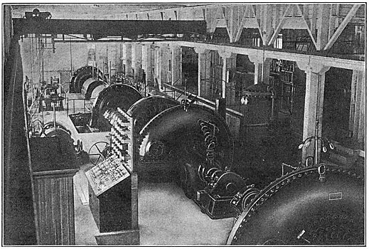
The generating station contains four units, two 2400-hp Pelton impulse wheels direct-connected to 1500-kw, 60-cycle, 2300-volt, three-phase Bullock generators, and two 8000-hp Francis turbines, built by the Platt Iron Works, connected to 4000-kw, 400-r.p.m., 60-cycle, 2300-volt, three-phase Westinghouse generators. Each impulse wheel has two runners, both equipped with needle and deflecting nozzles and governed by a Lombard-Replogle mechanical governor acting on both nozzles. The turbines, which were among the first in America to be installed on so high a head, are equipped with Lombard type N governors and relief valves, the latter being arranged to open automatically on a certain pressure in the penstock and to be closed by the governor, to which they are attached by a dash-pot connection. The problem of regulation on the turbines is made difficult by the long penstock and high head, coupled with the fact that it was not feasible at the time the station was built to place a standpipe near the power house. The governors and relief valves have given good results, however, and the governing for the station is done largely with the turbines rather than with the impulse wheels. Each impulse wheel has a 24-in. motor-operated gate turbine has a 48-in, hydraulic gate valve.
| |||
| Fig. 4 - Interior of Generating Station at Cedar Falls. |
| |||
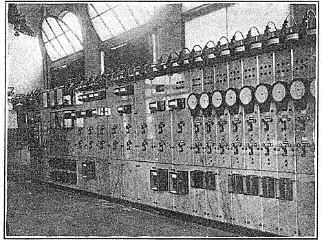
| Fig. 5 - Swtichboard at City Substation. |
| |||
| Fig. 6 - Control Board at Cedar Falls. |
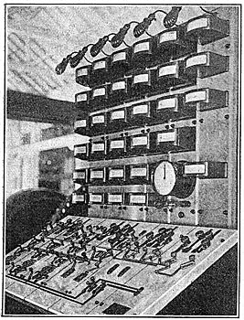
Control of the entire station is brought within the reach of one operator by means of a special control board, 36 in. by 72 in. in size, designed and built by the lighting department. This board contains a diagram of the entire station, gun-metal being used to represent waterwheels and generators; nickel, exciter circuits; brass, the 2300-volt circuits, and copper, the 60,000-volt circuits. The diagram is so arranged that each operation is seen in miniature on the face of the board, rendering confusion or mistake improbable. The meters and synchroscope are mounted on vertical panels immediately above the control board. As a safeguard in case the load drops off suddenly, three rheostats made of coils of resistance wire immersed in water have been installed, which can be connected to the station bus or to any machine and thus prevent excessive speeds.
| |||
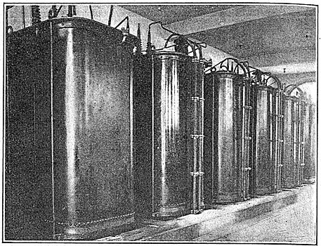
| Fig. 7 - Transformers, Substation in Seattle, Municipal System. |
| |||
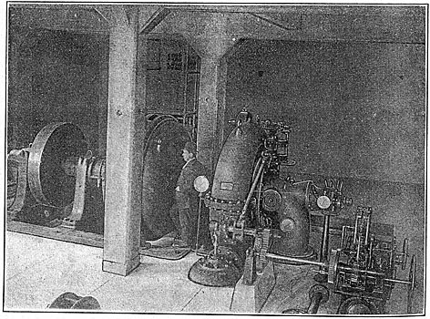
| Fig. 8 - Lake Union Auxiliary Generating Station. |
The generating units are placed end to end down the center of the station, with the control board on one side and the 2300-volt switches on a balcony opposite, together with the field rheostats and switches. For transmission the potential is stepped up to 60,000 volts. There are nine 1500-kw step-up transformers grouped in three banks, connected in delta on the low-tension side and in star on the high-tension side, with the neutral point of the star connection grounded. The transformers are placed in a separate building next to the power house, and the high-tension wiring is placed in another building, except the line switches, which are in a separate small stone building. A duplicate bus system is used throughout, on both 2300-volt and 60,000-volt wiring.
The 2300-volt switches are non-automatic; but the high-tension lines have a relay of special design, consisting of two solenoids acting on a common core and so arranged that an excess of current in either will pull the core to its end. Each solenoid is connected through a series transformer to one of the wires of each transmission line, the ratio on the series transformer being adjusted to balance the relay when the lines are operating normally, in multiple. Reverse-power time-limit relays are used at the substation. In case of short-circuit on either high-tension line the power-house relay will remain balanced until the reverse power relay clears the faulty line at the substation. This will unbalance the power-house relay, which will indicate to the operator by a signal lamp which line is in trouble.
TRANSMISSION LINES.
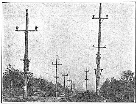
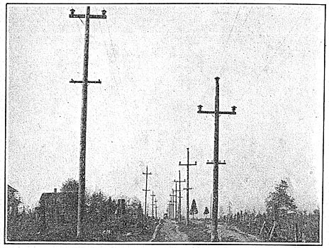
The two transmission lines are 38.7 miles in length, built of cedar poles, using 14-in. triple-petticoat insulators on steel pins. The first line, built in 1904, is of No. 2 solid copper, spaced on a 6-ft. triangle, and the average span length is 140 ft. The second line, built four years later, uses No. 4-0 stranded copper, spaced on a 7-ft. triangle, and is strung on cedar poles 55 ft. to 85 ft. long with 11-in. tops, the poles being spaced at from 150 ft. to 250 ft.
| |||
| Fig. 9 - Transmission Line, Seattle Municipal System. |
| |||
| Fig. 11 - 80,000-Volt Line, Seattle Municipal System. |
Each high-tension line has a lightning arrester at each end, consisting of a horn-gap in series with a water column. A complete telephone system is installed from the city to Cedar Lake. The new transmission line carries a telephone line of 3/16-in. stranded steel cable, strung 15 ft. below the high-tension wires, and the old line has a similar line of No. II copper. The telephone lines are transposed every 3000 ft. and the high-tension lines every 12,000 ft. Special telephone transformers with grounded secondaries, developed and made by the lighting department, are used for all telephones.
 |
| Fig. 10 - Wiring Diagram of Main Circuits of Seattle Municipal Light and Power System. |
To insure continuity of service, the entire right-of-way for the transmission lines has been cleared, bringing the lines beyond the length of the tallest tree. This made necessary the cutting and clearing of millions of feet of fir and hemlock. Each line is divided into three sections, with disconnecting and cross-over air switches, so that any defective section can be cut out. Two line patrolmen are stationed at points a third of the way from the ends of the line and patrol the line twice a week. The patrolmen's cottages are lighted from a special 5-kw, 32,400-volt to 12-volt transformer built in the department shops, the primary side being connected between one wire of the transmission line and the ground.
AUXILIARY GENERATING STATION.
An auxiliary generating station containing a 2500-hp Francis water turbine direct-connected to a 1500-kw, 60-cycle, 2300-volt, two-phase generator is situated at the foot of Nelson Place in the city. This station uses the overflow from the Volunteer Park reservoir of the Seattle Water Department, which is located on the hill above the plant. The head available is 412 ft., and there is sufficient waste water to run the plant continuously at full load if desired. The auxiliary plant is not only useful to increase the total generating capacity but will be ready in case of accident to the main station and will materially help to tide over the dry seasons until the new darn is completed.
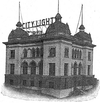
SUBSTATION.
The city substation, situated at Seventh Avenue and Yesler Way, is a white brick and concrete building with two stories and a basement. There are placed eight 1500-kw transformers arranged in four banks and connected to give 15,000 volts and 2400 volts two-phase on the low-tension side, using the T method of connection. These transformers, which are similar to those at the generating station, are of the water-cooled type insulated with solid micanite throughout. The low-tension winding is divided into six coils, which may be connected in multiple for 2500 volts or in series for 15,000 volts. At present two banks are used on each voltage. The transformers, operating switchboard and a 750-hp synchronous motor-generator set, are located on the first floor of the substation, the 60,000?volt and 15,000-volt wiring and switches are on the second floor, and the 2500-volt wiring and switches, feeder regulators and transformers for the street-lighting circuits are in the basement.
The switchboard, designed and built by the lighting department, is of the remote-control type and carries no potential higher than 125 volts either for commercial or street lighting. It contains panels for the two transmission lines, for four two-phase banks of transformers, for four 15,000-volt and fourteen 2400-volt feeders, for twelve street-lighting transformers and for the motor-generator set and four direct-current feeders. Each transmission-line panel carries a Westinghouse curve-tracing wattmeter and power-factor meter, and a similar voltmeter and frequency meter is used on the station bus. The high-tension line relays are of the reverse-power, inverse-time-limit type and are connected through special series transformers to the lines.
These transformers made in the department shops have a single turn on the primary, and a porcelain tube such as is used for oil-switch bushings separates the primary from the rest of the transformer. A spark-gap is connected in parallel with the primary of the transformer, set at 1/16 in., so that a surge on the line cannot injure the primary winding.
All switches in the station, like those at the generating station, are remotely controlled. The main transformer switches are non-automatic; all the others have relays, mounted on the board. The 15,000-volt lines have overload relays set to operate in three seconds. Each wire is connected through a series transformer to a solenoid which closes a direct-current circuit through a master solenoid, which in turn opens the switch after a time interval determined by the setting of a dashpot attached to the master-solenoid core. Each of the 2400-volt feeders has an instantaneous overload relay. Duplicate buses are used throughout the station so that any part of the wiring may be disconnected without interrupting service. A complete and continuous record of operation is assured by the use of graphic meters. A record of grounds on the 2400-volt feeders is also kept. Each wire of the 2400-volt bus is connected through the primary of a twenty-to-one transformer to the ground. The secondary of each of these transformers is connected to a recording voltmeter and an indicating lamp in multiple. This arrangement has proved of value several times in helping to locate trouble too slight or intermittent to be noted on the ground lamps by the operator.
Bus voltage is regulated by a Tirrill regulator working on the exciter of the 750-hp motor. This motor drives two 1000-amp, 250-volt direct-current generators which supply a distribution system covering the entire business district, serving elevator motors principally.
Energy enters the substation through the two transmission lines and passes to the oil switches on the second floor. These switches, of the same type as those used at the generating end of the line, are of the round-tank, horizontal-break type and have opened the line on severe shorts without difficulty. Lightning arresters of the horn-gap type with a water column in series are mounted on a rack outside the station. The interior high-tension wiring is carried by a rack made of gaspipe. Each oil switch has disconnecting and short-circuiting air switches so that the oil switch may he cleared for repairs at any time. Disconnecting switches, also air-break, for each step-down transformer are placed on the interior wall of the station. From the step-down basement, while the 15,000-volt wires return to their oil switches on the second floor. All 2500-volt wiring in the station is thoroughly insulated with varnished cloth, and the busbars are first wound with asbestos strips and then with varnished cloth. Low equivalent lightning arresters are used on each bank of transformers, as well as on the 2500-volt buses. Energy for switch control and meters is furnished by a 25-kw motor-generator set supplying 125-volt direct current. A small storage battery of the nickel-iron type is also installed, to insure light and control in case of a shut-down. A complete system of decorative lighting outlines the substation at night, so that it can be seen for miles. Three 50-kw transformers are used to supply these lamps and the inside station lamps and small motors.
DISTRIBUTION SYSTEM.
Radiating from the main substation are four 250-volt direct-current feeders, twenty-one series street circuits, twelve 500-kw, 2400-volt feeders and three 15,000-volt feeders. The 15,000-volt system, which supplies three outlying substations and a number of large mills and factories, is unusual from the fact that it is a two-phase system and that the neutral of each of the two phases is grounded. This makes a five-wire, two-phase system, in reality giving four 7500-volt circuits. The choice of this system was made on account of the great waterfront of Seattle, which totals 27 miles, and the fact that the principal factories and Mills of the city are located along this waterfront. The city is 20 miles in length and to serve these industries at 2500 volts from substations would require an enormous outlay of copper. Some system was desired by which such large concerns could be served from the 15,000-volt lines directly using pole-type transformers. The three-phase, four-wire system had the disadvantage of requiring three transformers for each installation, and the two-phase system was designed to meet the special conditions of distribution in the city. By means of this system it is possible to use 7500-volt transformers of the pole type, connected between the neutral and one outside wire.
Where the lines enter a substation the neutral is omitted and 15,000-volt transformers are used. For 35,000-volt or 7500-volt underground work and for the 15,000-volt submarine cable to West Seattle, in salt water, it will be noted that the greatest voltage to the cable sheath will be 7500, though the transmission voltage may be 15,000. The system is very flexible, and during the construction of the lines, in several places where the neutral was omitted, both single-phase and two-phase, 7500-volt services were installed, using the ground as a return in emergency. This gave no difficulty, as the high voltage and consequent small current caused no trouble from earth contact and, being alternating, gave no trouble from electrolysis. As an example of this, the large steel works at West Seattle are operated two-phase, two-wire, with the other terminal of each transformer grounded, while the entire suburb of South Park, 7 miles distant from the substation, is operated over a single wire. The elimination of large motor loads from suburban substation circuits leaves a much steadier lighting load and admits of excellent regulation by the use of automatic regulators. All secondaries of both the 7500-volt and 2500-volt systems are grounded at the neutral or some other point, and the grounded wires are joined into one complete network over the entire city. One ground is placed at each transformer, and large grounds are placed in the salt water and other wet places. These grounds are made with large copper sheets and coke in some places, and from broken lengths of cast-iron water pipes when these are available.
For lighting and smaller motor loads the 2500-volt, two-phase system of feeders is used. Twelve of these feeders are taken from the main substation for the central part of the town, three from the Fremont substation for the north end, one from the Hillman substation for the south end, and one from the West Seattle substation for West Seattle. These feeders, which are of 200-amp and 150-amp rating, are equipped with automatic regulators of the variable-ratio type, with contact-making voltmeters set to give a constant voltage at the receiving end of the feeder. Since large motor loads are cared for by the 15,000-volt system, it is possible to maintain a close regulation on these feeders. The wire used for the primaries varies in size from No. 2-0 to 350,000 circ. mils, while the secondaries are usually of No. 4, with No. 6 for the neutral and No. 8 for the services. Pole-type transformers are used varying in rating from 272 kw to 50 kw. From four to twelve are usually connected in one bank on the secondary side. This distribution system serves approximately 20,000 customers, scattered over a territory nearly 20 miles long and 30 square miles in area.
STREET LIGHTING.
The series street lighting system is divided into twenty-nine circuits connected two in series to General Electric 6.6-amp, 100-lamp, air-cooled, constant-current transformers. Each transformer has been fitted with a small solenoid-controlled oil switch on the primary side, controlled from the switchboard. The secondary ammeters are also placed on the board, being connected to the circuit through a one-to-one series transformer. Each arc transformer has a pair of signal lamps controlled from the board so that the operator may adjust the secondary current by signaling to the oiler. A disconnecting and short-circuiting board with plug switches, made in the lighting department shops, is used on the secondary side of each transformer. On the series circuits 6.6-amp arcs are used in series with 40-cp tungsten lamps and 3oo-cp tungsten lamps. The Seattle Lighting Department has been a pioneer in the use of tungsten lamps for street lighting, having placed an advance order with the manufacturers for the first 6.6-amp tungsten lamps marketed. These were so satisfactory that a larger unit of the same type was sought, with the result that 6.6 amp, 55-volt, 300-cp tungsten lamps, manufactured especially, for the department, are rapidly displacing the arc lamps. These large lamps average to date over 2000 hours of life and give very satisfactory illumination, while comparing very favorably with arc lamps in operating expense. In all 700 arc lamps are used on Seattle's streets, with 210 3oo-cp tungsten lamps and 5315 40-cp tungsten lamps.
ORNAMENTAL BUSINESS AND RESIDENCE DISTRICT LIGHTING.
The business district of Seattle, as well as several of the better residence districts, is lighted by a system of ornamental cluster lamps of original design developed by the lighting department. The pole used in the business district is of cast iron, weighing 650 lb., and carries five globes placed in a triangle in a plane perpendicular to the curb line, with a to-in. globe at the top, two upright globes below and two 12-in. pendent globes at the lower corners of the triangle. The globes have a light sand-blast finish. The unique arrangement o f the lamps gives a pleasing decorative effect and at the same time secures good distribution of light on the street. With five 50-watt tungstens to a pole and a spacing of 90 ft., the poles being placed opposite each other at the curb line, the intensity of illumination varies from 0.32 ft.-candle to 0.79 ft.-candle on the sidewalk and from 0.34 ft.-candle to 0.45 ft.-candle at the center line of a 90-ft. street. Each pole has a 250-watt, 120-to-8-volt transformer in the base, and the lamps are 8-volt, 50-watt tungstens, designed especially for the department.
The mains are of lead-covered cable and are placed underground near the curb line, in fiber conduit incased in concrete. Manholes for the 2500-to-250-volt transformers are placed beneath the sidewalk at street corners.
 |
| Fig. 12 - Connections of 15,000-Volt Distribution System. |
 |
| Fig. 13 - Total Candle-Power for Street Lighting. |
 |
| Fig. 14 - Maximum and Average Output and Load Factor 1905-1911. |
 |
| Fig. 15 - Wiring Diagram of A Street-Lighting Pole. |
For residence districts a cluster pole similar to the five-globe poles is used, but having three upright globes. These poles carry three 50-watt lamps of the type already described. They are placed alternately on opposite sides of poles on the same side of the street. For parks and drive-ways a pole with one 20-in. globe and a single the street and are spaced from 150 ft. to 200 ft. between 75-watt, 1272-volt lamp is used. Altogether, there are in Seattle 1116 five-globe posts lighting 13 1/2 miles of street, 378 three-globe posts lighting 8 1/2 miles of street and 137 one-globe posts lighting 3 miles of street.
 |
| Fig. 16 - Daily Winter and Summer Load Curves. |
 |
| Fig. 17 - Rates for Lighting and Motor Service. |
OUTPUT.
Typical load curves at the city substation are shown in Fig. 16, and Fig. 14 gives data on the average and maximum load by months since the plant started, as well as the load-factor for the same period. The load-factor during 1909 and 1910 was exceptionally high, owing to the fact that the plant supplied 1500 kw continuously to pump motors used in sluicing the immense Denny Hill regrade, finished in 1911. The curve showing the increase in candlepower of street lamps gives some idea of the growth of the city and the extension of the street-lighting system necessary to keep it well lighted. The daily load curves emphasize the great difference in summer and winter loads and call to mind the fact that Seattle is one of the most northerly cities in the United States proper.
 |
| Figs. 18 to 21 - Day and Night Views of Seattle, Showing Tungsten Street Lighting With Three-Lamp Posts in Residential Section and Five-Lamp Posts in Business Section. |
RATES.
Rates for electrical energy in Seattle are very low, ranging- from 6 cents per kw-hr. for residence lighting to less than 1 cent for large motor loads. The municipal rates are computed from logarithmic curves, which give a decreasing rate with the increase in the number of hours' use of the load during the month, or, in other words, with the load factor. Fig. 17 shows the rates used for business and motor loads. Residence rates are 6 cents per kw-hr. for the first 60 kw-hr. used in the month and 4 cents per kw-hr. for all used in excess of 60 kw-hr. The department sells tungsten lamps to its customers at cost, and tungsten lamps of all sizes are gradually replacing other lamps. About 90 per cent of the houses in Seattle are wired for electric lighting, which is used in residences almost to the exclusion of other light.
|
The municipal light and power plant is owned by the city of Seattle and is operated by the lighting department under the direction of Superintendent J. D. Ross. Mr. Ross has been successively designing and constructing engineer, chief electrical engineer and superintendent of the plant. Most of the men in charge of the various departments of the plant, as well as many of the employees, have been with the organization since the plant started in 1905. The lighting department maintains a well-equipped machine shop where all kinds of repairs are made. Here, also, are made all instrument transformers, both series and shunt, for potentials up to 60,000 volts, small eight-volt transformers for the cluster-lamp posts, oil switches of all sizes, switchboards for all the stations, relays, lightning arresters and other apparatus.
