[Trade Journal]
Publication: Electrical World
New York, NY, United States
vol. 59, no. 22, p. 1191-1196, col. 1-2
WESTERN TRANSMISSION SYSTEMS.
A Brief Review of Western High-Tension Systems Giving the Important
Features Pertaining to Each One.
The Pioneer System and the Most Extensive System in the World Among Those Utilizing the
Water-Powers of the Western Mountains—Comparative Data on All
High-Tension Systems of the World.
DELEGATES to the National Electric Light Association convention from points east of the Mississippi, visiting the western portion of our country for the first time, will be impressed with the magnitude of the electrical transmission systems throughout this territory, and will be especially interested to learn of the features of similarity or marked difference between the important Western and Eastern systems. The present article contains therefore brief notes on many of the prominent Western transmission systems and items for comparison purposes on all transmission systems elsewhere operating at 100,000 volts or more.
A feature seldom considered in Eastern transmission systems, but which is often of predominating importance in Western systems, is that of irrigation, with which electrical energy transmission is closely associated throughout all sections of the West. In many cases the transmission undertaking would have been impracticable had not the irrigation project been a necessity. In other cases the load on the transmission system supplied by irrigation pumping is the deciding element in the success of the transmission project.
At Roosevelt, Ariz., about 70 miles northwest of Phoenix, is located one of the largest dams in the world, having a maximum height of 280 ft. and a length of crest of 1080 ft. This dam was constructed by the United States government primarily for supplying water to irrigate arid lands, but use is also being made of the dam in connection with a transmission system for supplying energy for pumping water from wells in the Gala River Indian reservation and in Salt River Valley, as well as for industrial purposes at Phoenix, Ariz. This system was described in our issues dated July 7, 1910, and March 30, 1911.
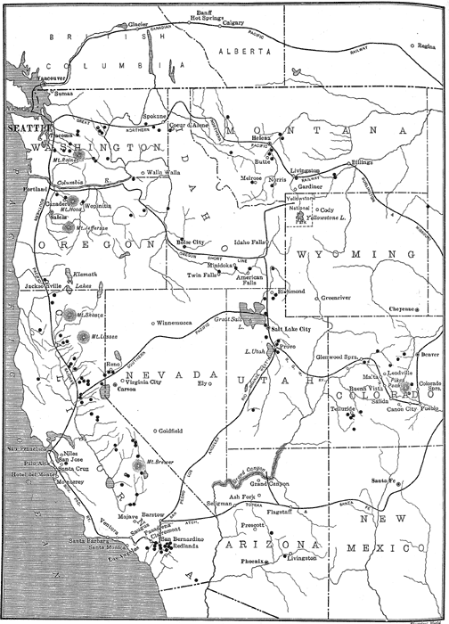 |
| Fig. 1 - Map Showing Locations of Important Western Hydroelectric Developments and the Routes Covered by Delegates to the Seattle Convention. |
Electrical energy as a by-product will figure conspicuously in the municipal aqueduct installation at Los Angeles, Cal., which is now under construction. The aqueduct, which will be 250 miles in length, is being built primarily to supply water for the city, but the natural fall of the water throughout its travel will be utilized to produce electrical energy for transmission to Los Angeles. The preliminary arrangements for the aqueduct undertaking were outlined in our issue dated May 4, 1911, while in the issue of Feb. 10, 1912, the whole system was illustrated and described in detail.
The limitations imposed by and the advantages derived from the combination of irrigation and hydroelectric undertakings are strikingly shown by the conditions surrounding the utilization of the limited supply of water around Los Angeles. Both the Pacific Light & Power Company and the Southern California Edison Company operate hydroelectric stations on the Santa Ana River, where all of the water is used for irrigation and the flow must be maintained constant. The waterwheels are equipped with deflecting nozzles, so that no change in flow can take place. Moreover, the generators are so operated as to carry at all times such a load as will fully utilize the power in the water to the best advantage. These plants are interconnected with other hydroelectric plants and steam plants which take care of all load fluctuations. The Southern California Edison Company operates in its system one hydroelectric station on Mill Creek, subject to irrigation restrictions, where the effective hydraulic head at the wheels is approximately 1960 ft.
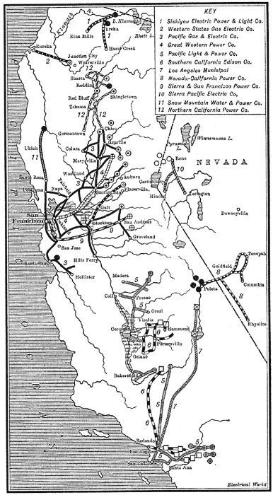 |
| Fig. 2 - Transmission Systems in California and Nevada. |
Both the Southern California Edison Company and the Pacific Light & Power Company transmit energy to Los Angeles and the surrounding country from stations located on Kern River, about 125 miles distant from the city. A large portion of the load on the systems of each of these companies is represented by irrigation pumping, industrial motor and railway service. However, the Pacific company has a large railway load and the Edison company a large lighting load. The transmission systems of these two companies have been referred to frequently in our columns, and were fully described in the issue dated Oct. 28, 1909. The early development of the Pacific system was described on April 6, June 29, and Sept. 7, 1901; the development of the Edison system, which (4-5 missing words) plant of the country, was covered in issues dated Feb. 25, March 4, March 11 and March 25, 1905, and Aug. 31, 1907. Auxiliary oil-burning stations are used with both systems, the Pacific station having been described on Sept. 12, 1908, and the Edison on March 9, 1912.
One of the most important hydroelectric transmission systems now under construction is that of the Pacific Light & Power Company on Big Creek, 6o miles east of Fresno, from which energy will be transmitted 275 miles to Los Angeles. The water will be utilized under heads of from 1900 to 2100 ft. to produce ultimately more than 100,000 kw.
A system the main business of which is supplying energy to types of load seldom encountered in the East is that of the San Joaquin Light & Power Corporation, in Central California, which is closely affiliated with the Pacific Light & Power Corporation. The company operates 60,000-volt and 30,000-volt circuits for distributing energy for pumping oil for fuel and water for irrigation. Notes on this development appeared in our issues dated Sept. 23, 1905, and Aug. 4, 1910.
Among the prominent interstate transmission systems, mention should be made in this connection of the installation of the Nevada-California Power Company, which transmits energy from hydroelectric stations on Bishop's Creek, a tributary of Owens River, California, over 60,000-volt circuits about 100 miles to Tonopah, Goldfield and other mining districts in Nevada. This system will soon be interconnected with a transmission system now being erected in southern California to join one of the most extensive systems in the State.
In a state renowned for the extent of the transmission systems within its borders the Pacific Gas & Electric Company holds the record of operating the greatest number of interconnected circuits, the largest number of hydroelectric plants and the pioneer hydroelectric plant in America. Its circuits cover about 1200 miles, receiving energy from three steam and eleven hydroelectric stations, namely Alta, Auburn, Centerville, Colgate, Deer Creek, De Sabla, Electra, Folsom City, Nevada City, Newcastle and Yuba City. Articles relating to the early developments appeared in our issues dated Feb. 16, 1901, June 8, 1901, and Aug. 5, 1905. The second article contains a description of the 4427-ft. span across the Straits of Carquinez — the longest span in the world. The present constructive features and operating characteristics of this system are described in an article in this issue.
The feat of spanning the Straits of Carquinez by electric circuits, mentioned above, has been equaled more recently by the crossing of the San Francisco Bay by a submarine 12,000-volt, three-phase cable 18,800 ft. in length, placed in service by the Great Western Power Company during the present year. This company operates in its Feather River plant reaction turbine units of the extremely large size of 18,000 hp, utilizing a head of 525 ft., making a record for this type of wheel. Articles relating to this system appeared in our issues dated Aug. 26, Sept. 16 and Sept. 23, 1909, and July 8, 1911.
Prominent among the long-distance straight-away transmission systems is the Stanislaus development of the Sierra & San Francisco Power Company. This system operates at 104,000 volts to transmit energy from a 1500-ft. head hydroelectric station on the Stanislaus River 138 miles to San Francisco for use by the United Railways Company. In this system extra care has been exercised to obtain water storage for enabling the plant to utilize the average daily flow. For this purpose there was built a rock-filled restraining darn 140 ft. in height-the largest dam of its kind at the time it was constructed. An article relating to this system appeared in our issue dated Sept. 26, 1908.
An excellent example of the series operation of hydraulic equipments driving parallel-connected electrical equipments is found in the hydroelectric system of the Northern California Power Company, which owns five separate hydro-electric stations located upon Battle Creek and its tributaries. The system represents the acme of simplicity, both in construction and in operation. Automatic governors are used on the waterwheels, but with this one exception the entire system is hand-operated. The early plants were described in our issues dated Sept. 10, 17, 24 and Oct. 1, 1904, while the latest installation was described on Feb. 3, 1912.
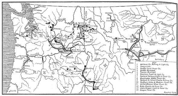 |
| Fig. 3 - Transmission Systems in Oregon, Washington, Idaho and Montana. |
One of the most progressive public-service companies in Oregon is the Portland Railway, Light & Power Company, which obtains its energy from several steam plants and from low-head hydroelectric stations on Willamette and Clackamas Rivers and Silver Creek. The early plants were operated at 33 cycles, but this frequency has gradually been abandoned in favor of the present standard 60 cycles. Between the newest 10,000-kw station at River Mill and the Lincoln substation in Portland the distance is only 28 miles, but the company has found it desirable to erect a high-class 60,000-volt transmission circuit supported on steel towers over this route. Articles on the systems of this company appeared in our issues dated July 29, 1905, April 11, 18 and 25, 1908, July 15, 1909, and Dec. 23, 1911.
Details of the hydroelectric and steam plants along the Puget Sound region of Washington are given elsewhere in this issue. However, mention should be made here of the unique Snoqualmie Falls plant which is located in a chamber blasted out of the solid rock 260 ft. under the bed of the stream above the falls. This plant was described in our issues dated Oct. 21, 1899, Sept. 14, 1901, May 7, Oct. 1 and Oct. 8, 1904. Attention should also be directed to the 20,000-hp high-head reaction turbines, the largest of this type ever designed, in service in the White River plant, as stated elsewhere in this issue.
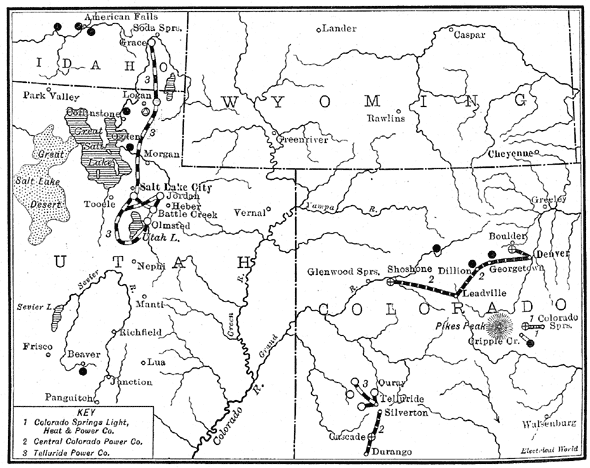 |
| Fig. 4 - Transmission Systems in Idaho, Utah and Colorado. |
By far the largest hydroelectric Washington is that of the Washington Water Power Company, which operates plants at Spokane and Little Falls on the Spokane River, representing a combined development of 133,000 hp, in addition to a plant at Post Falls, Idaho, on the same river, having a rating of 18,000 hp. The company operates more than 500 miles of 60,000-volt transmission circuits for supplying energy for mining, agricultural, industrial, railway and lighting purposes. Articles relating to the system of this company appeared in our issues dated May 23 and 28, 1908.
Of the few low-head hydroelectric developments in the West, one of the most important is that of the United Missouri River Power Company, Helena, Mont., which operates a 12,000-hp plant under a 32-ft. head at Canyon Ferry and a 25,000-hp plant under a 70-ft. head at Hauserlake. The original dam at the latter place was built of structural steel resting on a concrete pad laid over sheet piling. The dam was 490 ft. long and contained about 1200 tons of steel. The central portion of this dam became undermined in April, 1908. This dam was replaced in 1911 by a concrete structure containing 85,000 cu. yd. of material. The hydroelectric installations at Canyon Ferry and Hauserlake and the transmission systems were described in our issues dated July 13, 1901, June 7, 1902, Aug. 9, 1902, and May 23, 1908.
Chief interest in the equipment of the Great Falls Power Company, which is controlled by the Butte (Mont.) Electric & Power Company, centers around the fact that an emf of 100,000 volts is employed. The straight-away distance of transmission from the generating station at Great Falls to the substation at Butte is 130 miles. Along the route of the transmission system between these places are two separate tower lines on the same right-of-way, making 260 miles of circuit to the substation. From this substation extends a 22-mile line to Anaconda, so that the total distance of transmission is 152 miles and the total length of circuit in use 282 miles.
Each tower supports three No. 0 hemp-core six-strand copper conductors in a horizontal plane with 10 ft. 4 in. spacing between adjacent wires. For carrying the conductors below the horizontal cross-arm use is made of six suspension insulator disks 10 in. in diameter. Under rain test the insulator series of six disks withstand 300,000 volts, thus providing a factor of safety of 3 for insulation. For protection against lightning two grounded wires of 3/8-in. seven-strand Siemens-Martin steel are placed symmetrically above the transmission conductors. At the two ends of the transmission line and at its middle are installed aluminum cell arresters which protect the line from both internal and external disturbances.
The chief hydroelectric installation is at Rainbow Falls, where with a fall of 105 ft. and a flow of about 2300 cu. ft. per second at low water a minimum of 27,500 hp is available without storage. The plant equipment consists of six 6000-hp turbines, each driving a 3500-kw, three-phase, 60-cycle. 6600-volt generator. Two of the generators deliver energy at 6600 volts directly to circuits distributing energy in the vicinity of Great Falls. Four banks of transformers are installed to raise the emf of the energy from the other generators to 100,000 volts. These transformers are delta-connected on both the primary and the secondary sides. In the substation at Butte are four transformer banks similar in every respect to those at the generating station, but arranged to deliver the energy at 2500 volts. A note-worthy feature of the station is the arrangement of the high-tension circuits. The three leads of each circuit are placed in a single vertical plane, each one being supported from the one above by means of standard disk-like insulators. The leads are built of 15-in, iron pipe, arranged as duplicate buses in order to provide for ease of control. Energy is transmitted beyond Butte without transformation to operate the Washoe copper smelter at Anaconda.
Not the least interesting feature of the Great Falls system is the character of the load carried. It is claimed that the load-factor is more nearly 100 per cent than is true of any other plant in this country. Moreover, the power-factor, which is under control, is kept at practically 100 per cent. The energy is used chiefly for operating copper smelters and motor-driven air compressors used in mines. The air-compressor motors are of the synchronous type, and hence the power-factor can readily be adjusted to any desired value. Articles on this system appeared in our issues dated Jan. 26, 1901, Dec. 23, 1909, and July 8, 1911.
In southern Idaho the United States Reclamation Service operates its Minidoka irrigation project, which is the largest pumping system thus far undertaken. Water is lifted about 66 ft. for irrigating 48,000 acres of land. The hydroelectric installation is located on the Snake River and has a rating of 70,000 hp. It supplies energy over 38 miles of 33,000-volt circuits largely for purposes of irrigation. This system was described in our issues dated July 7, 1910, and Dec. 30, 1911.
It is a remarkable fact that two of the largest hydroelectric stations in Idaho supply energy over long-distance transmission lines to points in adjacent states. Reference has already been made to the 18,000-hp Post Falls (Idaho) station of the Washington Water Power Company. The Telluride Power Company operates at Grace, Idaho, a station of almost identical rating on the Bear River, from which energy is transmitted into Utah. The latter station is operated in parallel with hydroelectric stations at Provo, Jordan Narrows, Logan and Battle Creek in Utah, interconnected by means of more than 500 miles of 44,000-volt, 60-cycle circuits. The Grace plant is arranged for seasonal storage; the Logan plant is the only one operating with automatic governors, the other plants being hand-controlled in order to simplify operation and to comply with the governmental restrictions as to uniformity of flow of water in the irrigation ditches. The plant at Battle Creek operates under the high head of 1630 ft. This system was described in articles in our issues for July 15, 1909, Nov. 25, Dec. 9, Dec. 16 and Dec. 23, 1911. The Telluride Power Company operates in Colorado an entirely separate hydroelectric system which is noteworthy as having been the first system to operate at an emf as high as 40,000 volts, the highest emf in use prior to its installation being 15,000 volts. This pioneer system was described in our issue for Nov. 18, 1911. An interesting Colorado hydroelectric system is that operated by the Colorado Springs Light, Heat & Power Company, which obtains energy from a plant at Manitou operating under the record high head of 2,300 ft. This system was described on July 3, 1905, and May 26, 1906.
Among the transmission systems of the West perhaps none is more interesting than that of the Northern Colorado Power Company, which operates 44,000-volt circuits covering a territory of nearly moo square miles north of Denver, the energy being used largely for pumping water from underflow for purposes of irrigation farming. Incidentally it should be noted that the energy is not obtained from water falls, but from lignite coal which cannot withstand exposure to the atmosphere and hence is consumed at the mines where the generating plant is located. The operation of this important electric irrigation undertaking was fully set forth in our issue dated Sept. 30, 1911.
By far the largest hydroelectric equipment in Colorado is that of the Central Colorado Power Company, the system of which is noteworthy not so much on account of its size as by reason of the extremely mountainous character of the country traversed by the transmission lines, the high altitudes reached and the severe climatic conditions encountered. The 100,000-volt circuit of this company crosses the Argentine Pass at an elevation of 13,700 ft. and is subjected at times to a wind velocity exceeding 150 miles per hour. Articles relating to this system appeared in our issues dated Jan. 27, March 9, June 23, June 30 and July 14, 1910; July 8 and Oct. 7, 1911. An article covering the severe conditions under which this system operates appears in this issue.
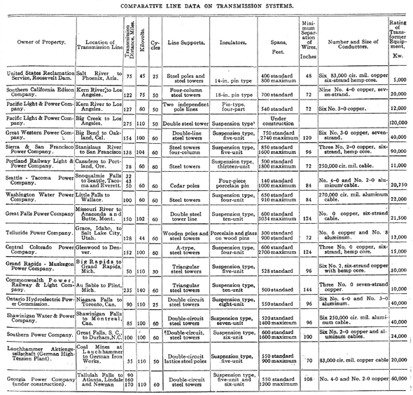
Considerable data on many of the Western transmission systems mentioned above are given in the accompanying table. For comparative purposes the table contains also data on other transmission systems throughout the world operating at not less than 100,000 volts. Articles relating to these systems have appeared in our columns as follows: Grand Rapids-Muskegon Power Company, Sept. 14 and Nov. 2, 1907, Feb. 4, 1909, and Sept. 16, 1909; Commonwealth Power, Railway & Light Company, July 14, 1910, and April 13, 1912; Ontario Hydroelectric Power Commission, Aug. 26, Sept. 2, and Sept. 9, 1905, Jan. 6, Jan. 13, Jan. 20 and Jan. 27, 1912; Shawinigan Water & Power Company, Feb. 8, 1902, Dec. 9, 1911, and May 4, 1912; Southern Power Company, March 9 and March 24, 1910, July 1 and July 8, 1911; Lauchhammer Aktiengesellschaft, Oct. 28, 1911.
 |
Many valuable data on hydroelectric developments throughout the United States were given in a recent report of the Commissioner of Corporations. In this report it was shown that of the total available water-power in California of 1,170,000 hp, 430,000 hp is being utilized for producing electrical energy and 730,000 hp remains undeveloped. In Oregon the values are 96,000 hp utilized of a total of 240,000 hp available. Washington utilizes 300,000 hp of a possible 416,000 hp. Idaho utilizes 52,000 hp of 94,000 ho available, Montana 140,000 hp of 245,000 hp available and Colorado 70,000 hp of the possible 129,000 hp. An article on this report appeared in our issue dated May 11. 1912.
|

