[Trade Journal]
Publication: Electrical World
New York, NY, United States
vol. 59, no. 22, p. 1197-1204, col. 1-2
WORLD'S LARGEST TRANSMISSION SYSTEM.
An Outline of the Operating System and Service Conditions of the Pacific Gas & Electric Company.
Nearly 1,200 Miles of 60,000-Volt CircuitsTotal Output About 400,000,000 kw-hr. per YearHydro-electric Plants at De Sabla, Colgate, Electra, Centerville, Folsom and Other Places, Aggregating 66,810 kw.
THE most striking example of the centralized production, transmission and distribution of electrical energy upon a great scale to be found outside the half-dozen principal cities of America is afforded by the system of the Pacific Gas & Electric Company, of California. Few engineers who have not visited the Pacific Slope realize the magnitude of the company's development, the area covered by its markets or the great extent attained by its operating organization. To tell fully of the development of the electric service industry in central California would require a history of the growth of the State in population, agriculture, mining and manufacture for the past fifteen years. From small beginnings in scattered localities the present vast network of central-station service has been evolved through growth of business, the development of the natural resources of the State, combination of plants and lines, standardization of operating methods and progressive administration. At the bottom of the economic situation lies that great incentive to hydroelectric enterprise, high cost of coal. Even the discovery of fuel oil within the State has served only to reinforce the value of transmitted water-power along the lines of securing highly efficient and reliable operation in auxiliary steam plants.
|
The Pacific Gas & Electric Company owns property and operates in thirty counties of California, representing an area of 37,950 sq. miles, which exceeds the combined area of all the New England States except Maine. It supplies in these counties 204 municipalities inhabited by about 90,000 electrical energy consumers; operates ten hydroelectric power plants with a total rating of 66,810 kw as of Oct. 1, 1911, and three steam-generating plants with a rating of about 71,800 kw, including 32,000 kw of new machinery in process of installation at the close of the year. On its own system, therefore, the company has available under normal conditions of rating about 140,000 kw. Through an agreement maintained with the Great Western Power Company, also of California, the generating capacity of the [missing text] for purposes of interchange, making a total generating capacity of about 200,000 kw on the two systems which can be drawn upon to meet conditions in the territory. The Pacific company's own transmission system includes, as of Sept. 1 last, 1174.9 miles of 60,000-volt circuits, 57.6 miles of 24,000-volt lines, 100.5 miles of 17,000-volt circuits and 275.4 miles of 11,000-volt lines, making a total of 1607 miles of three-phase, 60-cycle transmission and distributing lines, exclusive of local distributing circuits in San Francisco, the headquarters of the company. Including connecting systems the operating organization of the company therefore has supervision over the handling of nearly 2000 miles of moderate and extra-high voltage lines, which constitutes the largest hydroelectric system of transmission and distribution in the world at the present time. The total output of the system at the busbar is now in the vicinity of 400,000,000 kw-hr. per year, of which about 70 per cent is supplied by the hydroelectric plants.
 |
The celebrated transmission between Folsom and Sacramento of 3352 hp at 11,000 volts in 1895 was the beginning of the present system, the energy being utilized for street-railway operation, lighting and incidental power. In 1896 Messrs. A. A. Tredgido, Eugene J. de Sabla, Jr., and John Martin completed a power plant known as the Rome station on the South Yuba River, for the purpose of supplying Nevada City, Grass Valley and the adjacent mines with light and power. This was the beginning of the system of the California Gas & Electric Corporation, which was a consolidation of the Bay Counties Power Company, Valley Counties Power Company, Standard Electric Company of California, Yuba Electric Company, Nevada County Electric Power Company, Butte County Electric Power & Light Company and the Central California Electric Company. Three water divisions and fifteen gas and electric distributing divisions were also included. In the fall of 1905 the Pacific Gas & Electric Company was organized, obtaining control of the San Francisco Gas & Electric Company later in the year. Since Jan. 1, 1906, the Pacific Gas & Electric Company has operated all these properties.
The original installation at Folsom was four 1000-hp generators, which has since been increased to five. The potential has since been increased from 11,000 volts to 60,000 volts. The first installation on the South Yuba River consisted of two 300-kw, 133-cycle, two-phase Stanley inductor-type generators, delivering energy at 5500 volts, and each was direct-driven by a 36-in. Pelton waterwheel. Following the completion of the Folsom plant, the Blue Lakes Water Company in 1897 installed an 1800-hp plant operating under a 1040-ft. head, on the Mokelumne River. Power was transmitted at 18,000 volts to mines in Amador and Calaveras Counties, and at 30,000 volts to Stockton. The promoters, realizing the large demand for electricity which would follow the extension of the transmission line toward the bay district, determined to enlarge the original Blue Lakes plant, and, under the title of the Standard Electric Company of California, began the construction of the so-called Electra power house on the river about 4 miles north of the original installation. This was completed in 1902, the first installation being five 2666-hp generators operating under a head of 1466 ft. maximum. When the property was acquired the Electra power house was extended and two additional units of 6666 hp were placed in service
YUBA RIVER PLANT.
In the spring of 1898 the Yuba River Power Company built a 1220-hp plant on the middle fork of the Yuba River and supplied the town of Marysville by a 16,500-volt line 23 miles long. The entire installation was accomplished in four months and five days after the building had been determined. Immediately afterward, at Missouri Bar, on the middle fork of the Yuba, the so-called "Colgate" power house of the Bay Counties Power Company was begun, under contract to deliver electricity to Sacramento, a distance of 76.3 miles. Three 1200-hp generators were placed in service in 1899, the line voltage being 40,000, at that time the longest transmission in the world. In the fall of 1899 energy was supplied to the system of the Sacramento company, the steam plant of the latter, the hydroelectric station at Folsom and the Colgate station being operated in parallel. In addition, a line was operated from the Colgate station to gold dredges on the Feather River, at Oroville, and one to the Rome power house, on the South Yuba River. For the latter purpose there was installed in the Rome power house a 960-hp generator of 133-cycle type, that being the frequency at Rome, and consequently there was extended into and operated in the same district the 23,000-volt, 60-cycle line. The capacity at Colgate was later increased to 20,000 hp. Five transmission lines are operated from Colgate, two supplying Oakland, where the system is tied in with that of the former Standard organization, and one runs direct from Colgate to Sacramento. From these lines one branch is carried to the dredge load on the Yuba River, and another branch supplies the dredge load near Oroville, on the Feather River, tying in at that point with the De Sabla and the Centerville plants. In April, 1901, the Bay Counties Power Company, from its Colgate plant, transmitted energy by twin lines to the city of Oakland, a distance of 14o miles, for street-railway operation. In this connection the famous transmission span of 4427 ft. across the Straits of Carquinez was made, at a clearance of 206 ft. above extreme high tide.
| |||
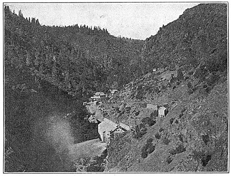
| Fig. 2. Exterior View of De Sabla River Power House |
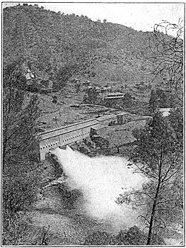
| |||
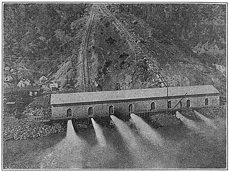
| Fig. 3. Exterior View of Colgate Power House. |
After the installation of the Colgate system the increased demand for energy resulted in a development upon Butte Creek by the Bay Counties interests. A small station at Centerville was purchased and the construction of the so-called De Salba station was begun on Butte Creek, utilizing waters of that stream and the west branch of the Feather River. The installation at Centerville consists of two 550-hp generators and one 1200-hp generator which was subsequently installed, while at De Sabla there are two 3333-hp generators, the latter being placed in service in the fall of 1903. From these plants a high-tension line is operated through Butte and Yuba Counties, connecting with the transmission line from Colgate station at Oroville, another branch operating to Chico and Colusa; thence through Gridley to Marysville and Nicolaus, where it is again tied in with the Bay Counties circuits.
AUBURN AND NEWCASTLE PLANTS.
Coincident with the construction of the De Sabla system, the Central California Electric Company built two small hydroelectric plants at Auburn and Newcastle, in Placer County, along the lower lines of the ditches of the South Yuba Water Company, to supply energy to Sacramento. This work was begun in 1895, and in 1900 a power plant was built at Alta, in Placer County. The first transmission line from Auburn and Newcastle to Sacramento was operated at 15,000 volts, later being increased to 30,000 volts, and then to 60,000 volts. The original installation at Alta consisted of three 1333-hp generators operated by Girard turbines under a head of 66o ft. At Auburn a 670-hp generator was operated under a wheel head of 206 ft., and at Newcastle two 536-hp generators were driven by impulse wheels under a head of 464 ft. The irrigation system of the South Yuba Water Company permitted the installation in 1908 of a 5500-kw plant on Deer Creek, operating under a head of 737 ft.
The hydraulic resources of the present organization are indicated by the fact that the total water storage available for power service is 1,173,768,000 cu. Ft. and for irrigation 2,362,646,550 cu. ft., or a total sufficient to supply the city of San Francisco for over two years on the basis of a daily use of 35,000,000 gal. On Jan. 1, 1911, the company had 174 miles of ditches and flumes for power service and 383.4 miles for irrigation. Twenty-five pipe lines, aggregating 65,721 ft., were in service, supplying forty-five waterwheels. At that time there were 178 substations located on transmission lines, having a total transformer capacity of 206,025 hp.
The rating of the plants on the hydroelectric system of the Pacific Gas & Electric Company, as of Oct. 1 last, is as follows: De Sabla, 13,000 kw; Colgate, 14,200 kw; Alta, 2000 kw; Newcastle, Soo kw; Electra, 20,000 kw; Centerville, 6400 kw; Yuba, 660 kw; Auburn, 500 kw; Folsom, 3750 kw ; Deer Creek, 5500 kw; total, 66,810 kw.
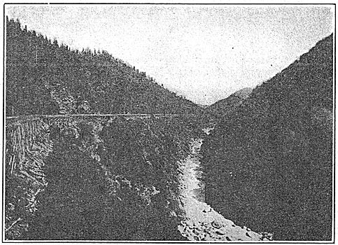
| |||
| Fig. 4. Flume for Colgate Power Station |
| |||
| Fig. 5. Exterior View of Electra Power House. |
The operation of the system is controlled from the office of a load dispatcher in Oakland. The present method of operation is the result of long experience, and it is based upon the two fundamental points that but one person should be in authority so far as the handling of the load and the regulation of voltage are concerned, and that perfect telephone service must exist between the principal power plants and the important switching stations. The Bay Counties Power Company was the nucleus of the present system, and for several years the plant at Colgate was considered the operating headquarters.
From this point were handled not only the speed and voltage regulation but also the line switching for the entire system. With the taking over of the Standard Electric Company's system and the operation of the two networks in parallel it became necessary to control the two systems from a point so far as possible common to the two. The south tower of the Carquinez span was selected as the place, and until 1907 the system was administered from this location. The new location at Oakland is within easy access of San Francisco and at the same time sufficiently removed from the larger city to facilitate the prompt and accurate handling of the system without interference.
Water cannot be taken out of a ditch or flume, a powerhouse superintendent or foreman cannot shut down a generator or change the load carried on the station, and a line crew cannot work on a line without first having the consent of the load dispatcher's office. This official is at all times in direct telephone communication with the entire system, and in the occurrence of trouble which might interrupt the service has absolute control of all matters in connection with the resumption of service. The division of load and the regulation of voltage is by no means the most important part of the dispatcher's work, for the direction of affairs in times of emergency is a task calling for unusual decision and speed of action. Trouble on any line in the great network will affect the entire system to some degree. The trouble must be located without loss of time and the affected section cut out so far as possible without interfering with the continuity of service. The different generating stations may be thrown out of synchronism, or the machines in a single plant may be thus affected. If the trouble is far enough removed from the stations, the generators will not fall out of step, and the interruption is consequently only momentary. The system of switching in use enables different power plants to be separated, leaving one or more running together upon such lines and loads as can be conveniently carried.
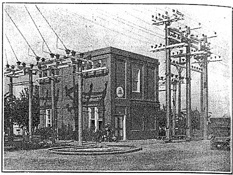
| |||
| Fig. 6. Premium Substation |
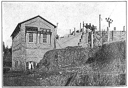
| |||
| Fig. 7. Upper Power House at Folsom. |
The load dispatcher's office contains a board 18 ft. long and 8 ft. high, upon which is a working model of the entire system. Every generating and substation, switching point, transmission line and switch controlling high-tension energy is shown, and all switches are made up in dummy form for hand setting to correspond with the conditions in the field. The particular kind of switch, whether oil or air-break, is indicated by the form of the dummy, the oil switches being circular and the air switches rectangular. The face of the board is of slate. The lines of the Great Western Power Company, which are operated at 100,000 volts, are shown in gray; foreign companies' lines are shown in dotted red; Pacific 60,000-volt lines are shown in full red; 22,000-volt to 24,000-volt lines in blue; 15,000-volt to 17,000-volt lines in green; 5,000-volt to 11,000-volt lines in yellow, and 2000-volt to 4000-volt lines in brown. Hydroelectric plants are shown in white; line symbols and auxiliary plants in yellow and white. Substations are shown in white lines and transformer banks are colored according to voltage ratings. Low-voltage single-throw and double-throw switches are also indicated. Immediately after the operation of any high-tension switch, either on a direct order from the load dispatcher's office or during trouble when the regular routine tests are made, such action is immediately reported to the dispatcher. When an order is given to operate a switch no change is made on the board until the operator to whom the order has been given reports it carried out, when the dummy switch is set accordingly. A load dispatcher coming on watch can thus tell at a glance what lines are out of service and what switches are open or closed.
| |||
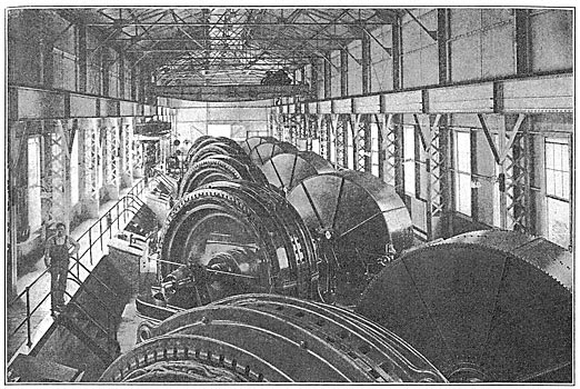
| Fig. 8. Interior View of Electra Power House |
| |||
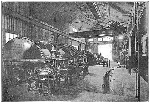
| Fig. 9. Interior View of De Sabla Power House. |
Load readings from all important generating and distributing points are telephoned to the dispatcher every twelve hours and curves are plotted daily showing the load handled at the company's own plants, steam and water, and the energy purchased, as well as the total load upon the system. This information is subdivided under maximum, average and peak loads, with the kilowatt-hour output from all generating sources, and statistics are kept relating to the available output, the flow and depth of water at all strategic points. A small mechanical indicator is used in the office to show the height of water, peak capacity on a two-hour run, present and average load at every generating plant on the hydroelectric system. The frequency is maintained between 59 and 61 cycles, and in case it passes either limit a set of corresponding tuning reeds is automatically vibrated, sounding the alarm to the dispatcher at the board. The frequency is recorded continually on a curve-drawing instrument. Besides the load conditions, the dispatcher's office keeps a record of the time and duration of all service interruptions at substations and plants, weather conditions, depth of snow and water at gaging stations, flow over dams, amount of water passing through ditches and flumes, and the causes of trouble. The latter are classified under sixteen heads, represented by a letter symbol, to facilitate the preparation of reports, and all reports are delivered daily at 8:30 a. m. from the dispatcher to the main office of the company in San Francisco. Another valuable feature of the work is the keeping of a diary of all important occurrences and the posting of dates of line switch release and other forthcoming events in a memorandum diary.
 |
TELEPHONE SERVICE.
Although telephone lines are run on all transmission poles or towers, the company also utilized the service of the commercial telephone organization at many points, notably in long-distance service. The lines carried on the company's transmission rights-of-way are mainly used in routine business, as in the reports of linemen, loads carried and the like. For communicating between important stations the company leases circuits from the telephone companies, these running on the regular toll leads, and as they are on different routes they are not affected to any extent by transmission difficulties.
The paralleling of the various stations, the two most remote being separated by nearly 400 miles of line and with widely varying loads and capacities, has given little trouble. Experience has shown that this can be done much more easily than the paralleling of generators in the same station. The phasing in of the system is done almost entirely on the high-voltage side, using small transformers between line and ground for synchronizing. The operation of all plants in parallel greatly simplifies the regulation of voltage and by enabling the capacities of the various plants to be utilized to the fullest degree results in economy of water and fuel. The station generators are connected directly to the line without automatic circuit-breaking equipment of any kind, and power is never cut entirely off the lines unless it is impossible to keep it on. Most of the lines feeding into the system are supplied from transformers delta-connected on the low-tension side and star-connected on the high tension, with grounded neutral. No hesitation is practised in opening the 60,000-volt lines under heavy short-circuits. Governing is handled at any stated plant, and the fluctuations of the load in this service range usually between 3000 kw and 5000 kw, although at times the load varies by 8000 kw or 9000 kw. No telegraph service is employed on the system. All important plants are equipped with governors which, except in the case of the governing station, are set to work sluggishly and do not operate except under a wide range of speed.
The greater number of connections to the system are made by means of three transformers connected delta on the low-tension and star on the high-tension side. While this throws a dead short on the line when a wire falls, it gives a positive indication of trouble which the company considers of the utmost value, especially in reference to safe operation in densely populated communities. Some occasional objection from telephone and telegraph companies has proved unfounded, and has been traced to a static unbalance caused by an arcing ground on the line, which would have been greater on an ungrounded system. This has been clearly shown by the experiment of shifting the load, say 3000 kw, from three to two transformers of a bank, with practically no effect on the parallel telephone line.
| |||
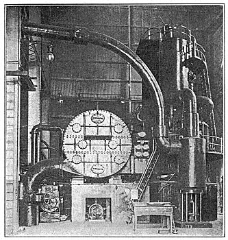
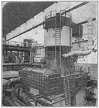
| Fig. 11. Turbo-Generator, Station C, Oakland |
| |||
| Fig. 12. 15,000-Kw Turbo-Generator Set, Station A, San Francisco. |
With both step-up and step-down transformers the company has no hesitation in making two transformers carry the normal load of three in emergencies. Where the load is small a customer is often supplied from two transformers and sometimes from only one. Special care is given to the ground connection in such cases, although only at rare occasions has the static strain on the secondary caused grounding. The company has no operating preference between the star and the delta low-voltage connection. Most of the transformers used range in size from 100 kw to 1500 kw, and are of the shell type of construction. On account of the saving in copper the company is using Y-connections on the distribution drop leads to an increasing extent. Regular tests are made on the cooling coils of transformers to ascertain their condition, the tests being along the lines of draining, siphoning water through coils, forcing air through and applying a pressure gage with one end closed. This is often done without taking the voltage off the transformer. The company's experience indicates that the best case for oil-cooled transformers is made of boiler-iron and provided with cast-iron base and top.
The company designs its own oil switches to a large degree, these being of the hand-operated type with quadruple break. In a few cases, where lines are tied together at both ends, reverse-current relays have been installed for use in connection with switch operation. Little trouble exists from lightning on the system, probably on account of the absence of thunderstorms on the middle Pacific Coast. To protect the lines against abnormal voltages, however, a considerable use is made of horn-gap arresters with the air-gaps set to arc over at 25 per cent above normal voltage. These are installed only at the generating plants and more important stations on the transmission network. Comparatively little trouble is experienced also with insulators, except in the bay district, where dirt and salt are carried in by ocean fogs. This difficulty is overcome by the expedient of wiping off the under parts of the insulators about twice a year, shutting down the line section for the moment. The exposed portions of the insulators are usually cleaned sufficiently by rain to make wiping all over unnecessary. Both suspension and upright types of insulators are in use on the system, and both wooden poles and steel towers are employed to carry the company's transmission lines.
AUXILIARY STEAM PLANTS.
In the auxiliary steam plants of the company turbine units are employed, and fuel oil is burned, under the boilers. The general practice is to permit the turbines to run light upon the bus, thus affording an immediate supply of energy in case of a threatened interruption, and also permitting the effect of inductive loads to be to a large degree offset, since the generators run practically as synchronous motors. The load factor of the entire system is about 70 per cent. At present additional steam plant capacity is being installed in the company's so-called Station C, in Oakland, and Station A, at San Francisco. In the former case a 12,000-kw vertical Curtis turbine set is being erected, the existing plant consisting of a 9000-kw unit of the same type, installed about two years ago. Four Parker and eight McNaull boilers with furnaces adapted to the burning of fuel oil will furnish steam. The steam mains are to be interconnected, and the dry-vacuum pumps will be cross-connected to both condensers. The auxiliaries of the larger unit include a Cochrane separator of the receiver type with an automatic trap close to the turbine throttle, a 2000-sq. ft. Wheeler feed-water heater, two step-bearing pumps built for operation at 1200 lb. per square inch, two guide-bearing oil pumps and a 5-in. Alberger turbine-driven boiler-feed pump. A 50-ton accumulator is also provided. Two hot-well pumps are being installed, one being motor-driven and the other turbine-operated. The new turbine will be fitted with a horizontal automatic relief valve controlled by water pressure from a remote point. Other features will be the installation of peepholes in the oil-burning furnaces at the level of the eyes, duplicate oil lines which can be blown out by steam and Owens oil burners. Laidlaw-Dunn-Gordon dry-vacuum pumps are to be used.
At the San Francisco station a 15,000-kw Curtis turbine is being installed. A 12,000-kw unit has lately been placed in service to take the place of a 1500-kw compound engine-driven set. The larger unit also supersedes another set of this size. No additional boiler capacity has been installed on account of the turbines, the plant containing two 35oo-kw units, five I500-kw units and one 500-kw engine unit as well as the two turbines. The superior economy of the turbine even compared with triple-expansion condensing engines was a controlling point in the decision to replace the engines. The use of oil as fuel in the auxiliary plants enables the service to be picked up with practically no interruption in case of trouble on the hydroelectric system, the only indication of the change being a possible slight drop in frequency in the majority of cases. This journal is particularly under obligation to Mr. John A. Britton, vice-president and general manager, to Mr. R. J. Cantrell, property agent, and to Mr. Paul M. Downing, engineer of operation and maintenance, hydroelectric section, all of the Pacific Gas & Electric Company, for information furnished by them in connection with the preparation of this article.
