[Trade Journal]
Publication: Electrical World
New York, NY, United States
vol. 59, no. 26, p. 1425-1434, col. 1-2
DEVELOPMENTS ON SPOKANE RIVER, WASH. II.
Steam-Turbine Relay Station, Switching Stations and Substations of the Washington Water Power Company.
Interconnection of the Company's Various Stations and Method of Operating System, Which
Possesses a High Load-Factor--Description of General Transmission System
Embracing Circuits of Various Voltages.
A DESCRIPTION of the newer developments of the Washington Water Power Company at Little Falls and at Long Lake was given in last week's article on the system. In the present article the steam-turbine station and the Post Street and Twenty-ninth Avenue substations will receive attention, as well as the general method of operating the system. As having a bearing on the steam-station design, it should be mentioned that slack coal at Spokane costs $4,23 a tona factor of considerable importance.
STEAM-TURBINE RELAY STATION.
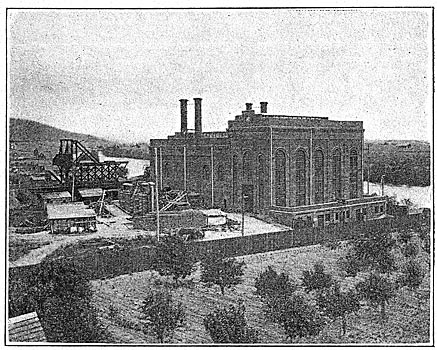
When the flow of water in the Spokane River is unduly slack it has been found advisable under the present condition of development to operate a steam station as a relay to the hydroelectric properties. To help carry the load at such times or in emergencies there has been erected, at a place called Ross Park, within the city limits and on the Spokane River, a modern steam-turbine station capable of generating some 14,000 kw. The illustrations published herewith give a fair impression of the station design, its location and layout. It has not been used, however, to any extent since its erection, all told probably not more than six months; but it has amply proved its worth.
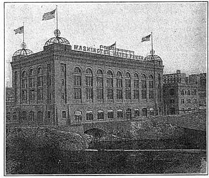
| |||
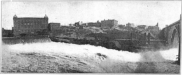
| Fig. 1 - Main Substation and Spokane Hydroelectric Station of Washington Water Power Company at Lower Falls of Spokane River in the Heart of the City. |
The building is of red brick resting upon a reinforced-concrete foundation. The walls of the turbine room rise 76 ft. 4 in. above the turbine-room floor, and the walls of the boiler room are 53 ft. 3 in. above the boiler-room floor. All trenches and well covers are made watertight so that exceptionally high water is not liable to flood the turbine room. Two large main doorways, one in the east end of the boiler room and the other in the northerly end of the turbine room, are provided for bringing in heavy material. An annex built on the western side of the turbine room contains the oil room, blower room, tool and supply room, workshop, etc. Located directly over the office is a storage-battery room, energy from which is used for operating the switchboard lamps and motor-driven switches. Abundant natural illumination is obtained throughout the entire structure.
The turbine room is equipped with a 40-ton Case traveling crane, having a span of 37.5 ft. The motors, of which there are four, the main hoist being rated at 40 hp and the auxiliary hoist at 25 hp, are of the direct-current, 110-volt series type, receiving energy from the exciter bus. Located in the northerly end of the turbine-room annex is the laboratory. There is provided the necessary apparatus for performing the simpler and common tests on oils, fuels and flue gases. The equipment comprises coal-sampling apparatus, flue-gas sampling apparatus, flue-gas analyzer, fire and flash test machines, reduction oven, Parr calorimeter, viscometer, chemical balance and weights.
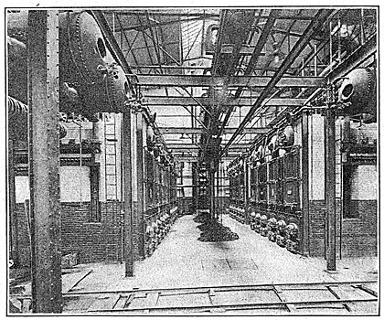
The boiler-room equipment comprises twelve water-tube boilers of the Aultman & Taylor type, set in batteries of two and rated at 500 hp each. The boilers are suspended from steel supports and are equipped with superheaters and eight of them with stationary grates. The settings are built of common red brick, firebrick-lined, and are cement capped, the steam drums being covered with cement arches for heat insulation. The four last boilers to be installed differ somewhat in arrangement from the other eight in that they are equipped with rocking instead of stationary grates and the steam drums are covered by means of vitrobestos instead of cement. The settings are also 1 ft. higher. As will be noted from Fig. 2, the boilers are arranged on either side of the room with a firing aisle in the center.
 |
| Fig. 2 - Sectional Elevation of Boiler Room, Spokane Steam Station. |
FEED-WATER SYSTEM.
The boiler feed-water system includes two Cochrane open feed-water heaters and three Epping-Carpenter feed-water pumps. The heaters receive their water supply directly from the hot-water tank into which the condensate and make-up water find their way. The heaters are inter-connected by a 4-in. equalizing pipe, and from the bottom of both there is an 8-in. water line which makes a circuit beneath the floor level and passes to the feed pump room located at the western end and beneath the boiler room. From this 8-in. line the three boiler-feed pumps take their supply. The three pumps feed a 6-in. cast-iron header built on the loop system from which 2.5-in, brass pipes branch vertically to the boiler room. The connections to the boilers are taken from these feed riser loops. Inserted in each of the connections is a combination stop and check valve which automatically closes in case there is a reversal of flow.
The arrangement of valves in the heater and feed-pump connections is such as to give the utmost flexibility and permit cleaning and repairs without disturbing the system. The feed-water heaters are rated at 3000 hp each.
COAL-HANDLING SYSTEM.
The coal-handling facilities at the station consist of a spur from the Great Northern Railroad which, crossing over scales at an elevation, branches, one branch descending and passing directly to the turbine room and the other branch ascending to the coal embankment and trestle. The cars upon the trestle may be unloaded manually or by an unloader of special design similar to that employed in unloading grain cars. If the coal is unloaded in hopper cars, they simply dump their fuel into the yard beneath the trestle.
| |||
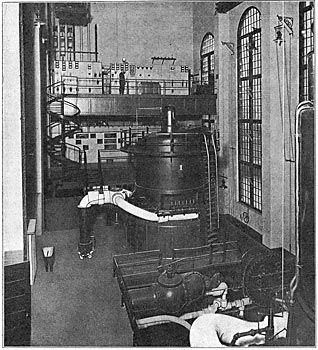
| Fig. 3 - Turbine Room, Spokane Steam Station. |
Coal is delivered to the boiler room by an Exeter Machine Company's bucket conveyor driven by a 30-hp induction motor through a triple gear reduction. The coal can be crushed if necessary by a coal cracker driven by a 30-hp induction motor. The buckets of the conveyor are loaded by a bucket loader so arranged on a track that the buckets may be filled from the coal cracker directly or from a storage hopper. Two movable bucket-tripping devices are located on the upper ingoing side of the bucket circuit, one for dumping the buckets into the storage hopper and the other for dumping the buckets into the weighing hopper. The latter is suspended from a movable truck and from it the fuel is dumped to the floor below.
ASH-HANDLING EQUIPMENT.
For the disposal of ashes there are two tunnels almost the full length of the boiler room, whose axes are directly beneath the centers of the ash pits. The latter consist of concrete hoppers protruding into the tunnels and provided at their lower ends with double clamshell gates. Running transversely with the boiler room and extending outside of the building line is a third tunnel whose southerly end comes up to the street level and whose northerly end serves temporarily for housing the boiler from which the plant is heated during the winter months when the station is not in use. 24-in. gage track embedded in the concrete floor of all three tunnels serves for the ash cars, and at the junctions of the lateral tunnels with the trunk tunnel are ball-hearing turntables. At the point to the south side at the center line of the building and coal conveyor is an elevator shaft. The ashes are drawn out of the ash pits into cars which are dumped on the low land outside the station and adjacent to the river; or the ashes can be hoisted 60 ft. to a storage bin and clumped thence into standard cars. The operating mechanism for the elevator was made up of materials left from the, construction plant and is. driven by a worm shaft connected to a 5-hp induction motor.
STACKS, FLOORS AND BREECHINGS.
Running lengthwise of the boiler room, are two steel breechings passing between the rear end of the settings and the outside walls, being connected with each 'setting by a steel thimble provided with a butterfly damper. At the central point of each breeching there is an uptake connecting it with the bower intake chamber. The blowers are of Buffalo Forge Company's build and are driven by simple piston-valve engines. The fans are of the overhung type.
 |
| Fig. 4 - Sectional Elevation of Steam-Turbine Station, Washington Water Power Station. |
Rising vertically from the wall sides of the blower casings are two steel stacks 5.5 ft. in diameter and extending 84 ft. 2 in. above the grates. Regulators are inserted in the supply line to each engine, which are in turn controlled by damper regulators in such manner that the speed of the blowers varies inversely with the variation in steam pressure. All of the surfaces of the blowers and breechings are lagged in order to keep down the temperature of the boiler room during warm weather.
HIGHPRESSURE STEAM SYSTEM.
The high-pressure steam piping includes two systems complete with traps and trap lines, namely, a superheated steam system and a saturated steam system, each of which is independent 'of the other during normal operation but so built that they can be interconnected if necessary.
The two main generating units are supplied with steam from the superheater headers, while the auxiliaries receive their supply from the saturated steam lines. The pipe joints on the superheated lines are of the Van Stone & Crane lap type and all valves and fittings are of steel. Valves 8 in. and over are of the rising-stem type with nickel steel stems and trimmings, and valves 50 in. and 12 in. in size are provided with by-pass valves.
All valves 8 in. and above in the boiler connections and the main headers, except the stop and automatic check valves, may be closed from the boiler-room floor.
The main header is divided by valves into sections corresponding to each battery, the central section of each main header comprising an expansion loop made up of four To-in. quarter bends. An 8-in. chain-operated gate valve is placed near each boiler superheater and an 8-in. stop and automatic check valve is placed in the boiler connection with the main header. An 8-in. quarter bend placed between these valves completes the boiler connection to the superheated steam header. There are two 4-in. saturated steam headers which combine into one 6-in. header in the turbine room for supplying the auxiliaries.
EXHAUST SYSTEM.
All of the various auxiliaries, including the blower engines and the feed-water pumps, exhaust into a common header leading to both heaters and also with the atmospheric exhaust from the turbines. The exhaust from one of the circulating pumps can be turned into the third stage of the turbine to which it is connected.
TURBO-GENERATORS.
The two main generating units-are of the General Electric type, one being a four-stage, 5000-kw machine running at 720 r.p.m. and directly connected to a 10-pole, 60-cycle, three-phase, 13,200-volt generator by means of a one-piece shaft guided by an upper, middle and lower bearing, and with the entire weight of the unit carried on a step bearing. The turbine is provided with an overspeed tripping device which operates when the speed becomes excessive, in which case the generator will run as a synchronous motor until normal conditions can be re-established. The upper end of the generator is provided with a hood and connection to a forced system of ventilation.
| |||
| Fig. 5 - Boiler Room, Steam-Turbine Station in Spokane. |
The second unit is a five-stage, 9000-kw machine of the same general characteristics as the other machine, but connected to the generator by means of a flexible shaft. The latter is made in two pieces, the lower piece carrying the steam turbine and having at its top a flexible-disk diaphragm coupling which is keyed to the shaft. The field structure of the generator is placed on the upper part of the shaft by means of a taper fit which will allow the field structure to slip a small amount in case of shocks produced by severe short-circuits.
To keep down the generator temperatures at heavy loads a system of ventilation has been provided and two motor-driven blowers, one rated at 30 hp and the other at 40 hp, installed. The blowers discharge into an underfloor air duct which rises up through the turbine-room floor near the intake wells. From the floor level for a distance of about 10 ft. is a rectangular sheet-iron duct provided with two connections extending to the ventilating hood of each main generator.
The energy for excitation is supplied from two exciter units, one an 85-kw motor-driven set and the other a 75-kw steam-turbine set. The latter is operated non-condensing and,is equipped with a 125-volt interpole generator running at 2400 r.p.m.
| |||
| Fig. 6 - Steam-Turbine Station, Washington Water Power Company, on Spokane River. |
CONDENSING SYSTEM.
The condensing system includes, besides the condensers for the turbo-generators, the necessary auxiliary apparatus, Both units are fitted with Worthington surface condensers. Circulating water is taken from the Spokane River by an engine-driven centrifugal pump, an intake tunnel leading from the river to a well beneath the pump. The rest of the equipment comprises a steam-driven vacuum pump and. a duplex hot-well pump discharging into the feed-water heaters. In order to shorten the time for priming the circulating pump a weight-closed check valve is attached to the submerged end of the circulating discharge pipe, which valve closes automatically with the cessation or reversal of flow. A 4-in. flooding line from the house-service system enters the circulation head of the condenser and may be brought into service in emergencies. The hot-well pump of the larger condenser is driven by means of an induction motor.
LUBRICATING SYSTEM.
The step bearings of the two main units are floated and lubricated by means of a high-pressure oiling system, comprising three high-pressure, steam-driven pumps and two 50-gal. accumulators. The low-pressure, or guide-bearing, oil system is provided with lubricant taken from the oil filters and delivered at a pressure of 125 lb. by two steam-driven pumps. From this system the guide bearings and also both governors are supplied, the latter through equalizing tanks. The high-pressure and low-pressure pumps are equipped with relief valves so that the pressure cannot rise above the predetermined limit.
The majority of the ordinary bearings on the auxiliaries are lubricated by sight-drop gravity oil cups, but all steam cylinder lubrication is by means of sight-feed force pumps All of the high-speed main bearings are equipped with a-ring oiling system. Two 750-gal. tanks and one 500-gal. tank store the oil, which may be forced into the oil filters by air pressure.
OPERATING FORCE.
When the load assumes a constant daily value and the shifts are regular, the crew necessary for the operation of the station comprises one station foreman, one operator per shift, one engineer per shift, one conveyor engineer per shift, two oilers per shift, one fireman per boiler per shift, one extra fireman per shift, two laborers per shift, one mechanic's helper per shift, three water tenders, one mechanic and a janitor. Where the loads assume a fairly constant nature with intermittent peaks of short duration, steaming conditions give best results with one boiler per 1000 kw normal load, plus one boiler with a second boiler banked but not cut in. Loads in excess of 4000 kw are carried more easily and more economically on the larger unit, which also operates with less vibration and noise under full speed.
TELEPHONE AND ALARM-BELL SYSTEMS.
Telephone connections with the main office building of the company are had over a local connection to the company's local central and another over the transmission telephone line. Both sets of telephones are located in an insulated booth on the switchboard floor. The local telephone connection has a repeating coil inserted, so that the plant office telephone or the engineer's telephone located in the turbine gallery booth can be connected with the company's local central or the three plant telephones can be used locally without disturbing the rest of the system. The transmission telephone system is connected with the system operator's office and at the steam-plant end is provided with duplicate telephones and switch-over devices, together with alarm attachments and high-tension fuses. The ringing of either telephone operates a mercury-contact telephone drop which causes a bell to ring until the drop is restored. A watchman's time detector and fire-alarm system are also in use.
COMPRESSED-AIR SYSTEM.
A direct-current 5-hp, 110-volt series, motor-driven, duplex, single-acting, portable air compressor furnishes air at a pressure of 75 lb. for forcing oil from the storage tanks to the oil filters and for maintaining air in the guide bearing tanks. Compressed air is also used for cleaning the electrical apparatus and after the spring high-water season for agitating and removing the deposit from the mouths of the intake and discharge tunnels.
SPOKANE HYDROELECTRIC STATION.
The Spokane hydroelectric station is located at Monroe Street and the river, where a head of 70 ft. is available on the lower falls. The output of the station is used chiefly in Spokane, and the station itself will eventually be displaced by a more modern plant on the upper falls, which will use the drop of both the upper and lower falls and employ probably a long tailrace tunnel after the fashion of the stations of the Niagara Falls Power Company and the Toronto Power Company at Niagara Falls. The present equipment of the station comprises 4500 kw in waterwheel-driven alternating-current apparatus, 1950 kw in 600-volt direct-current apparatus, and 2300 kw in 300-volt direct-current apparatus. In addition there are three convertible motor-generator sets aggregating in rating 2500 kw, which may be employed on either the 300-volt or the 600-volt systems.
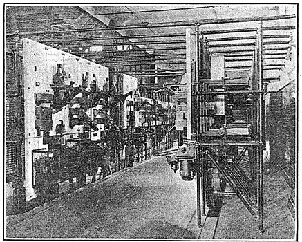
POST STREET SUBSTATION.
The chief substation of the company is located on Post Street close to the business center of Spokane, one block from the general office building of the company and near the middle of the series of rapids which extend for half a mile along the Spokane River at that point. The Post Street substation was built as a low-tension distributing and converting station for the city service in Spokane. It is most liberally designed and will suffice for the demands of the system when the load has increased to several times its present value.
| |||
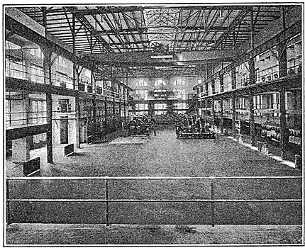
| Fig. 7 - Interior of Main Substation at Post Street, Spokane. |
The first unit was placed in operation in October, 1909, and the sixth, or last, unit installed was placed in operation last March. Alternating-current energy enters at a tension of 13,200 volts over underground feeders from the Bishop's Court substation and from the hydroelectric station in Spokane just below the substation on Post Street. The energy is then transferred or converted into energy at the following voltages: Alternating current at 4000 volts for motor service, alternating current at 2300 volts for lighting service, direct current at 600 volts for railway service, and direct current at 250-125 volts for general industrial and lighting service in the heart of the city's business district. It should be mentioned that the Bishop's Court substation merely serves as a connecting link between the overhead 13,200-volt circuits and the underground 13,200-volt circuits running from Post Street to the Twenty-ninth Avenue switching station.
| |||
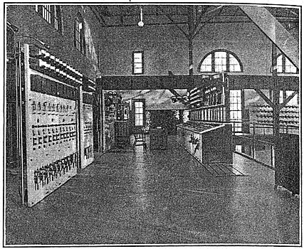
| Fig. 8 - Control Gallery at Post Substation. |
The present station equipment includes three 1500-kw and one 1000-kw motor-generator set for railway service, three 1500-kw motor-generator sets which deliver energy for the low-potential three-wire service, two exciter sets and a motor-generator booster set for charging the standby battery, two banks of single-phase and one three-phase transformer, the aggregate rating of which is 13,500 kva, for reducing the potential of the incoming circuits to 4000 volts, four-wire, three-phase. The transformers are water-cooled and are equipped with low-water and thermostatic alarms. The water may be taken from the city water mains or by gravity from the river.
Four of the units mentioned above are driven by self-starting synchronous motors and the rest by induction motors. Both the railway and the Edison generators are shunt-wound interpole machines. The former are operated in parallel with the railway machines in the hydroelectric station in Spokane, and regulation is mainly effected by the control of the latter. All incoming lines, circuits to and from the transformers, circuits to motors and all outgoing lines are controlled by remote-control, electrically operated oil Switches. These are in the immediate control of the switchboard operator and meet every demand for simple and economical operation.
| |||
| Fig. 9 - Edison Disconnection Panel at Post Substation. |
The bust structures are made up of brick walls supporting concrete slab floors. An electrically operated 33-ton crane with a span of 64 ft. travels the full length of the building. A standard-gage track connecting with the street-railway system enters the station at the end opposite from the benchboard. The dimensions of the main floor of this building are 200 ft. by 100 ft. The station is finished with a red tile floor and with green-glazed tile wainscot.
Arranged around three sides of the building are the following switch structures: At the end under the benchboard gallery, a 13,200-volt oil-switch structure; on the left facing the room from the benchboard gallery, the railway, Edison and standby battery switchboards; at the right, the main taco-volt switch structure and the current transformers with their panels for the arc-lighting system. On both sides of tile building and on a level with the benchboard are the power and lighting switching structures. It should be pointed out that ail of the lighting circuits and those intended for motor service are kept separated and independent throughout the entire system.
All control wiring is drawn in conduit and all conduit is exposed beneath the floor to facilitate change and removal. This feature is emphasized, as no station has yet been completed where demands have not been made for changes within a few years of the completion of the building. New inventions and changing operating conditions often play havoc with the original design. In the Post Street substation there is a minimum chance that any unforeseen change which has or may be made subsequent to the original design will disfigure the pleasing arrangement of the equipment.
All indicating meters are mounted either on the bench-board or on vertical panels at the back and to the right or left of the operator as he faces the benchboard. The circuits to and from the building pass through the downtown underground system, no aerial wires leaving the structure. The railway circuits are controlled by remote-control, electrically operated circuit-breakers and circuit-breaker type switches, the operating circuits being interlocked between the switch and breaker.
The standby battery consists of 130 cells of "Exide" battery, each cell containing seventy-seven plates. Sufficient end cells are provided to permit close regulation of the voltage, and these are controlled by four 14-point horizontal regulating switches. The rating of the battery for maximum emergency discharge is 19,000 amp for ten minutes. The one-hour amp capacity is 6346, the normal changing rate 990 amp, and the maximum charging rate 1318 amp.
The battery room is located in the basement of the building adjacent to 'the substation, and over it is a garage which stores the nine gasoline machines, five electric automobiles and five motor cycles of the company. Included in the electrics are one 2-ton, one 1-ton, one 1000-lb. and one 700-lb. truck. The first two are used by the line -department -and the other two by the meter department. They are giving satisfaction and are a' feature in effecting considerable economy in the operating department.
The station is lighted by ten 6.6-amp, 100-hour inclosed flaming-arc lamps supported from the roof purlins. All apparatus is of General Electric manufacture except the battery, which was furnished by the Electric Storage Battery Company.
TWENTY-NINTH AVENUE SUBSTATION.
This substation, 2 miles from the center of the city, is primarily a high-tension distributing point. Into and from this station enter or leave the following 60,000-volt lines: Two circuits (on one steel tower) to Little Falls, 28.4 miles; two circuits (separate pole lines) to Post Falls, 28 miles; two circuits (separate pole lines) to Spokane power house, 2 miles.
| |||
| Fig. 10 - Switching Station at Twenty-Ninth Avenue, Spokane. |
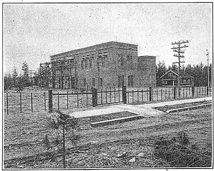
To secure a degree of selection of circuits, the station is equipped with two 60,000-volt buses, to and from which energy may be fed through either of two disconnecting switches and an oil switch.
In addition to being a switching station, there are here installed five three-phase water-cooled transformers which reduce the voltage from 60,000 to 13,200. These transformers have a capacity totalizing 13,200 kva. Power from these transformers is taken to Bishop's Court substation, located midway between Twenty-ninth Avenue substation and Post Street substation. From Bishop's Court the circuits are taken underground to Post Street substation. Each transformer may be connected to an individual bus, and all these individual buses may be interconnected, or all transformers may be connected to a common bus. The three 13,200-volt feeders are subject to a like selective arrangement. All 60,000-volt and 13,200-volt circuits are protected by aluminum-cell-type lightning arresters. A vertical instrument board provides for reading the voltage and current on all lines and for pull switches for controlling the circuits to the electrically operated, remote-control oil switches. These control circuits receive energy from a storage battery which is charged by a mercury-arc rectifier. The transformers are equipped with low-water and thermostat alarms. After leaving the transformers the cooling water is sprinkled into a cooling pond from which it is pumped to a water tower. The original water supply is obtained from a well.
The wires of all circuits in the power houses and substations are phased out and painted significant colors. This applies to control circuits as well as to power circuits.
| |||
| Fig. 11 - Exterior of Post Street Substation. |
TRANSMISSION LINES.
The Post Falls station is connected to the Spokane plants by two entirely separate 60,000-volt transmission circuits, one a direct tie line and the other having branches, one to the Coeur d'Alene mining district in Idaho and the other to the Palouse Country in southeastern Washington. The Little Falls station feeds energy into Spokane over a duplicate steel tower line, a single circuit being arranged on either side of the tower.
| |||
| Fig. 12 - Wooden Switching Tower on Coeur D'Alene 60,000-Volt Transmission Line. |
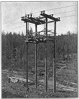
The early lines of the company were strung on wooden poles, spaced 525 ft. apart and fitted with pin insulators. The wires are spaced on a 42-in. triangle. The Coeur d'Alene line No. 1, the Post Falls tie line and Medical Lake line are thus constructed. The second line to Coeur d'Alene is composed of aluminum, spaced on an 84-in, triangle with poles 200 ft. apart. What is known as the Big Bend line, 86 miles long, is composed of aluminum strung on poles spaced 300 ft. apart and arranged on an 84-in. triangle. A spur branch to Odessa, 20 miles long, is made up of No. 7 copper-clad wire strung on wooden poles spaced 350 ft. apart and arranged on an 84-in. triangle. The load on this copper-clad circuit is not heavy, but strength was required. The Palouse line, 63 miles long, is of aluminum arranged on an 84-in, triangle on poles spaced 200 ft.
| |||
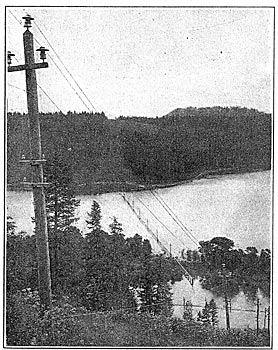
| Fig. 13 - Transmission Line No. 1 to Coeur D'Alene Mines, Crossing St. Joe River, Near Chatcolet, Idaho. |
The latest line other than the steel-tower line from Little Falls which is equipped with suspension insulators is the Pend Oreille line. This is erected on 50-ft. poles spaced 250 ft. apart, and the circuit is of No. 4 copper. The spacing of the wires is on a 7-ft. triangle, the top pin not being placed on the top of the pole, but on a small arm near the top. Along the top of the pole is a 3/8-in. steel ground wire. On all of the lines except that already noted standard porcelain pin insulators are used. The height of the poles varies according to the spans from 35 ft. for the shortest span to 50 ft. for the longest spans. The 13,200-volt lines are spaced in a 26-in. triangle on poles fitted with 9-ft. cross-arms.
SYSTEM OPERATION.
The system operator's office is located in the main office building of the company in a room adjacent to the superintendent's and assistant superintendent's offices. This location was selected so that in case of trouble the system operator might easily obtain instructions from his superior officers and thus centralize the seat of authority for the system.
The office is handled by four men, three regular operators and one relief man, who also, as part of his duties during the days he is not on relief shift, maintains the maps and records up to date. Each man is on duty nine consecutive hours per days, the morning operator's shift overlapping the afternoon shift by three hours. Located in the same room at a desk separate from the system operator's is a telephone attendant, who receives the periodical calls, regular reports and daily routine business done with the patrolmen and substation men along the high-tension transmission lines.
| |||
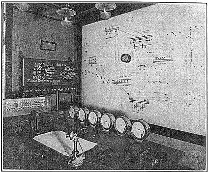
| Fig. 14 - System Operator's Room in Head Office. |
From this room direct communication can be had with all stations and substations by private telephone lines owned and operated by the company. Connections can also be made between the company's lines and the Bell Telephone Company's system, which is quite often used in cases of emergency. One interesting feature is the telegraph service to Little Falls power station over the telephone line, the one line being used simultaneously for telegraphing and telephoning.
Directly in front of the system operator's desk are six Bristol recording voltmeters, which give the alternating-current voltage of the power delivered by each generating station, the voltage of the street-railway busbars at the power house and the pressure of the three-wire Edison system at the center of distribution. These meters give a continuous record of the voltage maintained on all the separate systems and give an instant notification to the operator on shin when trouble occurs to destroy the constant potential.
Occupying the wall in front of the system operator is a large operating diagram showing all the high-tension transmission lines, tie lines, station busbars, substations and switching stations, placed there for the use of the operator in keeping record of switching conditions and operations. On this diagram the voltage of each system is represented by a certain color, as, for instance, 60,000-volt lines by green, 13,200-volt lines by red, 2300-volt lines by black, etc. Oil switches are indicated by holes in the board for push-pin tacks. When a switch is closed a pin is inserted in the hole. Oil switches are distinguished from the disconnecting and selector switches by different colored pins. The absence of a pin indicates that the switch is open, but in instances where men are to work on the line or piece of apparatus shorts and grounds are put on, and it is then represented on the diagram by red tags held to the line or apparatus by a push pin. If the line is only out of service for testing, then a green tag is substituted for the red. To protect men working on lines and apparatus further, the foreman in charge of the work to be done is required to have his name posted upon a blackboard in the system operator's office and each power station to which that line or apparatus may be connected, and under no circumstances would such a line or piece of apparatus be made alive again until cleared by the man whose name appears on the board against that line.
To the rear of the system operator is a complete set of maps of the various feeders and circuits, as, for instance, power feeders, light feeders, railway feeders, Edison underground feeders, arc circuits, etc., all kept in a convenient roller cabinet hung on the wall for ready reference. In addition to this an elaborate file of blueprints is kept at hand, giving all the detailed wiring diagrams of the stations, substations and switching stations and maps of the transmission lines. A fire-alarm recorder connected to the city's fire-alarm system gives the location of all fires in the city at first hand to the system operator.
In general, the system operator forms the head of the operating force and gives orders for the opening and closing of all switches, shifts the load according to the requirements and capacity at the various stations, controls the cutting in or out of all apparatus connected to the system, manipulates the Tainter gates, varying water levels in fact, all work with any connection whatsoever with the operation of the system is carried on through the instructions of the system operator.
Under normal operating conditions the network of circuits is divided into three separate electrical systems as follows: The Edison three-wire system, in order to be free from transmission line trouble, is carried by power generated at the Spokane power station either directly by direct-current waterwheel generators or through alternating-current generation and motor-generator transformation to direct current.
The second system is composed for the most part of transmission loadthe Coeur d'Alene mining district, Pend Oreille, Palouse, Big Bend and Long Lake transmission lines, two-thirds of the city alternating-current lighting and motor-generator loadsall of which is supplied by Post Falls station and two units of the Little Falls power station connected together by a 60,000-volt tie line.
The third system consists of the remaining load in Spokane, one-third of the city alternating-current lighting and one-half of the city railway motor-generator load.
The two latter systems occupy practically duplicate transmission lines and station buses. Each system may be tied into the other or all three together as the case may require.
The operator receives from each station one-half hourly readings of the loads and water conditions, which he posts upon the system load sheet before him. From these records and the Bristol meters on his desk, he is able to keep close watch of conditions and make changes in load generation, voltage, frequency, gate openings, etc., in order to obtain the most satisfactory and efficient operation.
The real value of a system operator looms up under abnormal or trouble conditions. When trouble affects the system it is instantly apparent on the Bristol voltmeters, and if on the high-tension lines the telephone bells sound the alarm. The system operator immediately gets into communication with the station affected and in case of transmission line trouble learns what switches have opened and then if possible gives orders to cut over to duplicate lines. The faulty line receives one or two trials, either at full voltage or by bringing the voltage up slowly on separate generators. If the short or trouble still shows up on the line ammeters, the line is cut up into sections, according to the judgment of the system operator, and tried until the faulty section is located. Patrolmen and repair men, who are on constant call, then receive directions for making the repairs. In the case of trouble on the city distribution system, as, for instance, where a feeder will not stay in owing to a short on the line, it is immediately reported and turned over to the line department, which looks after the repairing of the line. In case of trouble with the underground system, the system operator supervises the locating and disconnecting of the faulty feeder and then notifies the underground department, whose business it is to repair the trouble. In case of trouble of a serious nature, the heads of the departments affected are notified and take active charge of the situation.
The reverse side of the system load sheet is used to record all note of trouble, switching or anything which has to do with the operation of the different lines or plants. Each day a curve called the "system curve sheet" is drawn up from the one-half hourly readings taken from the "system load sheet." On the curve sheet is shown the load carried by each generating station, the Edison system load the railway load, the motor-generator load, the total. alternating-current generated and the total load, drawn in different colored inks, in order to differentiate the curves. At the top of the sheet a rubber-stamped form is filled out giving the kilowatt-hours, the maximum kw, the average kw and the load-factor for each plant and for the total load. Immediately below this form information regarding previous peaks is given, for instance on the total load, on the Edison system, on the railway system, etc.
 |
| Fig. 15 - Load Curves of the Washington Water Power Company. |
Elsewhere in the system operator's office are kept records of Coeur, d'Alene Lake elevations, flow of the river in second-feet, kilowatt-hours and maximums on the Edison system, kilowatt-hours and maximums on the railway system, kilowatt-hours and maximums on the arc system, kilowatt-hours and maximums on the total system, and various other records pertaining to the system operator's office.
A card index is kept of all cases of trouble, dates of new installations of apparatus, changes made, relay settings and all vital points of information, which by this means may be rapidly located.
Since the installation of the system operator's office in 1908, alterations and changes have been made as the exigencies demanded, until at the present time the office has become very well organized and the men well trained, which fact has accounted to a large extent for the quickness with which service is re-established after an interruption and for the uniformly good service rendered by the company.
GENERAL INFORMATION ON SYSTEM.
As a matter of general interest the curves showing the various loads on a single day and mentioned under "system operation" are reproduced. The daily load-factor of the system averages 75 per cent and has gone as high as 80 per cent. The annual load-factor for the year ended Dec. 31, 1911, was 53.7 per cent. Of special interest is the kilowatt hour output for the year ended March 31, 1912, showing for the system 139,075,021 kw-hr.
The stations of the company are operated very economically as regards labor and attendance. The Post Falls station is operated by eight men, including the foreman; the Little Falls station is also operated by eight men, and the staff at Long Lake will not be any larger. This does not mean eight men on a shift, but eight men for the entire twenty-four hours' operation.
The Washington Water Power Company's staff is as follows: President, Mr. D. L. Huntington; first vice-president, Mr. Henry M. Richards; second vice-president, Mr. H. L. Bleecker; general manager, Mr. C. S. MacCalla; superintendent of light and power, Mr. J. B. Fisken; superintendent of railways. Mr. R. A. Willson; chief draftsman, Mr. C. F. Olden; electrical engineer, Mr. V. H. Greisser; mechanical engineer, Mr. W. H. Fawcett.; superintendents of construction, Messrs. A. J. Turner and F. F. Griffin, and commercial agent, Mr. M. C. Osborn.
