[Trade Journal]
Publication: Electrical World
New York, NY, United States
vol. 59, no. 26, p. 141-146, col. 1-2
ELECTRICITY IN NORTHWEST WASHINGTON.
Generating and Distribution System of the Whatcom County Railway and Light Company of Bellingham, Wash.
Simple Hydroelectric Station at Nooksack Falls in the Forest Reserve near International Boundary. Steam Relay Station at Bellingham Burning California Fuel Oil.--Details of Development and of Oil-Burning Equipment.
THE Whatcom County Railway & Light Company, of Bellingham, Wash., supplies electric service to Bellingham, Burlington, Concrete, Glacier, Mount Vernon, Maple Falls, Lynden and Sedro-Woolley; also energy for railway service for Bellingham city lines and the 33-mile interurban railway from Bellingham to Mount Vernon and Sedro-Woolley, Wash.
| |||
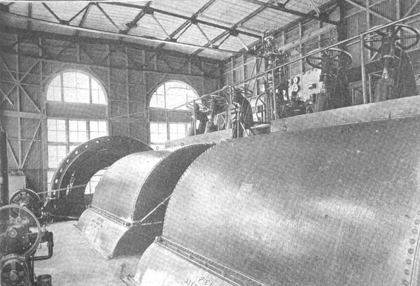
| Fig. 1--Generating Room of the Nooksack Falls Station. |
Bellingham has a population of 25,000 and is located about 18 miles south of the international boundary line of the United States and Canada and is the most northern Puget Sound city of any importance. Lynden, with a population of 1200, is 14 miles north of Bellingham. Sumas is 20 miles north, northeast of Bellingham. Nooksack Falls is 35 miles east, northeast of Bellingham. Burlington, with a population of 1300, is 24 miles south of Bellingham. Mount Vernon, whose population is 2400, is 4 miles south of Burlington. Sedro-Woolley has a population of 2100 and is five miles east of Burlington. Concrete has a population of 1200 and is 28 miles east of Burlington. Glacier, with a population of 100, and Maple Falls, with a population of 500, are 8 miles south of the international boundary line and are respectively 8 and 15 miles from Nooksack Falls. There are three sources of power for this system: Nooksack Falls development, York Street steam station and the Western Canada Power Company.
NOOKSACK FALLS DEVELOPMENT
The Nooksack Falls development is located on the right bank of the north fork of the Nooksack River in Whatcom County, Wash., and is approximately 8 miles in a south easterly direction from the town of Glacier on the Belling ham Bay & British Columbia Railway. This development is in the United States Washington Forest Reserve. The Nooksack River rises in the Cascades on the north side of Mount Baker and the flow in dry weather is principally from glaciers. The average flow of the river is about 250 second feet, and the area of the water shed is supposed to be from 100 to 110 square miles.
DAM AND HEAD WORKS
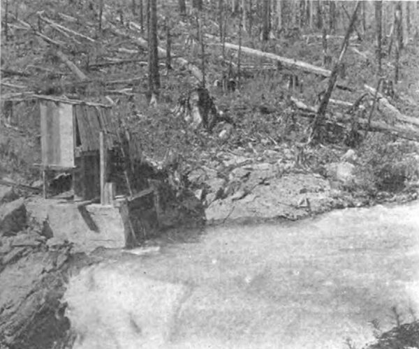
The dam is located about 80 ft. above Nooksack Falls, which has a drop of 110 ft. The dam consists of a log 4 ft. in diameter, thrown across the stream to divert the water into the intake. The ends of this log are anchored to the steep rock banks of the river by concrete piers. The upper and lower sides of the dam are sheathed and cribbed with loose rock in the center. The intake was excavated out of solid rock and consists of two concrete walls about 2 ft. thick, 18 ft. long and 16 ft. deep, holding in position a wooden frame for two 3˝ in. thick by 4 ft. wide gates, operated through a set of gears by a motor supplied with energy and controlled from the power house. At times of high water, trees, bushes and other rubbish come down the river, and in order to keep this debris from entering the system, the intake is supplied with a grid consisting of ten 56-lb. T-rails, 18 ft. long and held in place by 4-in. iron stirrups, bolted through 10 in. by 10 in. timbers across the entrance.
FOREBAY AND PENSTOCK.
Water from the intake enters the forebay through a rock tunnel, 8 ft. by 10 ft. by 260 ft. long, which is lined with 2-in. plank. The forebay is 12 ft.by 60 ft. by 22 ft. deep, is constructed of timber, 8-in. by 8-in. posts and 8-in. by 10-in. sills being used. The sides and bottom are 2.5-in. by 12-in tongued and grooved plank, spiked to the posts. The excavation for the forebay is made entirely in solid rock. Attached to the forebay is a spillway, 42 ft. long, consisting of 6-in. by 6-in. fir posts and 2.5-in. by 12-in. plank sides and bottom, by means of which the sand and other sediment is dumped directly into the Nooksack River below the Falls.
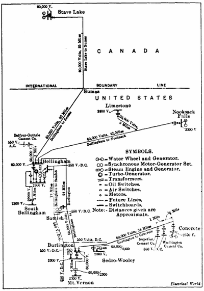 |
| Fig. 2--Diagrammatic Map of Distribution System. |
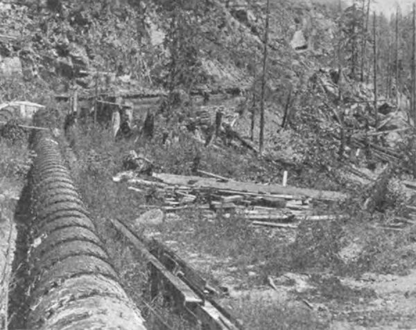
The penstock pipes consist of one 24-in. wood-stave pipe (2-in. by 6-in. stave) and %-in. iron bands with steel riveted elbows at curves, and one 47-in. diameter steel riveted pipe 0.203 in. thick. The pipes lie along a uniform grade of approximately 12 per cent, the hillside sloping transversely about 40 deg. from the horizontal. The total head from the water in the forebay to the power house is 176 ft. The capacity of the 47-in. pipe is 172 second ft. and that of the 44-in. pipe is 149 second ft., and the velocity is 16 ft. a second. The total length of each pipe line is 1380 ft., in which distance there are four tunnels of 196-ft., 28-ft., 79-ft. and 80-ft. lengths. At the lower end of the 47-in. pipe a 30-in. stand pipe, 250 ft. long and 8 in. thick, was erected, which terminated at a point above the level of the intake, so as to act as a safety valve in case of sudden closure of the valves to the water-wheel. At present, however, this stand pipe is not in use, having been found to be unnecessary. The pipe lines are anchored to the hillsides at bends and intermediate places by being imbedded in concrete blocks fastened to the rock. Because of several rock slides and consequent bursting of pipes, protecting walls have been built into the hillsides to prevent these rock slides. From the power house to the forebay a walk made of 2-in. by 12-in. plank, with railing at dangerous places, follows the pipe lines up the canyon side.
BUILDINGS.
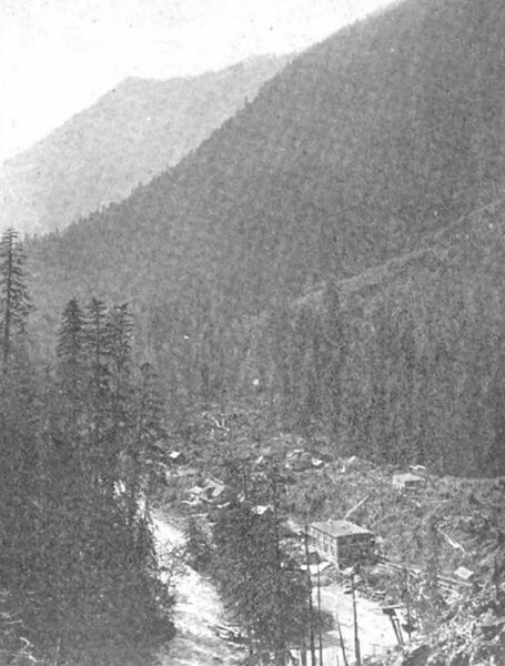
The power plant building is 40 ft. by 60 ft. by 29 ft. high, with concrete floor and three concrete walls, the fourth wall being of corrugated iron on wood frame. The roof is sup ported on a steel frame and is built of wood plank covered with tar and gravel. A tail race consisting of two concrete walls controls the spent water from the wheel.
| |||
| Fig. 3--Penstock Above Nooksack Station. |
The transformer house is located on the hillside, 150 ft. above the power house. It is 24 ft. by 22 ft. by 17 ft. high and has concrete walls and floor, and plank roof covered with tar and gravel.
The chief operator's house is a two-story frame dwelling, with woodshed attached. There are three other one-story, five-room cottages occupied by the operators. The other buildings around the plant are board sheds with the exception of the stable, which is a frame building and painted. At the town of Glacier there is a patrolman's frame dwelling and also a stable.
EQUIPMENT.
The powerplant is equipped with a six-runner, horizontal, tangential, 3200-hp, Pelton water-wheel, which runs at 200 1.p.m. A type-Q Lombard governor controls the speed of this wheel. Direct connected to the shaft of this water-wheel is a 1500-kw, Westinghouse, revolving-field, 2200-volt, three phase, 60-cycle alternator. A 45-kw, Westinghouse, 125 volt, 850-r.p.m. exciter supplies the energy for the generator field, plant lamps, motor-operating head gates and motor operating the water-wheel valves in the station. In addition to this is a motor-generator set of 14 kw rating, which supplies energy for lighting and 125-volt energy when the Nooksack station is not in operation and when energy is being transmitted from the York Street station in Bellingham. A 20-ton hand-operated traveling crane made by the Northern Engineering Works, of Detroit, Mich., is used whenever machinery is taken apart or repaired. One double Lombard oil pump with vertical tank, operated by a 5-hp motor, supplies the oil for the water-wheel governor.
| |||
| Fig. 4--Intake for the Nooksack Station. |
In the concrete transformer house are three 500-kw General Electric 2300 to 60,000-volt, oil-insulated, water-cooled transformers, with three Westinghouse single-pole, 60-cycle, 46-amp static interrupters connected on the high-tension side of the transformers.
TRANSMISSION.
From this transformer house energy is transmitted over a three-phase, 60-000-volt, single-pole line to Bellingham, a distance of 42 miles. The poles are placed 150 ft. apart and are of red cedar with an average length of 45 ft., with a minimum top diameter of 9˝ in. and a minimum bottom diameter of 15 in. Poles are braced at all curves, river and railway crossings. On the first 8 miles from the power house, through the Forest Reserve, the poles are set in rock, the remaining poles being set in hard pan and earth. The poles at river and railway crossings are 60 ft. long and at river crossings are set in log cribs, 12 ft. x 12 ft., filled with rock.
| |||
| Fig. 5--Power House and Penstock at Nooksack Falls. |
The cross-arms are of fir, with two bolts at each pin hole to prevent splitting of the arm. The arms are painted with red lead and oil and double arms are used at all brace poles and transpositions. The insulators are of Locke, 60,000 volt, high-tension porcelain, cemented to galvanized pins. They are of the four-petticoat type, with a diameter of 14 in. and a height of 12˝ in. The transmission cable throughout is a seven-strand, aluminum wire, with a conductivity nearly equal to that of No. I copper. Tie wire is No. 2 solid aluminum and about 3 ft. long at each tie. This line was designed to transmit 6000 kw at 55,000 volts. With a transmission tension of 38,000 volts the records taken from August, 1908, to August, 1911, show the transmission and transformer losses to be 10.8 per cent. line is transposed every 3 miles and terminates at the York Street station in Bellingham, Wash.
TELEPHONE LINES.
The main telephone line is strung on the poles of the high-tension line, 10 ft. below the high-tension cross-arms. Cross-arms are of fir (painted), with two galvanized iron braces to each arm, and are double at the same places as high-tension arms, as well as at transpositions, which are made at every tenth pole. The pins are of locust and the insulators are of glass. The wire is No. 10 B. & S. gauge. There are eleven 2500-ohm Stromberg-Carlson magneto telephones in use, each protected against breaks in the high-tension line by a General Electric high-tension I to I ratio telephone protective transformer with adjustable spark-gap discharge to ground.
| |||
| Fig. 6--York Street Station. |
DISTRIBUTING SYSTEM.
Around the power plant at Nooksack and along the pen stock is a small 125-volt distributing system for lighting the station and operator’s cottages, and also for operating the gates at the intake. This line consists principally of No. 6 weatherproof copper wire carried on glass insulators supported by locust pins in cross-arms bolted to wrought iron pipe posts 10 ft. long and set in the rock.
At Glacier and Maple Falls the voltage is stepped down for lighting purposes by a 10-kw transformer at Glacier and by a 25-kw transformer at Maple Falls.
A 5˝-mile transmission spur runs to Limestone, at which point there are installed three 100-kw, 60,000 to 2300-volt, oil-insulated, self-cooled transformers, controlled by a pole top disconnecting switch outside a wood frame transformer house.
Twenty-three-hundred-volt energy is taken through three No. 0 copper wires, 300 ft. to two 50-kw, 2300-volt to 440 volt pole-type transformers, located just outside the plant of the International Line Company, which has a quarry 1000 ft. up the hillside and manufactures a high grade of hydrated lime, using electric drive in the process of manufacture.
WESTERN CANADA POWER COMPANY.
The Western Canada Power Company, as the name implies, is in western Canada, 35 miles from the city of Vancouver and 18 miles north of the international boundary, line between Canada and the United States. This development will have an ultimate capacity of 100,000 hp, although at present it furnishes only one quarter of that amount. Stave Lake, which is 9 miles long with an average width of 1 mile, and 7 miles of river furnish the water at a hydro static head of 105 ft. Six 3000-kva, 4000 to 60,000 volt, step-up transformers are used for increasing the voltage for transmission purposes. A 35-mile steel-tower double line runs to Vancouver, and an 18-mile, wood pole double line runs to Sumas, which is on the boundary line. At this point the Whatcom County Railway & Light Company has contracted for the purchase of power in blocks up to 5000 kw.
YORK STREET STATION.
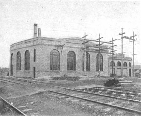
The York Street Station of the Whatcom County Railway & Light Company is located at the corner of York Street and Railroad Avenue in Bellingham. The ground on which the station is located is in the shape of an irregular "L" being bounded on the north by Whatcom Creek, on the south by York Street, on the east by the Northern Pacific Railway right-of-way and on the west by Railroad Avenue and the Bellingham Bay & British Columbia Railway.
| |||
| Fig. 7--Boiler Room, York Street Station. |
The plant acts as a relay and substation, and is made up in three sections. The boiler and engine rooms run north and south in length and are parallel to Railroad Avenue, on which is located the side track where fuel oil, wood, etc., are received at the plant. Near this side track and 120 ft. north of the boiler room is the concrete fuel oil storage tank. About 30 ft. east of the engine room is the rectangular repair shop, bordering on York Street and the Northern Pacific Railway right-of-way. About 100 ft. from the north end of the shop and 100 ft. from the northeast corner of the engine-room is the stable and carriage shed. Back of all these buildings which front on York Street is What com Creek.
BUILDINGS.
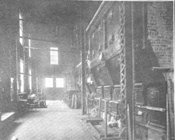
The boiler room is about 88 ft. by 45 ft. by 26 ft. high, and is made of corrugated galvanized iron on steel frame with concrete floor. The roof is nearly flat and is constructed of reinforced concrete covered with tar and gravel and supported on a steel frame. Twenty windows make the boiler room amply light by day and thirty-three 60-watt tungsten lamps with prismatic glass shades supply light at night. The construction of the building allows of expansion by moving the west wall so that four batteries of two boilers each can be installed, with a minimum amount of changes.
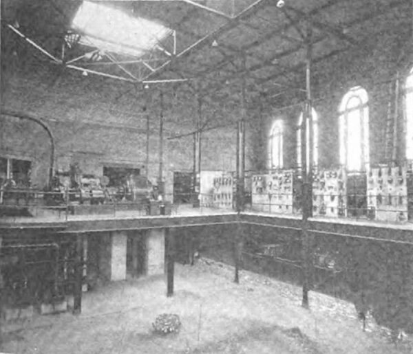
The turbine room is 83 ft. 9 in. by 87 ft. 5 in. by 75 ft. 4 in. by 65 ft. outside dimensions respectively on the north, east, south and west sides. The building has a basement 14 ft. deep and a single story of 28 ft. maximum height above ground level, making a total height from the basement floor to the top of the roof, exclusive of skylight, of 42 ft. That part of the basement which is occupied by machinery, such as feed-water and circulating pumps, has a concrete floor. The main floor of the station is of steel and reinforced concrete construction, in which is inserted conduits for electric wiring. Such wiring as cannot go in conduit in the floor is supported under the switchboard by means of steel racks. Seven large windows and a large door with windows above it supply light to the station by day and thirty-five 100-watt tungsten lamps by night.
| |||
| Fig. 8--Interior View of Turbine Room, York Street Station. |
The engine room is 100 ft. 6 in. by 38 ft. by 22 ft. to the highest part of the roof. The floor is of concrete and painted to give a better surface to keep clean and make less dust. A 17-ft. by 18-ft. basement, 12 ft. 6 in. below the main floor is furnished with a concrete floor. This basement is lighted by four 16-cp carbon lamps.
The fuel oil tank is 30 ft. by 20 ft. by 10 ft. deep and holds about 40,000 gal. of oil. It is made of 12 in concrete on sides and bottom reinforced with 2-in. round iron bars 12 in. on centers, and has a 5-in. frame concrete top rein forced with 2-in. round iron bars 6 in. on centers length ways and 12 in. on centers crossways. There are two openings in the top, which permit of filling the tank and inspection. A coil of pipe, through which exhaust steam from the pump passes, lays along the sides of this tank and keeps the oil warm and consequently thin. This oil is about as thick as thin molasses. The tank is below the level of the earth on three sides, being open to the creek on the other side.
The repair shop is about 48 ft. by 20 ft. by 14 ft. to the eaves and is of wood frame construction with shingle roof. Attached to this is a 10-ft. by 20-ft. shed used as a store room for line material and supplies. The shop is used for all repairs excepting those made on car bodies and trucks. Power is furnished to the machinery by two 220-volt motors.
FUEL.
York Street station operates as a substation most of the time, but occasionally has to act as a generating station when the power fails from other sources. At these times standard California fuel oil obtained from "Baker" "Colinga" and "Sunset" oil fields is used. This oil has a higher flash point than crude oil, because it has had all the volatile ingredients removed. The oil is pumped from the fuel tank outside by two Wagner duplex pumps and is forced at 120 lb. pressure through a heater inside the boiler room consisting of return coils of steam and oil pipes incased in a 12-in. cast-iron pipe covered with steam covering. The pumps are conveniently located about 15 ft. in front of the boilers. From this heater the oil goes to the boilers where it is burned, after being sprayed through home-made nozzles. The nozzles consist of 3/8-in. pipe with controlling valves from 1/2-in. supply mains leading into a 1-in. pipe used as a mixing chamber and containing a 1-in. wood auger bit to aid in the complete breaking up of the oil. On the end of this 1-in. pipe is a 1/2-in. by 1-in. reducing elbow, plugged on the 1/2-in. end and turned up with a horizontal slot 1˝ in. by 3/32 in. in the elbow, made with two hack-saw blades in a frame together. On the two middle of the four burners this slot is sawed in the middle of the front of the elbow, but on each of the end burners the slot is sawed to one side so that the flame will not impinge against the side walls. A nozzle is thrust through each of the four lower doors of the boiler so that they extend just inside the front wall. The grate is covered with a layer of firebrick with the exception of a space 18 in. by 15 in., through which the hot-air supply is fed directly under each burner. The air is led from the front of the boiler through tile to the back of the grate where it is heated in returning to the open hole at the front of the grate. The firebrick covering of the grate is made in the form of a spiral curve, beginning 6 in. below the nozzle of the burner and curving up as it goes towards the back of the boiler and tubes, so that when the flame leaves the fire brick cover it is directed up through the tubes, rather than directly against the bottom of these. The flame from the burners spreads out like a fan and fills nearly the whole combustion chamber.
BOILERS AND AUXILIARIES.
The steam generating units consist of a battery of two 500-hp Stirling water-tube boilers and one single 500-hp Stirling water-tube boiler, supported on reinforced concrete foundations. If more boiler capacity is needed it is planned to add another 500 hp unit to the single one making a battery of two, and if further enlargement is necessary four more boilers can be placed facing these, as has been mentioned. A stack 69 ft. 9 in. high above the tops of the boilers and 7 ft. in diameter of 3/16 in. average plate thick ness furnishes the necessary draft for the battery of two boilers, while the single boiler is equipped with a shorter stack 5 ft. in diameter.
| |||
| Fig. 9--Rear of Switchboard, York Street Station. |
The boilers are supplied with two No. 4 Spencer damper regulators. Attached to these regulators are rods operating valves which control the amount of steam and oil supplied to the fuel lines on the fronts of the boilers, so that the fires are automatically regulated for a constant pressure of 150 lb. of steam.
Feed water is supplied from the creek in the rear of the station through a Wainwright even-flow water heater by two Warren duplex pumps set in cast-iron drip pans on heavy foundations. Feed-water heater and pumps are located in the basement of the turbine room.
PIPING.
Steam piping is of the latest pattern and capable of standing 250 lb. pressure, although the pressure carried is only asbestos and canvas. about 150 lb. All supply pipes are completely covered with asbestos and canvas.
TURBINE AND EXCITER.
On the ground floor of the turbine room in the northeast part is located the turbo-alternator. This machine is a unit consisting of a four-stage, Curtis, horizontal type, 150-lb., 2000-kw, 1800-r.p.m. turbine, run condensing, and a direct connected General Electric 2000-kw, 2300-volt, 60-cycle alternator.
The turbine exciter is a separate Curtis turbine-driven, non-condensing unit running at 3600 r.p.m. The generator is rated at 35 kw and 125 volts. ENGINE. The only steam engine in the plant is a Hamilton-Corliss 1000 hp cross-compound unit, running at 150 r.p.m., made by the Hooven, Owens, Rentschler Company, of Hamilton, Ohio. This engine runs either condensing or non-condensing, and connected to it by a four-ply leather belt 75 ft. long and 6 ft. wide is a pulley which can be connected by means of a clutch to a 500-kw motor-generator set.
CONDENSERS AND PUMPS.
The turbine condenser is a 57-in., Helander patent, cast iron, barometric condenser, mounted in the rear of the turbine room outside the station. The hot well is a cylindrical tank 8 ft. by 8 ft. by 3 in. in diameter with a 4-ft. by I-ft. outlet discharging into a flume. In conjunction with this condenser is a dry vacuum pump located in the north east corner of the turbine room, a circulating pump and a 12-in. volute pump located in the basement. All three of these pumps were furnished by the Alberger Condenser Company. The engine condenser equipment is somewhat similar to that on the turbine.
The flume which carries off the hot water discharged from the condensers is made of 2-in. plank, 200 ft. long, 2 ft. 6 in. deep and 4 ft. high. Cooling water for the condensers and machines and feed water for the boilers is taken from the creek when it is not too dirty. In times of high water the creek is unusually dirty, and then water from the city mains is used from an 8-in. supply pipe. All water from the creek is taken from an intake made of 6-in. by 12-in. plank, 10 ft. by 13 ft. by 15 in. deep. Down the front is an opening 8 ft. 10˝ in. wide covered with a grid of 4-in. by 3-in. bars with 4-in. spaces. This grid keeps large foreign matter from the system, which is further protected by two iron plates 3 ft. back of this grid. These plates are 5 ft. 9 in. by 5 ft. and have 8200 8-in. holes drilled in them on 34-in. centers. The plates slide in grooves which allow of their being raised and cleaned.
MOTOR GENERATORS.
Two motor-generator sets are located near the transformer cells in the south end of the engine room. These are 500-kw General Electric machines, the generators being wound for 600-volt direct-current and the synchronous motors for 2300 volts, 60 cycles. These machines supply direct current to the 23 miles of city railway lines and part of that used by the 33-mile interurban line running between Bellingham and Mount Vernon and Sedro-Woolley. One motor generator can be connected by a clutch to the 1000-hp Corliss engine and both units run as generators, but this is very seldom done.
TRANSFORMERS.
In the three cells at the south end of the engine room are three 500-kw, 60-000 to 2300-volt, General Electric, oil-insulated, water-cooled, 60-cycle transformers. On two of the secondary windings of these transformers are connected booster transformers of 50 kw capacity for the adjustment of the voltage received at the York Street station.
SWITCHBOARD AND RACKS.
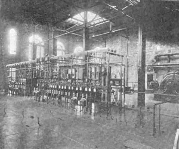
The switchboard and racks are in the southern part of the turbine room and extend nearly across the south end. Directly back of the panels is an open space through the floor about 8 in. wide, through which the heavy cables pass to angle iron racks in the basement where they are supported on heavy glass insulators and lead to the various units. About 4 ft. 6 in. in the rear (south) of the panels is an angle iron rack running the length of the switchboard and 4 ft. by 8 ft. 6 in. high. This rack supports the hand operated oil switches, instrument transformers and single. Bus line, room for another busbar line being provided. All 2300-volt apparatus is located on the angle-iron racks. The bus line is divided in the middle so that one end is a generating bus and the other is the distributing bus. Two series transformers join these two sections and through these the total energy distributed from the station is measured.
All circuit breakers and main panel switches on the board are connected with a bell alarm system, which closes the circuit and rings electric gongs whenever a switch goes out.
DISTRIBUTION SYSTEM.
Primary distribution is done at 2200 volts, and the poles have an average height of 40 ft. with a top diameter of 8 in. Primary and arc insulators are of porcelain while the secondary insulators are of glass. This aids the linemen in their work, as each wire is immediately identified by the insulator and position on the arm.
The north side of the city is supplied from York Street and is divided into four districts: Three single-phase light districts for residences and one three-phase light district for the business section. No. o feeders are run from the panels in the station to the electrical centers of the lighting districts. A future installation will include feeder voltage regulators so that a constant voltage can be kept at the centers of these lighting districts. Three-phase mains are carried about the city so that there are only a few motors on the lighting mains, and these motors are of small size. No. 4 and 6 wire is used for primary distribution from the feeder ends.
Multiple arc lighting is done at 104 volts, 20 to I ratio transformers of 1.5 to 25 kw rating being used. All transformers are provided with suitably fused cut-outs and grounded on one side of the secondary. In the residential sections, secondary circuits are made, having one transformer usually, with No. 4 or No. 6 secondary wire running not more than 1000 ft. from the transformer in any direction. If the section is very thickly settled and the load is heavy, sometimes two transformers are connected in multiple on the same circuit. In residential districts transformers are given connected loads up to three times their rated capacity and are fused for 66 per cent overload. In outlying sections of two districts transformers have been installed to boost the voltage for better service. In business districts transformers are given a connected load of one and a half times their rated capacity and fused for 45 per cent overload. Transformers feeding motor circuits are given a connected load 25 per cent greater than their rated capacity and fused for 100 per cent overload.
SOUTH BELLINGHAM SUBSTATION.
On Elk Street, in the northeast part of the Gas Works property is located the south side substation. It is 16 ft. by 16 ft. by 12 ft. high inside dimensions with an addition 16 ft. by 7 ft. by 5 ft. on top, where the high voltage wires enter through 36-in. sewer pipes. The walls are of brick, the floor is concrete and the roof is wood covered with tar paper and tar and gravel. Power is brought at 23,000 volts from York Street station through three 100-kw Stanley, oil insulated, water-cooled, 2300 to 23,000-volt transformers by three No. 4 copper wires 5 ft. apart on 60 ft. poles.
The substation equipment consists of three 100-kw Stan ley, oil-insulated, water-cooled, 23,000 to 2300-volt trans formers and a wood frame switchboard, supporting four oil switches mounted on the back of the board, three am meters, one voltmeter, three series transformers, two shunt transformers, a watt-hour meter showing the energy distributed by the station and a 100-amp Wright maximum demand meter showing the maximum load. No attendant is kept at this station, but every other day the meters are read and the transformers are inspected.
The primary and secondary distribution are similar to that of the north side from York Street station, excepting that the single-phase light districts do not each have a separate switch. Arc lighting is done by a multiple system having one primary wire controlled by a switch in the station and run in conjunction with one light wire. Separate transformers of small capacity have been installed where necessary and have from one to four arc lamps connected to them. The controlling switch is operated by one of the gas makers when the arcs are connected or disconnected. The transformers, etc., are similar to those on the north side, excepting that the secondary voltage is 115 volts on account of the longer circuits necessary in the sparsely settled districts.
The Whatcom County Railway & Light Company is operated by the Stone & Webster Management Association. Mr. L. R. Coffin is the local manager at Bellingham.

