[Trade Journal]
Publication: Electrical World
New York, NY, United States
vol. 60, no. 5, p. 241-245, col. 1-2
CANADIAN HYDROELECTRIC DEVELOPMENTS
Low-Head Generating Station of the Canadian Light & Power Company on the Beauharnois Canal at St. Timothee, Quebec.
Energy Transmitted 27 Miles at 44,000 Volts Over Steel Tower Line to Montreal Terminal Station and Auxiliary Steam-Turbine Plant on the Lachine Canal at Montreal.
SKIRTING the south side of the St. Lawrence River for a distance of about 11 miles, connecting Lakes St. Louis and St. Francis and forming a navigable high way around the Coteau and Cedar Rapids, is the Beauharnois Canal. Since the opening of the Soulanges Canal on the opposite bank of the St. Lawrence River in 1900, the Beauharnois Canal has been practically abandoned for navigation purposes. The Canadian Light & Power Company has leased the power rights from the Dominion government and has erected a station at St. Timothée, a village facing the Coteau Rapids of the St. Lawrence and about 27 miles west of Montreal.
FOREBAY.
The canal at this point is about 2000 ft. from the river, and in order to avoid long penstocks the company threw up two 2000-ft. earth embankments, 700 ft. apart and 40 ft. high, thus forming a forebay from the canal to the banks of the river. On the river side of the forebay a head-wall was erected in conjunction with the power house and spill way, the latter being arranged to pass drift-wood and ice into the St. Lawrence River. The head-wall, which is built of concrete, is 430 ft. long, 50 ft. high and 82 ft. wide at the base. A 32-ft. spillway is provided at one end, and the dam itself is composed of a series of twenty-two bays, each main penstock being connected directly with two bays. Stop-log grooves are provided on the upstream side of the racks in addition to timber flap gates across each half opening to the penstock. These gates differ somewhat from the ordinary in that they are hinged at the bottom and are provided with concrete counter-weights at the top to keep them open under normal conditions. Provision is made for removing ice formations from the penstock bays and passing the ice along the head-wall to the spillway. The flow of water is sufficient to prevent the formation of anchor ice in the tailrace, and no difficulty is experienced from ice in the river piling up and reducing the head, since Cedar Rapids is just below the tailrace and the flow of the St. Lawrence River at that point is very strong.
| |||
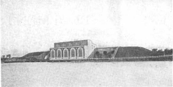
| Fig. 1--Station of Canadian Light & Power Company From River. |
HEADWORKS.
In order to provide sufficient water for the development it was necessary to enlarge the canal and to erect suitable headworks at its intake from Lake St. Francis, which is about 6 miles from the power-house site. A boat gate was installed to take the place of the former guard lock, and in addition four huge steel Tainter gates were erected to control the flow from the lake at Valleyfield. The work of enlarging the canal and constructing the intake and con trolling works was begun in the spring of 1910, and the forebay, intake, etc., were completed for the full development of 75,000 hp, although 22,950 hp is all that will be utilized at present. The generating station was placed in operation last fall.
POWER HOUSE.
The power house, which adjoins the head-wall, is only partially completed, provision being made for four units. There are false walls at either end so that the station may be extended both ways when desired. Water passes from the head-wall through steel penstocks 14 ft. in diameter, each connecting the penstock bays in a horizontal line with the wheel chambers, the distance from the intakes to the center of the surge tank being 64 ft. and the penstocks flaring out to the diameter of the tank as shown. Here again the construction is somewhat out of the ordinary in that surge tanks within the station contain the main units. These tanks, which are 27 ft. in diameter and 59 ft. high, are made of riveted steel plates and are open at the top. From the center of the wheel shaft to the top of the tank is 49 ft. In each tank are placed two 72-in. turbines on a single shaft. The machines were built by the S. Morgan Smith Company, of York, Pa., and each pair develops 7500 hp when operating under a 50-ft. head at a speed of 150 r.p.m. The entire weight of the turbines and of the water load is carried on two bearings located outside the tank, where they are readily accessible for inspection and repair. The turbine gates are regulated by Lombard governors, capable of effecting complete closure within three seconds if necessary. The draft tubes leading from the wheels to the tailrace are of concrete.
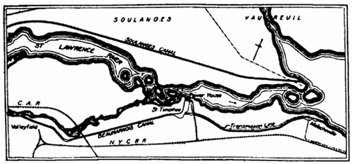 |
| Fig. 2--Map Showing Location of Power House. |
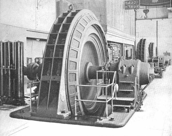
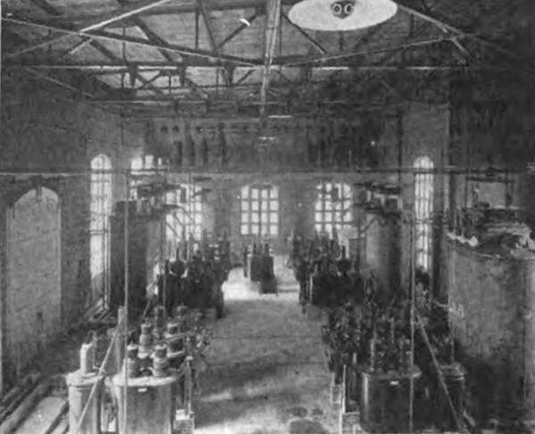
GENERATING EQUIPMENT.
The present generating equipment consists of three 5000 kva Allis-Chalmers-Bullock three-phase generators, wound for 2300 volts, 60 cycles, and operating at a speed of 150 r.p.m. There is nothing special about the design of the machines except the construction of the rotor. The latter consists of a cast-steel spider, to which is dovetailed a rim composed of thin sheet-steel laminations. The laminations are arranged in such a way that there is a joint only at every sixth sheet. The rim was built up and bolted together by loose-fitting bolts, which were later removed one at a time to permit the reaming of the holes for tightly fitting bolts. Laminated pole pieces are dovetailed to the rim, the latter being designed to take all of the stress due to centrifugal force, while the cast-steel spider simply serves to center the rim. The rotor is designed to withstand an over speed test 100 per cent above the normal. It might be mentioned in this connection that all of the electrical apparatus in the St. Timothée station was built by the Allis-Chalmers Bullock Company, Limited, in Montreal, and designed by Mr. B. T. McCormick.
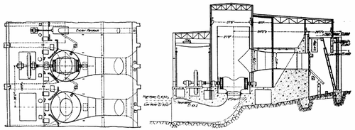 |
| Fig. 3--Plan and Cross-Section of Generating Station. |
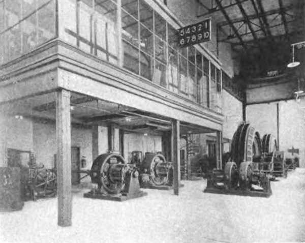
The exciter plant consists of two waterwheel-driven machines, rated at 200 kw each, in addition to a 60-kw booster set, which is designed to operate in series with the exciters and with a 100-cell storage battery in such a way that all excitation normally flows through the booster, which acts as a regulator. Thus, if a circuit-breaker on an exciter opens for any reason the battery will furnish excitation energy, since it is still connected with the circuit, being in parallel with the exciter unit. If the booster stops for any reason an automatic circuit-breaker opens and the battery supplies the excitation energy directly. The booster consists of a 60-kw, 60-volt direct-current generator, driven by a 100-hp, 220-volt, 850-r.p.m. motor. The generator is designed to operate on all voltages from zero to maximum with current flowing in the armature in either direction, and is provided with a special reversing shunt field rheostat. A shaft oscillator and an automatic overspeed device which trips the circuit-breaker in the motor circuit in case of excessive speeds are also installed. There is a common negative exciter bus in the basement of the generating room, and two positive buses are provided with a difference of potential of 30 volts maintained between them.
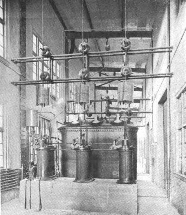
TRANSFORMERS.
Three transformers, rated at 5000 kva, three-phase, 60-cycle, step up the potential from 2300 to 48,000 volts. The transformers are oil-insulated and water-cooled and are connected in delta on both the high and the low-tension sides. Taps permit tensions of 42,000, 44,000 and 46,000 volts to be obtained. The construction of transformers is such that they may be lifted out of the cases by means of an eye-bolt in the cover, and each is provided with an emergency oil drain leading to the tailrace. The trans formers are protected against short-circuits within themselves by means of series instrument transformers in the high-tension and low-tension windings connected in opposition and operating in conjunction with an overload relay, which trips if the current in the transformer is unbalanced, and thus switches the transformer out of circuit.
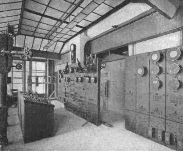
CONTROL.
The control board is located in a glass-inclosed switch board gallery overlooking the generating room. The equipment comprises direct-current exciter and battery panels, relay panels and a bench-board control desk, with a mimic diagram of the main circuit from the generators to the outgoing lines. Above the benchboard, facing the operator, is an instrument rack bearing the regulation meters and a pyrometer connected to a resistance coil in a slot of the generator by means of which the temperature of the machine may be ascertained. The overload capacity of a generator being limited by the temperature of the windings, it is possible with this connection available to watch the pyrometer instead of the wattmeter to determine if the machine is overloaded or not.
| |||
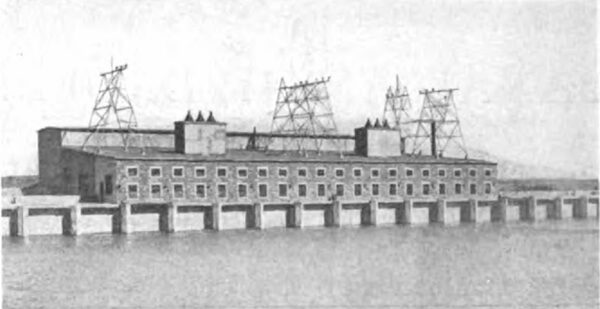
| Fig. 4--View of Station at St. TimothéE From Forebay. |
A transfer bus inclosed in a brick compartment is carried in the penstock room the full length of the station. Underneath this transfer bus is a set of auxiliary buses for each unit, and a tie bus in the center of the system connects the auxiliary with the common bus. The disconnecting switches are all provided with locking attachments. A manually operated signal snap switch indicates, by means of a bull's-eye lamp, when these switches are open or closed. The relay board in the switchboard gallery is fitted with testing jacks, so that by simple plugging in any tests may be made without interruption on meters, relays, instrument transformers, etc., while the plant is in operation. The field rheostat and the field switches are electrically operated from the benchboard. The switch equipment is of Westinghouse manufacture.
| |||
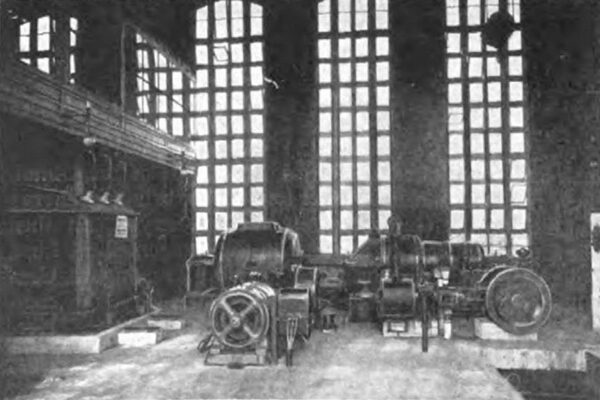
| Fig. 5--Generating Station of Canadian Light & Power Company at St. TimothéE. |
In operating the station use is made of signal pedestals near each machine, a smaller panel for each unit being provided also at the benchboard in the gallery above. On one side of the pedestal are tablets bearing the following legends: "O. K." "Full speed," "Start," "Stand by, "Shift load" and "Shut down," opposite each of which is 999 a bull's-eye lamp. Extending from the switchboard gallery is a common signal set, flashing numbers one to ten and at the same time sounding an electric automobile horn. This set is controlled from the middle panel of the benchboard and indicates to the operator on the floor which unit he is to stand by. The bull's-eye lamps opposite the tablets are lighted from the switchboard gallery, indicating to the operator what action to take, and push-button switches are provided opposite each bull's eye so that the machine operator may indicate to the switchboard operator by means of the lamp in the indicator on the benchboard that the particular order has been carried out.
TRANSMISSION LINE.
A steel tower transmission line runs from the power house to the terminal station in Montreal over a private right-of-way to the Beauharnois Canal, the north bank of which is followed as far as Melocheville, where the line turns and parallels the New York Central Railroad as far as the Canadian Pacific bridge across the St. Lawrence River. The river is crossed in two long spans and the line continues to the Lachine Canal at Rockfield, thence following the north bank of the canal to Côte St. Paul, where the terminal station is located.
| |||
| Fig. 6--Switchboard Room. |
| |||
| Fig. 7--High-Tension Transformers in Main Station. |
| |||
| Fig. 8--Exciter Units and Booster. |
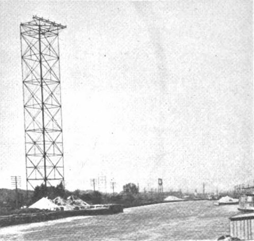
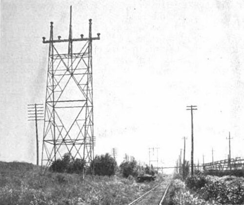
The distance between the power station and the terminal station in Montreal is approximately 26 miles, and with the exception of crossings 52-ft. towers spaced 500 ft. apart are used to support the conductors. The towers carry a duplicate three-phase circuit of No. 2-0 stranded copper, a telephone circuit and an overhead ground wire. Locke pin-type porcelain insulators are used on the main circuits, which are designed to transmit 20,000 kw at a tension of 48,000 volts. In crossing the St. Lawrence special construction had to be employed owing to the fact that the river is a navigable stream. Where the line crosses, the river is 3400 ft. wide and about 30 ft. deep. Two steel towers, 130 ft. high, were erected on the banks of the river, and a steel tower 150 ft. high was built on two concrete piers extending 15 ft. above water and erected near the center of the river about 700 ft. below the Canadian Pacific Railroad bridge.
| |||
| Fig. 9--Tower at Canal Crossing. |
Copper-clad steel cables 5/8 in. in diameter were employed for the main circuits, and 13/16-in. copper-clad cables were used for the telephone circuit. The length of spans is approximately 1750 ft. and 1735 ft. on either side of the river tower. The cables are made up of thirty-seven copper-clad wires and have a breaking strength of 20,000 lb. per square inch and a conductivity about 30 per cent that of copper cable of the same cross-section. The telephone circuit has higher tensile strength but the same ratio of conductivity as compared with copper.
| |||
| Fig. 10--View of Transmission Line. |
| |||
| Fig. 11--Terminal Station at Montreal. |
Special pains were taken to obtain a telephone system which would be reliable under the severe climatic conditions encountered and also under the conditions of operation. In the terminal telephone station the line enters through two 5-amp, 6600-volt fuses and cut-outs. The telephone equipment consists of a special telephone set having all metal parts arranged to be grounded, insulating transformer, extension bell, drainage coils, etc. Condensers are inserted in the telephone circuit to prevent the direct current from the telegraph equipment passing through the tele phone apparatus. The condensers are provided with double pole, double-throw knife switches so that if they are damaged they can readily be cut out and the line kept. closed. Both condensers must be either cut in or cut out in order to keep the telephone line balanced and prevent noise. With the condensers cut out it is possible to tele graph using only one wire of the line, as explained later. A low-voltage protector is connected to the instrument side of the insulating transformer to discharge any static caused by disturbance on the line side. The knife switch connecting the telephone to the line must be left open when the set is not in use, so that the exciting current taken by the insulating transformer will not weaken the bell signals on the line. It is necessary that the extension bell and condensers be mounted on the same type of insulators as are used for the line to prevent their becoming grounded.
| |||
| Fig. 12--Step-Down Transformers and Circuit-Breakers. |
| |||
| Fig. 13--Steam Turbo-Generator Set in Montreal Substation. |
The telegraph equipment consists of a retardation coil, line relay, key, line battery, sounder, local battery, etc. The telegraph instruments are connected between the neutral of the retardation coil and the ground, so that the telegraph current will in normal operation divide and flow in equal amounts over each of the two line wires. Under these conditions there will be no interference with the telephone circuit. If one of the line wires is broken or grounded it can be cut out by means of switches provided and communication carried on over the remaining wire. If condensers were not provided in the telephone circuit, a ground on one line wire would ground the other also through the bells, insulating transformers and drainage coils. A switch is provided in the neutral connection of the retardation coil so that if the relay is damaged it can be cut out without affecting the telegraph circuit between the other stations.
All the wires for a station are installed on porcelain insulators and insulated for 6600 volts, except those portions connected directly with the ground. No twisted pair is used for wiring and none of the wire is installed in conduit. The knife switches are mounted on insulating supports, and the telegraph equipment is arranged so that the operator is insulated when using it. This precaution is taken because of the high voltages which may be present.
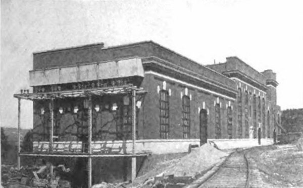
TERMINAL STATION.
The terminal station in Montreal is a fireproof structure, 50 ft. wide by 250 ft. long, housing the step-down transformer equipment and an auxiliary steam plant. The lines enter the station through oil switches and the high-tension buses are continued the length of the terminal station proper. Horn-gaps outside the station, operating in con junction with electrolytic arrester on a gallery inside the wall, protect the station equipment against surges and lightning troubles. Oil-insulated, water-cooled three-phase transformers of General Electric make, rated at 400 kva, step down the potential to 13,000 volts for local distribution, and at present four units are installed with space to spare for two more.
The switchboard equipment and switches follow standard General Electric practice. A feature of the switching arrangement is that a signal device is used on all high-tension switches to indicate the condition of the circuits by a bright or a dim light. This system is also applied to all bus bar disconnecting and feeder switches, so that in addition to the ordinary red and green lights the operator has an independent lamp indication of disconnecting switches open or closed. This device consists of an auxiliary switch connected by a stick from the disconnecting switch to the main switch. By this means disconnecting switches are not opened under load.
STEAM EQUIPMENT.
In the auxiliary steam station which occupies the other end of the terminal station there is at present installed a single 2300-volt, 1500-kw, three-phase, 60-cycle Allis Chalmers turbine set, the energy from which is stepped up in a single three-phase transformer to 13,200 volts. Excitation for this set is supplied by a 75-kw Curtis turbine exciter set or a 75-kw motor-generator set or two 60-cell Gould batteries. Steam is generated in three 333-hp Bab cock & Wilcox marine-type water-tube boilers fitted with chain-grate stokers for burning slack, or the furnace can be fed with fuel oil. The boilers are guaranteed to raise steam in twenty minutes. The coal is dumped from cars into a coal pocket below the track and conveyed thence by a Jeffrey conveyor to an overhead bunker holding 200 tons. From the bunker the coal passes through chutes to the hoppers of the stokers. The turbine is fitted with a counter current jet condenser using canal or city water. Space is provided for another boiler and another 1500-kw turbine.
