[Trade Journal]
Publication: Electrical World
New York, NY, United States
vol. 60, no. 8, p. 395-400, col. 1-2
PENNSYLVANIA WATER & POWER COMPANY
Hydroelectric Generating Station on the Susquehanna River and Terminal Station at Baltimore, Md.
Steel-Tower Transmission Lines for 70,000-Volt Circuits Equipped with Suspension-Type Insulators Features of Development Near McCall Ferry-Transmitted Energy Used for Railway, Lighting and Industrial Service in Baltimore.
THE hydroelectric development of the Pennsylvania Water & Power Company is located on the Susquehanna River at Holtwood, Pa., about 10 miles northwest of the boundary line between Pennsylvania and Maryland and 40 miles from Baltimore. There are steep banks on either side of the river at McCall Ferry with an island in midstream, and a narrow gorge between the eastern bank and a chain of islands forms a natural tail race. A fall in the river, due to a series of rapids above the site, makes available for hydraulic purposes a total head of about 63 ft.
| |||
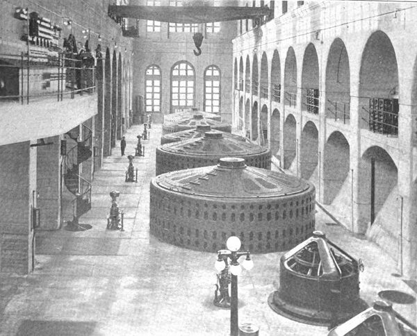
| Fig. 1--Generating Equipment of the Pennsylvania Water & Power Company at Holtwood, Pa. |
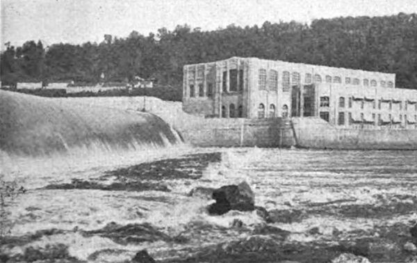
The Susquehanna River is subject to extremely high fluctuations, the floods coming with remarkable suddenness and the maximum flood discharge being roughly 225 times the minimum stream flow. For that reason a dam has been built with a spillway section for its entire length of 2350 ft. The completed plant is laid out with the idea of having its operation unaffected by flood and ice conditions more severe than any that have even been experienced on the Susquehanna. Just above the plant there is a bend in the river which causes the ice to be carried almost entirely through the channel on the western side, the normal flow of the river being westward.
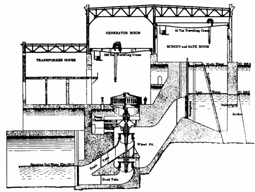 |
| Fig. 2--Sectional Elevation of Generating Station. |
DAM AND FOREBAY.
The dam across the river is built of solid concrete with an average height of 55 ft. and a width at the base of 65 ft. The downstream face is provided with the usual curve, and to allow for expansion and contraction layers of compressible material are introduced at intervals of 40 ft. The dam impounds a body of water forming a lake above it about 8 miles in length, and in order to protect itself against claims for flooding property along the river, the company acquired large tracts of land on both sides of the Susquehanna adjoining the lake thus formed. In addition a wing dam having three submerged arches, through which the water enters the forebay, is built at right angles to the main dam, between which and a rock fill extending out for approximately 300 ft. at right angles to the shore floating booms are provided so as to divert such ice and debris as are carried to the east over the spillway. The submerged arches start at the junction of the power house and the dam and extend upstream about 220 ft. The crowns of the arches are 2 ft. below low-water level, so that they are always submerged. The gap between the end of the arch construction and the rock embankment is closed by the log booms above mentioned, guided by concrete piers. Any ice which enters the forebay despite these safeguards, as well as ice which may be formed there, is diverted through ice chutes placed between the power house and the shore, with crests at the same elevation as the crest of the main spillway.
GATEHOUSE.
The gatehouse is divided from the forebay proper by the line of submerged arches, which also form the support for the upstream wall of the building. Immediately back of these arches are the trash racks, on inclined concrete piers 10 ft. between centers. These piers have a maximum thick ness of 4 ft., so that the waterways between them are 6 ft. wide. There are four of these entrances, each 16 ft. high, serving each turbine, and the four merge in one huge tube 30 ft. wide at a point 8 ft. back of the headgate.
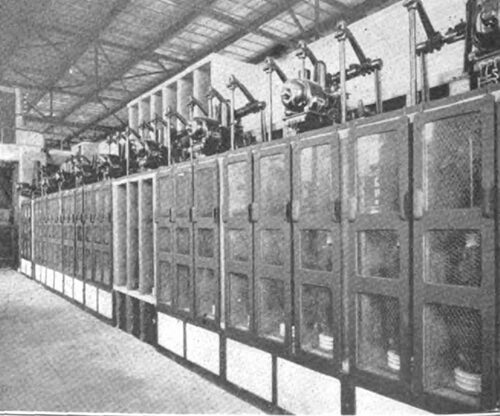
| |||
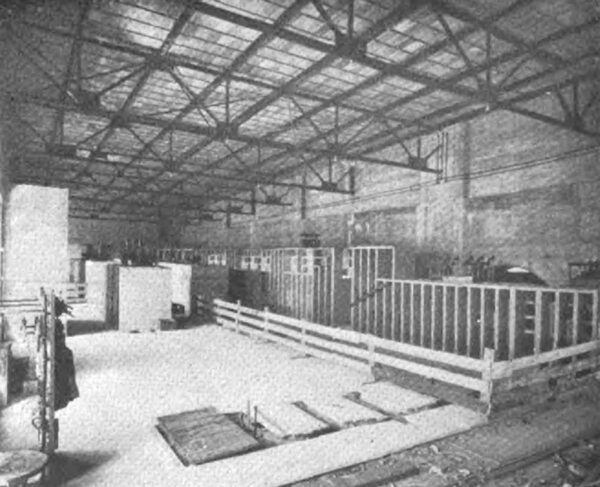
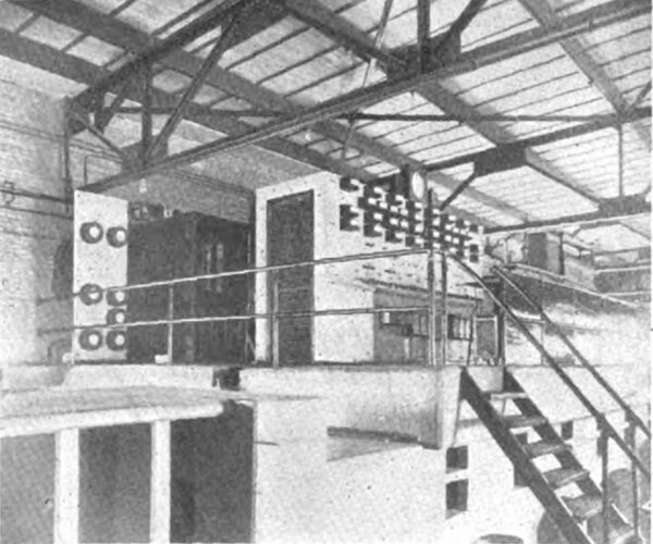
| Fig. 3--Bus Compartments and Oil Switches. |
The headgates are of the roller type of special design, permitting quick and easy operation. The gates are made up entirely of steel, with the exception of the wooden bottom bumper beam, and move on rollers of gray iron 9 in. in diameter turning around brass bushings. The rollers are greased from the centers of the bearings by pressing fat through the roller axle. Located longitudinally over the gates is a 5-in. motor-driven shaft made up of 20-ft. lengths, connected alternately by standard flange couplings and placed so that vertical racks on the gate stems engage on the shaft. The shaft runs through the entire length of the gatehouse and is capable of lifting the four gates of one unit together under normal water conditions in about one minute. Provision is made so that the shaft can be uncoupled and the gate dropped by its own weight, the speed of descent being controlled by a friction brake. Two 30-hp direct-current motors, one at each end, drive the main shaft, and a third motor will be installed when the other water wheels are added. A hand drive has been provided for emergency use in case the motor drive should fail.
| |||
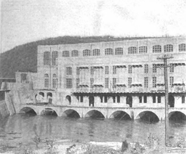
| Fig. 4--Generating Station and Dam. |
| |||
| Fig. 5--Transformer House and Tailrace. |
Ordinarily a gate is lifted by starting the motor and throwing a clutch in by hand at each gate. It is also possible to bring the main shaft in such position that the clutch can be thrown in while the shaft is not running, the motor being started with one or two gates connected to the main shaft. The closing of the gate can best be effected by releasing the brake on the hand lever and lowering the gate as far as it will go by its own weight, then throwing in the clutch on the main shaft and driving the gate to a firm seat on the sill. In addition the clutch may be thrown in first, in which case the additional friction on the gate has to be overcome by the motor as long as there is any negative movement, after which the brake will be released. An adjustable brake on a combined brake pulley carries a special friction lining of rubber, and is fixed to a cast-steel lever keyed on a small shaft, on one end of which is a hand lever and on the other a lever for a solenoid dropping device and an adjustable spring for keeping the brake tight. The solenoid for the dropping device can be operated from the benchboard by pulling a switch, and the dropping speed can be so arranged that the gates reach the bottom without any damaging jar to the gate or hoist. This dropping device is used for emergency only.
POWER HOUSE.
The power house, gatehouse and transformer house are finished for six units, including rheostat and switchboard galleries, compartments for transformers and other apparatus. All of the headworks, foundations, etc., are completed for a 135,000-hp development, the only work required to prepare the power house for the full installation being an addition to the present superstructure. At the present time there are six units installed and in operation. The power house is 48 ft. wide and will be 500 ft. long inside, with a floor 14 ft. below the crest of the dam. The penstocks, wheel chambers and draft tubes are formed entirely of concrete. The wheel chambers are 22 ft. wide and 33 ft. high, and from them two draft tubes, one above the other, are carried to the tailrace.
The waterwheels are of the vertical shaft, inward and downward flow Francis type, built by the I. P. Morris Company, of Philadelphia. Each of the main units is capable of developing 13,500 hp when operated under a head of 53 ft. and with 80 per cent gate opening. When running at its rated load and at 94 r.p.m., each turbine takes about 2700 cu. ft. of water per second. At times of ordinary flood the minimum head available will be 50 ft., and at times of low water the available head will be between 60 ft. and 65 ft. Two wheels are mounted on a single shaft of forged steel, and the entire weight is carried on a roller bearing supported by a casting set into the masonry. The draft tubes of the upper and lower wheels come out together below the level of the standing tail-water, so that it is possible to get at the upper wheel by closing the headgates. When the lower wheel requires attention stop logs may be used to cut off the tail-water, and the draft tube may be drained by electric pumps. The design of the wheels is such that with the available head reduced to the possible minimum during extreme floods, the turbines are capable of giving their rated output with 100 per cent gate opening.
ELECTRICAL EQUIPMENT.
Five of the generators installed are of General Electric manufacture, and one was built by the Westinghouse Electric & Manufacturing Company. All of the machines are of the vertical waterwheel, internal-revolving-field type, delivering three-phase alternating current at 11,000 volts and 25 cycles. The machines are Y-connected, with a lead for grounding the neutral. Three of the General Electric machines are rated at 7500 kw, and the other two are rated at 10,000 kw. The Westinghouse machine is rated at 12,000 kw. In all of the machines the generator voltage is controlled by motor-operated field rheostats and the excitation is automatically controlled by Tirrill regulators. Pneumatic brakes are provided for stopping the machines, the brakes bearing on the revolving field ring.
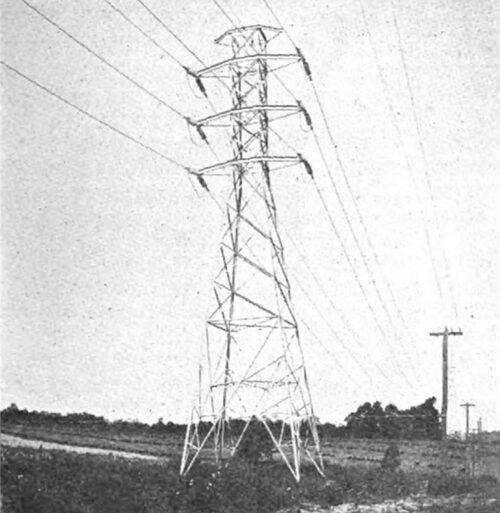
| |||
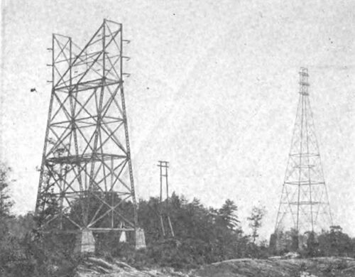
| Fig. 6--Dead-Ending Tower and River-Crossing Tower. |
Excitation energy is supplied by three machines, two vertical waterwheel-driven units rated at 400 kw, 250 volts and 240 r.p.m. These are compound-wound machines of General Electric manufacture and are fitted with interpoles. The third exciter is a Westinghouse horizontal motor generator set, consisting of a 500-kw, 250-volt compound wound, interpole, direct-current generator, mounted on a common frame with and direct-connected to a 750-hp, 10,500-volt, three-phase, 25-cycle, 750 r.p.m. synchronous motor. lead.
TRANSFORMERS
There are six General Electric 25-cycle, three-phase, 11,000-70,000-volt transformers installed. The transformers are delta-connected on the low-tension side and star-connected on the high-tension side, with a grounding neutral Four are rated at 7500 kw and two are rated at 10,000 kw. The transformer house is located south of the power house and is carried by arches spanning the draft tube outlets in the tailrace. Provision is made for bringing the transformers into the generator room and under the main crane in case repairs are necessary. The general layout does not differ much from standard practice, and the scheme of connections from the generators through the transformers to the transmission lines and to the terminal station in Baltimore is shown in Fig. 7.
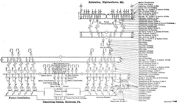 |
| Fig. 7--Wiring Diagram for Generating Station, Transmission Line and Substation. |
The barriers for the high-tension apparatus in the transformer house are built entirely of reinforced concrete. The compartments are located on both sides of a 12-in. division wall about 110 ft. long and the shelves and barriers are 4 in. thick.
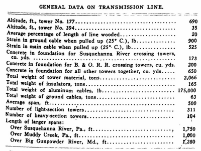
TRANSMISSION LINE.
The transmission line is 40 miles long and is built in the most substantial manner. The line is strung over 415 four legged galvanized steel towers made by Messrs. Milliken Bros., Milliken, Staten Island, N. Y. Two types of towers are employed, heavy-section and light-section towers. Heavy-section towers are used where the span is over 700 ft. and where there is an angle in the line. In straight, flat country one heavy-section tower is placed every mile. The six main cables, three for each line, are placed in two vertical planes, spaced 15 ft., and the distance between wires in the same plane is 7 ft. On the top of the tower provision is made for stringing two ground cables, but at present only one, which is clamped to the center of the tower, is installed. The standard height of towers is 44 ft. to the lower cross arm, and the total height from the ground to the ground cable is 62.5 ft. It was found desirable, due to the rolling character of the country through which the line passes, to make use of 10-ft. and 20-ft. extensions in some places, so as to maintain as nearly as possible a standard span.
| |||
| Fig. 8--Benchboard at Baltimore Terminal Station. |
| |||
| Fig. 9--Oil Switches at Terminal Station, |
All of the light section towers have one of the four legs bolted to a steel tripod set 6 ft. in the ground, and only where unusual conditions in the ground made it necessary was concrete used. All heavy towers have each of their four legs bolted to angle irons set in concrete.
The six conductors consist of 300,000 circ. mil 19-strand aluminum cables, and the ground wire consists of a 38-in. double galvanized steel cable composed of seven strands. The insulators are of the suspension type, made by the Ohio Brass Company. On each light section tower five-unit insulators are used for supporting each cable, while on the heavy-section towers six units are used for dead-ending each cable. Special towers are employed at certain places along the line, notably on the island near the station, where a 120-ft. tower is used, and also near Baltimore, where the lines cross the railroad right-of-way.
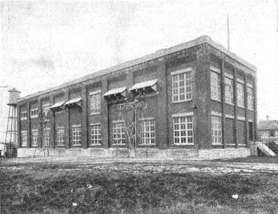
BALTIMORE TERMINAL STATION.
The Baltimore terminal station is located in the suburbs at Highlandtown, Md., and is built of brick, with footings, base wall, top coping, window sills and lintels, high-tension windows, floors, high and low-tension bus compartments as well as all barriers and transformer compartments, made of concrete.
| |||
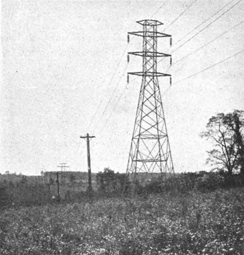
| Fig. 10--Standard Strain Tower. |
| |||
| Fig. 11--Standard Transmission Tower. |
The building is now 194 ft. 10 in. long, 54 ft. wide (inside) and 51 ft. high. Provision has been made for a 44-ft. extension on the north end, which will give the building its final quota of eight 10,000-kva transformers.
The ground floor of the building is taken up by the high tension bus compartments, mains and station service transformers and a chamber with pumps for handling trans former cooling water, oil-treating outfit, also oil-handling pump and vacuum and compressed-air pumps. Along the entire length of the west side of the building is a standard gage railway track, also a wider track with trucks for handling the transformers. All the piping is placed between and below the standard-gage track in a suitable pipe trench covered with reinforced concrete slabs. The first floor contains the transmission-line entrances, high-tension oil switches, low-tension oil switches and bus compartments, outgoing feeder compartments, charging set and storage battery with battery panels. The benchboard and meter panels are on an elevated platform underneath which is an electrically driven crane for handling the transformers.
ELECTRICAL EQUIPMENT AND CONTROL.
The two three-phase circuits of the transmission line enter the substation on the west side, the lightning arrester horn-gaps being installed on steel towers outside, while the electrolytic cells are placed inside. Each circuit goes through disconnecting switches, choke coils and series. transformers to a 70,000-volt automatic motor-operated oil switch, then through disconnecting switches to the two sets of high-tension busbars. These buses have oil section switches in the middle, with disconnecting switches on each side and oil tie switches at each end of station with bus knife switches for cutting out the oil switch. The buses are made of copper tubing, I in. by 7/8 in., supported by post insulators, and are in a concrete bus structure.
 |
From the two sets of high-tension buses, connection is made through disconnecting and oil switches to the high tension side of the 10,000-kva transformers; from the low tension side the leads are taken through oil and disconnecting switches to the two sets of low-tension (13,200-volt) buses. The low-tension buses, which are made up of two bars of 3-in. by 1/4-in. hard-drawn copper, have section switches in the middle and tie switches at each end, like the high-tension buses. All connections from the buses to the switches are made with copper tubing. From the buses leads are taken through disconnecting and oil switches to the three-phase outgoing feeder compartments. These compartments are occupied by the various series and shunt transformers for the meters and relays and also disconnecting switches. From the feeder compartments the leads, made up in one 13,200-volt lead-covered cable, are taken through clay ducts to a cable vault and thence to the underground distribution. A storage battery provides control and operating energy for the various oil switches.
| |||
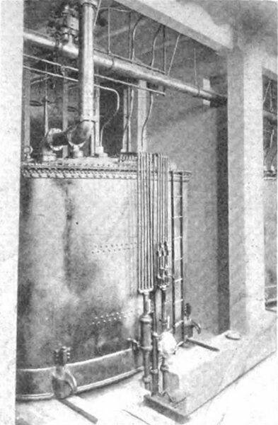
| Fig. 12--Transformer at Baltimore Substation. |
The benchboard is made of blue Vermont marble and has eight panels-both front and back. The front panels have an upper section on which are located the various meters; on the desk section are the control-switch indicating lamps and mimic buses; the lower section has the time limit relay for operating the various oil switches. rear panels are located 4 ft. back of the front ones and all supported from a pipe framework. Back panels are made up in three sections and have mounted on them the curve-drawing wattmeters, voltmeters, station service switches, etc. Separate panels are provided for mounting the outgoing feeder meters.
TRANSFORMER COOLING SYSTEM.
Cooling water for the 10,000-kva transformers is pumped from a well on the premises to a cistern and from there to a tower tank 75 ft. high, from which it flows to the trans former inlets. The warm water from the transformer is pumped to the roof, where it is cooled by spraying, after which sufficient of it is allowed to run into the cistern and mix with the cold water from the well to keep the cooling system in operation.
The transformers are connected through 8-in. piping and back-pressure valves to an 8-in. relief header, which allows the gases or foaming oil to escape in case of injury to the transformers. The back-pressure valves prevent impure oil from getting into uninjured transformers.
TRANSFORMERS.
The five transformers at present installed are of the Westinghouse oil-insulated, water-cooled type, rated at 10,000 kva on balanced load and designed to step down the potential from 60,000 volts to 13,200 volts. They are 25-cycle, three-phase machines delta-connected on the high tension side and star-connected on the low-tension side with grounding neutral lead.
| |||
| Fig. 13--Line Entrance at Baltimore Terminal Station. |
There are two small transformers of General Electric make rated at 50 kw each, which reduce the potential of the three-phase, 25-cycle main secondary circuit to 220 volts for station service. In addition there is a 10-kw motor-generator set made up of a 15-hp induction motor and a 10-kw, 250-volt generator, the output of which is employed to charge a 124-cell Gould battery.
The output of the system is at present used by the lighting and railway companies of Baltimore, and work on extensions to the system is now in progress. Mr. J. E. Aldred is president of the Pennsylvania Water & Power Company and Mr. F. A. Allner is general superintendent. The company maintains offices in New York and Baltimore.
