[Trade Journal]
Publication: Electrical World
New York, NY, United States
vol. 60, no. 22, p. 1141-1144, col. 1-2
HYDROELECTRIC ENERGY FOR COAL FIELDS.
Plants Nos. 2 and 4, Comprising Initial 29,000-hp Installation of the Appalachian Power Company on the New River.
Plans for Group of Hydroelectric Stations with Common Step-Up Transformer House-88,000-Volt Transmission Lines with "Wishbone" Cross-Arms and Suspension Insulators.
OF the five water-power sites, aggregating 225-ft. drop and 75,000 hp, which the Appalachian Power Company has planned to develop on the New River in Virginia, two plants, totaling 29,000 hp, are now completed and in operation, developing hydroelectric energy for transmission throughout the surrounding rich mineral and agricultural country. The developments first finished are known as No. 2 and No. 4 respectively, and from them as a nucleus 88,000-volt lines have been built to Bluefield and Coalwood, W. Va., and to Saltville and Roanoke, Va. Of special interest in this lay-out is the provision of a common transformer house which receives the 13,000-volt, 60-cycle output of the several water-power plants, regulating the energy developed, and stepping it up to 88,000 tee volts for transmission. Four of the five sites are located within a distance of 5 miles, and arrangements have been made for extending the transformer station to house additional equipment as the rest of the plants are built.
| |||
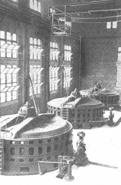
| Fig. 1--Interior of Power House. |
DEVELOPMENT AT MOUNTAIN ISLAND.
Site No. 4 was the first plant to be completed. The development here utilizes Mountain Island in the New River, a spillway dam 1000 ft. long having been built across the main channel of the stream at the head of the island. In this way the narrower channel on the north side of the island has become a natural headrace leading to the retaining dam and power house which close the north channel at the foot of the island proper.
From the plant a tailrace has been excavated for a distance of 1800 ft. down stream, adding 15 ft. of head and making the total fall available at the turbines 38 ft. To excavate this tailrace required the removal of 66,000 cu. yd. of rock. The spillway dam is of the solid concrete, gravity-section type, keyed into and seated upon the solid rock of the river bottom. In average section the spillway crest is approximately 17 ft. high, to which can be added 5 ft. of flash boards. From the principal concrete mass there project thirty concrete piers at 32-ft. intervals, carrying the flash board bridge at a height 12 ft. above the sill and well out of the way of any possible high water. The spillway dam is provided with a base 26 ft. wide, and its upper flow surface is arranged with a double curve to discharge the overflow, which descends to the level of the lower rapids.
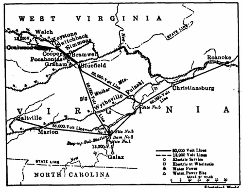 |
| Fig. 2--Map of Present 88,000-Volt and 13,200-Volt Lines. |
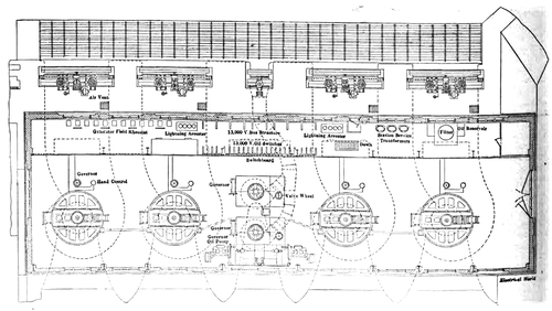 |
| Fig. 3--Plan of Power House No. 2. |
Concrete has also been used for the foundations and bulk head walls of the power house, the superstructure being of steel and brick. The building measures 132 ft. by 61 ft. in plan section and provides for three main 3000-hp units and two exciter sets, all of which have been installed. The waterwheels are of the vertical-shaft, single-runner Francis type and were built by the I. P. Morris Company, Philadelphia. They run at 97 r.p.m. and drive General Electric 13,200-volt, 60-cycle, three-phase alternators. Each turbine has its own 13-ft. by 21-ft. inlet passage, leading from the tracks and headgates, molded in the solid concrete. The exciters are supplied from a common inlet chamber which is equipped with branch penstock tubes.
NEW RIVER PLANT NO. 2.
A mile and a half from the No. 4 development above referred to is the No. 2 site, the second plant to be completed of the initial development. This station utilizes, a hydraulic head of nearly 50 ft. and contains four 5000 kw waterwheel sets. Its solid concrete dam backs up the water to the tailrace level of the first-mentioned development, a distance of almost 3 miles measured along the bed of the stream, which here swings in a broad bend to the south. The incident rise in level of the stream sur face caused by the No. 2 dam has necessitated the relocation of nearly 4 miles of the original grade of the Norfolk & Western Railroad's North Carolina branch.
| |||
| Fig. 4--Sluice Gates. |
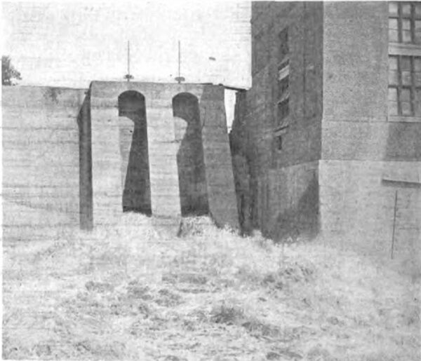
At the second site the power-house bulkhead wall forms a part of the main dam, which thus has an overall length of nearly 750 ft. The spillway section, 530 ft. long, has a height of 50 ft., measured from its sill to the footing on the bedrock. The gravity section of the structure has a base 56 ft. long and is designed with a 2.5 per cent factor of safety against overturning. At intervals of 30 ft. piers extend 15 ft. above the spillway level, carrying the foot-bridge for operating the Tainter gates and flashboards. Six of these spans are provided with Tainter gates and the other nine are arranged for flashboards.
Above and at the side of the power house an auxiliary spillway has been built by cutting through a ridge to a natural sluice or gulley paralleling the main stream. Additional spillway length of nearly 200 ft. is secured in this way, providing for six clear 31-ft. spans of flashboards, similar to the arrangement used on the main dam.
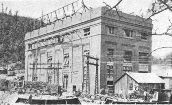
| |||
| Fig. 5--Exterior of Transformer House. |
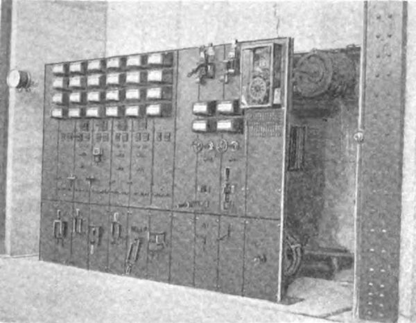
| |||
| Fig. 6--Switchboards. |
| |||
| Fig. 7--Turbine-Driven Exciters in Power House No. 4. |
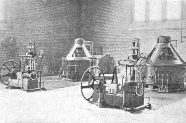
The power-house measures in plan 170 ft. by 50 ft., not including the concrete foundations and bulkhead containing the headgates and trash-racks. The superstructure of the station building is of steel and brick. It contains four 5000-hp single-runner Francis type waterwheels, built by the Morris company, each driving a 13,200-volt, 60-cycle, three phase General Electric generator at 116 r.p.m. The concrete draft tubes molded as a part of the foundations discharge into the 90-ft. tailrace excavated from the solid rock. Sixteen thousand cubic yards of concrete were used in the plant foundations alone, and 33,000 cu. yd. were required for the spillway. With the reservoir regulation obtainable by means of the Tainter gates, it is possible to store and conserve the flow of the river for any reasonable daily load factor. Midway between the two pairs of 5000-hp main units there have been installed a pair of turbine-driven exciter sets. These exciter sets are fed by means of a separate penstock.
STEP-UP TRANSFORMER SUBSTATION.
Near the No. 2 site just described is located the step-up transformer substation, whose position is thus nearly midway of the 13,200-volt lines, connecting it with the future four generating stations, two of which are already operating. The electrical control equipment of these plants, it will be noted, is restricted to that associated with the generators and 13,200-volt buses, all of the high-tension and transforming apparatus being installed in the step-up station just referred to. Pulaski
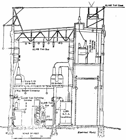 |
| Fig. 8--Cross-Section of Step-Up Transformer House. |
The present equipment comprises four 6000-kw water cooled three-phase General Electric transformers, with 13, 200-volt primaries and 88,000-volt secondaries. Aluminum cell lightning arresters, with outdoor horn-gaps mounted on the roof, protect the 88,000-volt entries. Vertical roof type insulators admit the arrester taps, the cells themselves being located in a separate gallery above the switch room. The main line conductors are carried on over the station roof on strain insulators and drop down on the far side to wall entries, connecting through choke coils to the Kilo oil switches. Provision is made for two three-phase circuits. Similar oil switches connect the transformer secondaries to the substation buses, which are carried overhead in the switch room. Below the second-story switch room are the transformer compartments and in a corridor are the 13,200-volt switching apparatus, aluminum-cell arresters, etc.
88,000-VOLT TRANSMISSION LINES.
From the step-up substation there radiate nearly 200 miles of 88,000-volt, three-phase circuits. The familiar Byllesby "wishbone" type of cross-arm construction has been used throughout on these lines, although with several modifications from the form first adopted several years ago. Instead of steel angles, 6-in. by 4-in. oak timbers are used for arms, being pinned to the pole by through-bolts at their center points. The original construction, it will be recalled, employed a two-thirds spacing of the pins. The bolts for these cross-arms also hold in place the 3-in. by 3-in. by 3/16-in. steel-angle bayonet, 7 ft. long, which supports the ground cable 2 ft. above the pole top. This steel bayonet is earthed by a ground wire running down the pole and ending in a coil buried at the butt. Forty-five-foot poles have been adopted as standard. Nineteen feet below the pole peak and 8 ft. below the lowest line conductor a pair of telephone wires are carried on pole brackets. Four-disk suspension insulators are used, the distance between conductors on the same side of the pole being 8 ft. and the remaining triangular spacing 10 ft. between wires.
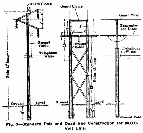 |
| Fig. 9--Standard Pole and Dead-End Construction for 88,000 Volt Line. |
The Bluefield transmission line crosses the Big Walker Mountains to the north of the group of developments and extends across the state line into West Virginia, reaching a terminus at Coalwood. Among the other towns served by this circuit are Welch, Keystone, Switchback, Bramwell, Simmons, Cooper and Pocahontas, W. Va., and Graham and Wytheville in old Virginia. Another circuit extends almost 45 miles due west to Saltville, passing Marion en route. Roanoke, 65 miles northeast of the step-up substation, is reached by a line that takes in Christianburg on the way, and from a point at the No. 5 site, 20 miles distant, an 88,000-volt tie line branches off to Bluefield by the way of Pulaski. Substations are in operation or being built at Roanoke, Pulaski, Bluefield, Switchback, Coalwood and Saltville. In the centers of the coal-mining load and at points like Wytheville and Galax low-tension substations have been built. For the secondary transmission circuits 13,200 volts has been chosen as standard.
SALE AND USES OF ENERGY.
The territory in Virginia and West Virginia centering about these two developments is rich in many varieties of minerals, including the famous Pocahontas coal, iron, zinc, copper, salt, gypsum, glass sand, clay, etc. With water power available, the mining properties themselves are not only being developed at a more rapid rate, but the sur rounding communities are feeling the stimulus and many industrial plants are being established.
The Appalachian Power Company has acquired the electric-lighting and street-railway systems of Marion, Wytheville, Pulaski, Pocahontas, Welch and Keystone and the street railway at Bluefield, all of which are within 50 miles of the water-power developments. A contract has been closed with the Roanoke Railway & Light Company for energy to operate its system at Roanoke. The steam plant at this point will also serve as a relay station for an auxiliary source of power in case of interruption to the water power operation.
By the terms of its contract with the Pocahontas Consolidated Collieries Company the hydroelectric corporation acquires the use of the collieries' 7500-hp steam turbine plant at Switchback, which will be employed as a reserve and to supplement power from the hydraulic developments. Other concerns in the coal fields which have contracted for the purchase of central-station energy are the Virginia Pocahontas Coke & Coal Company, the American Coal & Coke Company, the Zenith Coal & Coke Company, the Crystal Coal & Coke Company, the West Virginia-Pocahontas Coal Company, the Coaldale mines, etc.
The Appalachian Power Company is operated by H. M. Byllesby & Company, engineers and managers, Chicago. Mr. H. W. Fuller is vice-president and general manager of the power company, whose executive offices are at Blue field, Va. Messrs. Viele, Blackwell & Buck, New York, were the consulting engineers in charge of construction of the plants, high-tension lines and high-tension substations. above described. H. M. Byllesby & Company have had charge of engineering and construction in connection with the various electric plants purchased by the water-power company and the distribution systems in the coal fields.
