[Trade Journal]
Publication: Scientific American
New York, NY, United States
vol. 108, no. 14, p. 312-313, col. 1-3
 |
Suspension Insulators Suitable for 110,000-volt Transmission
Tests Showing the Weaknesses of Standard Types
By Joseph B. Baker
THE constant tendency to Increase the voltage of electric transmission lines in order to deliver energy over longer distances and with reduced lines loss has presented for solution many problems of insulation. Both the terminal apparatus and the connecting lines must be insulated so strongly that the high pressures employed, and especially the abnormally high potentials due to sudden and transient surges, will not result in breakdown of line or apparatus with its serious consequences. The resistance and dielectric strength of insulations used in electrical machinery at generating and sub-stations generators, transformers, rotary converters, etc. has been well worked out by designing engineers and electrical manufacturers in response to the demand for higher and higher voltage equipment; but the protection of the line itself, which is not localized in a small space under a sheltering roof, but runs for many miles through the open country, strung overhead on poles and exposed to all atmospheric conditions, has been in a comparatively backward state. In the old days, when generators and transformers were built with shellacked cotton-insulated wire windings, the lines from the power station were strung on ordinary glass insulators, like those used for telegraph and telephone wires. Later, when better insulations for the machinery were developed in recognition of the fact that high and durable insulation is an essential of continued and economical operation, the pole lines likewise received attention, and special porcelain insulators began to be used; but up to a very recent date high-tension line insulators nowadays consisting of a series of insulator sections, or "units," affording a long and high resistance barrier against leakage of electricity have been designed more in accordance with the individual views of their makers than with any definite electrical and mechanical requirements.
| |||
| Type D With Hook Unprotected. |
In a paper recently presented before the American Institute of Electrical Engineers, Mr. P. W. Sothman of New York describes an investigation of a number of different types of high-tension suspension insulators that he made in order to select a suitable high-tension insulator for a transmission line operating at 110,000 volts a voltage at which the question of insulation is of the greatest importance, since very little reliable data was available as to the operation of insulators for potentials above 80,000 volts.
| |||
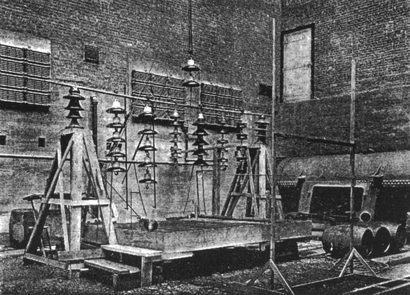
| Testing Platform for Suspension Insulators. |
At the outset of this investigation, upon visiting the different insulator factories and witnessing manufacturers' tests on insulators which they proposed for this work, it was clearly seen that the most widely varying methods of testing were employed, so that an insulator showed entirely different results, depending on where and, by whom it was tested. There seemed to be no recognized standard in the testing conditions or in the method or interpreting the effects observed; so that it was impossible to arrive at definite conclusions of value in the actual installation of the insulators on a power transmission line. For the new investigation it was therefore determined to establish absolutely unvarying conditions and a definite line of reasoning to be followed in classifying the results obtained.
| |||
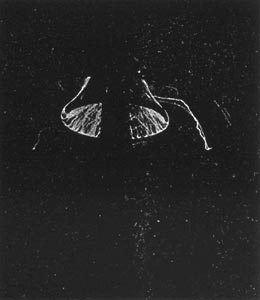
| Type D Protected by Bottle-Shaped Shield. |
The testing equipment was one having plenty of power (as well as high voltage), and was so arranged that the conditions could be controlled and changed at will. For the open air electrical tests of the suspension insulators, a piece of gas pipe was supported horizontally, resting at each end on a 60,000-volt pin-type insulator at a convenient height above a large platform. The general view of the testing apparatus for suspension insulators shows several of these insulators hung vertically from this gas pipe support; but the insulators were tested one at a time, being placed in the middle of the support while under test, with all the other "candidates" crowded to one side out of the way. The same platform and arrangements were used for the electrical tests of the strain insulators that were investigated, except that the insulator under test was held by tackles in a horizontal position with two other insulators at the ends of the tackles to prevent leakage to ground. For supplying the testing voltage two 50-kilowatt, 150,000-volt transformers were used, giving a maximum voltage of a little over 330,000 (330 kv.). The voltage was controlled by a water rheostat in the low-tension circuit, and readings were taken on a special voltmeter calibrated with spark-gap.
The tests on each insulator comprised "dry tests" consisting of a flash-over test on each section of the insulator in order to exclude defective or punctured units, and a" potential test on the complete insulator and on a less number of sections than the total number in the insulator; wet test (insulator exposed to artificial rain); test of all of the insulators in parallel, in order to observe closely relative performance when exposed to identical voltage and conditions; puncture test, with the insulator immersed in oil, since the potential required to puncture a sound insulator is greater than the flashover voltage; test of mechanical strength made with a simple pulling contrivance and dynamometer. An interesting feature of the work was the method of simulating rain, in the wet tests by an adjustable comb of water-pipe nozzles arranged to shower the "rain" over the insulator. By using two groups of nozzles and adjusting their distance from the insulator under test, the angular precipitation of their streams and the amount of rain supplied per minute (measured by a special rain-gage) was placed under perfect control.
The electrical tests illustrated were made at night and in complete darkness, so that distinct observations could be made of all electrical effects by the eye and by the camera; and the photographs which constituted a permanent record of the work were identified by the time shown by a clock placed near the insulator under test. The voltage applied to the insulators was raised by successive steps. Assuming that the luminous display was in proportion to the power leaking past the insulator, it was deemed fair to judge the quality of the insulator by comparing the amount of the display and the voltage that was required to give same. In deciding the net relative value of a given insulator and the influence of its design, other observations were considered; the gradual increase of luminosity, or the appearance of a sudden display, on raising the voltage; the appearance of the display at certain points and not at others on the insulator, etc. The five types of suspension insulators as seen by daylight, and one of the strain insulators that was tested, are shown herewith. The photographs on the opposite page illustrate the performance of the insulators under rain at an angle of 4.5 degrees and at the rate of one half inch of water per minute.
 |
| Suspension Insulators Submitted for Test. Types A, C, D, E, and F Are Regular Suspension Insulators, Type B Being A Proposed Strain Insulator. |
Type A met the mechanical requirements (by showing a breaking strain exceeding 8,000 pounds), but not the electrical requirements. As the voltage was raised a discharge became visible at 150 kilovolts, and the insulator broke down at 160 kilovolts. The appearance of this five-unit insulator at 160 kilovolts shows the imminent breakdown as due to excessive leakage, the entire insulator virtually becoming conducting. There was another important feature characteristic of every insulator having metal fittings which are in the least degree non-symmetrical about the axis of the insulator, viz., the uneven static field or dielectric stress, most intense at projecting metal points and always causing premature failure of the insulator; the discharge of the insulator is started in almost every case at the projecting point.
Type C insulator also showed up better mechanically than electrically, although it was judged to be too fragile in ordinary handling. It began to show luminous effects at 225 kilovolts, and failed by flashover at 265 kilovolts. This insulator furnishes another instance of uneven dielectric stress, the effect of which is very marked in the reproduced photograph of the insulator in the act of breaking down particularly at the point of discharge at the left of the cap in the second section from the top.
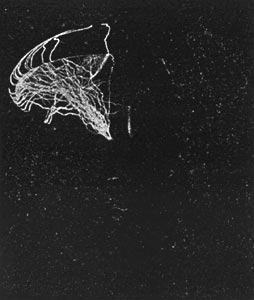
Type D is shown breaking down at 280 kilovolts by flashover. The illustrations of this insulator under test show the localized discharges from projecting points and backs of the hooks used to link the sections together, and the marked effect of protecting the hook by a bottle-shaped metal shield giving a symmetrical instead of a non-symmetrical metal surface.
The eight-unit Type E insulator is shown in the act of falling at 310 kilovolts in consequence of strong leakage from section to section. Heavy discharges are occurring at the cotter pins in the caps.
Type F, an insulator of European design and manufacture, made the best showing of all. The photograph shows this five-section insulator flashing over from section to section at 300 kilovolts. The performance of each section, revealed to the camera by the luminous discharges, presents an interesting study. This insulator failed to meet the mechanical tests only because the cement joining the different pieces in each unit had not properly set. It met the electrical requirements well, showed high-class workmanship and material.
Final selection of the Type E insulator was made in consideration of its good electrical points as demonstrated by the tests on the eight-section insulator, and because better deliveries could be made for the actual line construction than could be expected for the foreign-made insulator, Type F. The large number of open spaces in this unit are of advantage. Although the insulator did not meet the mechanical specification requirements (owing to the fact that the cement had not properly set, the insulator broke at an average stress of 7,650 pounds, the required creaking stress being 8,000 pounds), it was judged to be strong, light, durable, and compact, and susceptible of improvements by slight changes in the design. A subsequent increase in diameter increased the electrical efficiency substantially, and the method of connecting units together was modified so as to present a smooth and symmetrical surface to prevent premature discharge.
The strain insulator Type C did not meet the requirements under the wet test by reason of the excessive leakage at potentials below the specified standard of 220 kilovolts (twice the line voltage). Other types that were submitted for test having also failed, a ten-unit Type E insulator, with a modified design of cap to increase the strength, was finally adopted aa the least unsatisfactory strain insulator to use.
