[Trade Journal]
Publication: Stone & Webster Public Service Journal
Boston, MA, United States
vol. 16, no. 1, p. 39-44, col. 1
ECONOMY IN THE OPERATION OF 55,000-VOLT INSULATORS
BY M. T. CRAWFORD
The final measure of success in a transmission system is the cost of securing the desired performance therefrom.
The failure of line insulators from breakage or electrical causes is a menace to service performance, and may be the cause of heavy maintenance expense if the failures are frequent and repairs must be made under emergency conditions. The problem of securing satisfactory and economical operation from lines having gradually weakening insulators has recently become an important one on some systems.
This paper outlines briefly the operating experience on several of the older lines of the Puget Sound Traction, Light and Power Company system, and describes methods employed to secure satisfactory performance economically.
General Data
Nominal voltage, 55,000; non-grounded neutral; 60-cycle, three-phase current. All pin type insulators are of the design shown in Fig. 1.
Line A. In service 10 years; from Electron generating station to Tacoma. Length 31 miles (49.8 km.). Number of insulators 4,450. Poles 40 ft. (12 m.), set on average spans of 125 ft. (38 m.). Wires spaced six ft. (1.8 m.). No. 4/0 B. & S. copper 21 miles (33.7 km.); No. 0 B. & S. copper 10 miles (16 km.). Insulators cemented on iron pins. Wooden pins screwed in insulators were used on a portion of this line when first installed, but have nearly all been replaced at this date with iron pins.
Line B. In service 10 years; from Electron generating station to Seattle. Length 47 miles (75.6 km.). Number of insulators 6,850. Poles 40 ft. (12 m.), set on average spans of 125 ft. (38 km.). Wires spaced six ft. (1.8 km.). No. 4/0 B. & S. copper. Insulators cemented on iron pins.
Line C. In service five years at 55,000 volts; from Snoqualmie generating station to Everett, Seattle and Tacoma. Length 160 miles (257.4 km.). Number of insulators 17,350, 4,550 of which were in service at 30,000 volts for two years previous to the 55,000-volt service.
Poles 35 to 55 ft. (10.6 to 16.7 m.), set on spans from 130 to 300 ft. (39.6 to 91.4 m.). Wires spaced seven and nine ft. (2.1 and 2.7 m.), and vary in size from No. 4 B. & S. copper to No. 4/0 B. & S. aluminum. Insulators screwed on iron pins.
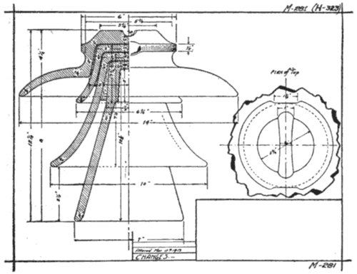 |
| Fig. 1. Insulator for 60,000-V. Construction |
Operating History
Line A. The insulators originally installed on Line A were among the first of their kind and voltage to be made, and the art of high-voltage porcelain manufacture was not well understood at that date. Their appearance indicates that the clay was worked quite dry and that probably the mixture contained a much lower percentage of china clay than is now used. Many samples show a lack of homogeneity in the ware and irregularities of surface, and firing cracks are visible under the glaze. The shells were given a moderate test at the factory and shipped to Tacoma, where they were cemented together and the assembled insulators subjected to a dry test of 120,000 volts. Difficulties with the testing equipment made it necessary to put a portion of the insulators on the line without test. There were failures from time to time during the test, but as it was considered unusually severe, trouble was not anticipated.
Electrical failures began to occur within a short time after installation, especially during line surges and in wet weather, and have continued from time to time to date. The larger shells crack radially and leakage over the smaller shells burns off crossarms. These cracks stand upon perceptibly, indicating that there were shrinkage strains in the ware.
It has been necessary gradually to replace these insulators, until at this date 83 per cent of the original installation has been replaced.
Line B. The insulators on this line were purchased and installed under the same conditions as Line A, but were made at a different factory. The appearance of these insulators indicates a much better grade of porcelain with a smoother surface, but some samples of them do compare with the ware turned out of the factories today. Such of them as were tested showed a very small percentage of failures. For the first five years of operation very little trouble was experienced with these insulators, but later on they began breaking down occasionally and recently they have given a good deal of trouble, failing several at a time during an arcing ground at another point on the system. A large number of these insulators were put on Line A to replace failures of the original insulators thereon, so that the total installation of the ware purchased for Line B is about 8,200 insulators. Of these, the failures to date have totaled about 4 per cent, nearly half of which have been in the last year. These insulators do not usually have a large radial crack, but a small crack starts on the head or in the side groove and runs around on the top of the insulator. It seems that these cracks enlarge until a leakage current starts through the top two or three shells and discharges over the surface of the lower shell. The tendency of a brush discharge to pass in the positive direction more than the negative, has a rectifying effect on the leakage current. This results in a partly unidirectional current from the bottom shell to the pin, and signs of electrolytic corrosion of the pin head in the cement have frequently been found. Once started, this will soon crack the entire insulator, as the high tensile stress put on the porcelain by this internal expansion will lower its dielectric strength. In many cases insulators have been found which were leaking noisily, and when the line was killed and an examination made, the insulator was found intact, although a number of cracks were visible. As soon as the tie wire was removed, however, the entire insulator fell apart.
Line C. The insulators on this line were made at several different factories and are of as fine a grade of porcelain as can be obtained today. A representative of the company at the factory tested each shell separately, and the assembled insulator, to 120,000 volts for five minutes. Every insulator was given this test and examined for physical defects, and stamped by the inspector if accepted. To date there have been only three failures, and it is possible that these were partially broken in some other way before failure.
A large number of insulators have been installed on pole lines and steel tower lines built within the last few years on this system, which were tested as in Line C and screwed on iron pins, and there have been no failures. About 120 strain insulators, each consisting of three 10-in. (25.4-cm.) diameter link type disks with no cemented parts, have been in service at strain points for three years without trouble.
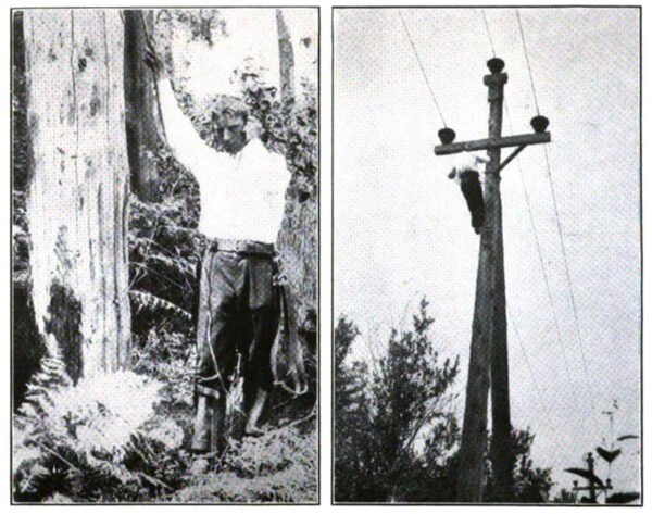
The expense of replacing outright all the Line B insulators was prohibitive, and they formerly were replaced one by one when they got to the point where the leakage currents could be heard from the ground. This was not entirely satisfactory however, as they were at an advanced stage of deterioration before this condition was reached, and frequently failed, causing an arcing ground that punctured other insulators, and a heavy charge against maintenance resulted on account of the emergency nature of the repair work. The first method tried was by using a megger, but no satisfactory results could be obtained unless the testing wire was over the leaking crack and this crack extended clear to the pin. Each insulator had to be untied and the testing work was very expensive and laborious. After considerable experimenting a device was perfected to locate these insulators at an early stage of the depreciating process, so that the work of replacing them could be done economically and before they broke down and damaged other insulators and interrupted service. This device is shown in Fig. (2) and consists of a pair of 2000-ohm wireless telegraph receivers, fitted up for the convenience and safety of the inspector in testing. The hand pick is driven into the pole about seven feet from the ground, and the sharpened pin driven into the ground several feet away. The receiver set is connected between these two, and if all insulators are sound there is a clear audible hum of the same tone as the telephone line, due to the shunting of a part of the capacity current of the insulators on the pole top. If, however, one of them is leaking, a scratching noise is superimposed on the hum, which comes and goes as the neutral shifts to and from the wire on the defective insulator. The inspector then proceeds up the pole and tests between each insulator pin and the center of the crossarm and thus locates the defective one. This device can be used in a similar manner on steel tower lines. Insulators can be found in this way which have only a very small crack started and which will not puncture on the test below 100,000 volts. Insulators with a crack clear around the head were taken off and tested, puncturing at from 60,000 to 65,000 volts, but no sound was audible from them while on the line without the use of the detecting set. One or two lower petticoats were usually found intact, the leakage current passing over their surface during the test until the puncture point was reached.
| |||
| Fig. 2-3. Showing Method of Using Defective Insulator Detecting Set. Hand Pick Consists of Insulated Tube With Sharp Pointed Steel Terminal on One End Which is Thrust Into the Pole or Crossarm. A Sharp Steel Pin Forms the Other Terminal, Which is Driven Into the Ground or Pole Under the Crossarm. A Fuse and Short Circuiting Jack With Plug on the Receiver Set May Be Inserted in the Circuit If There is Any Probability of A Considerable Voltage to Ground. |
Field books are kept with the record of the last test, and data on each insulator on every pole in Lines A and B. With practise the inspector can single out defective insulators which are at an early stage of the depreciating process. These tests can be made while the lines are in service, at very slight additional cost to the routine patrolling. Several hundred insulators can be replaced at a convenient time and the work organized so as to be done economically. By keeping at this work at regular intervals, failures in service can be practically eliminated.
It seems probable from the history of operation that the porcelain on Lines A and B was of lower dielectric strength originally than that on Line C, and that many of these insulators were therefore under an electric stress, which was a large percentage of their ultimate strength. Under these conditions the poorer insulators soon failed, and the better ones gradually weakened, to fail later. The best insulators, however, as on Line C, are being operated at a potential which is a small percentage of their ultimate strength and are showing no signs whatever of weakening or fatigue, although they have only been in service five years. The Line A and Line B insulators began to weaken in less time than this, and it seems that if any process of fatigue were under way, some signs of it would surely be in evidence among 17,350 insulators after five years' service. Although the evidence is not conclusive, it seems probable to the writer that electrical fatigue of porcelain only occurs where the ware is operated under electrical or mechanical or combined stresses which are too close to its ultimate strength. Insulators should be designed and individually tested to withstand at least two and one-fourth times line voltage; and care should be taken that at high potentials, where unit insulators are in series, line voltage is taken as the actual portion of the total voltage which comes on each particular insulator in the string. Where the gradient is not uniform and potential is concentrated more on some units than on others, these units should be designed accordingly and tested as above.
The use of cemented-in metal parts should be avoided in connection with porcelain insulators, thus eliminating any possible trouble due to electrolytic corrosion if leakage currents occur, or due to expansion and contraction strains of the different substances. The use of screwed-on pin-type insulators decreases the cost of replacing, and while not quite as suitable for heavy side strains, the use of strain insulators is better practise for such points.
