[Trade Journal]
Publication: Electrical Review and Western Electrician
Chicago, IL, United States
vol. 68, no. 25, p. 1130, col. 1-2
Improved Disk-Strain and Pin-Type Insulators
Invented by Louis Steinberger.
Because of the rapid increase in power transmission through high-tension lines special interest attaches to some radical improvements in the design and construction of disk-strain and pin-type insulators which have recently been invented and patented by Louis Steinberger, president and general manager of the Electrose Manufacturing Company, Brooklyn, N. Y. A few typical designs embodying these inventions are shown in the accompanying sectional illustrations.
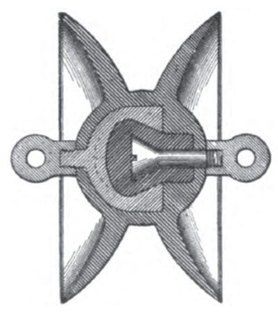
A simple form of disk-strain insulator is shown in Fig. 1. It will be observed that the insulating portion in this case consists of two smooth outwardly flaring disks which are united in the body portion of the insulator so as to form an integral insulating body completely inclosing the mechanical strain members. The latter are metallic and are arranged to interlock so as to form an extremely strong structure, such that even though the insulation were totally destroyed the line could not fall to the ground. The outer ends of the strain members, in this case shown as eyes, can be unscrewed and replaced by clevises, threaded studs, sockets, etc., to meet special requirements. Between the inner metallic strain members, and completely insulating them from each other, is an insulating filler made of fireproof composition with very high dielectric qualities.
| |||
| Fig. 1.--Section of Disk - Strain Insulator With Plain Disks. |
| |||
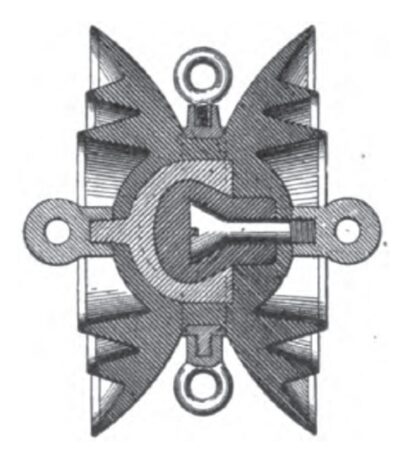
| Fig. 2.--Section of Strain Insulator With Collars on Disks. |
| |||
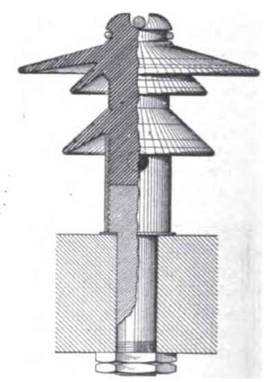
| Fig. 3.--Partial Section of Pin - Type Insulator With Improved Pin Mounting. |
Where it is desired to use a strain insulator on a line of much higher potential than that suited for the type of insulator shown in Fig. 1, the construction shown in Fig. 2 is employed. It will be observed in this view that the interior construction is similar to that already described. The chief feature of the latter modified type is that the disks are provided on their outer surfaces with outwardly extending ridge-like rings or collars, the whole being molded into a unitary structure. The object of these intermediate rings or collars is to increase the length of path between the ends of the strain members, thus making the device especially adapted to extremely high voltages. The design shown in Fig. 2 also shows that it is surrounded in the middle between the disks by a metallic ring to which are secured several eyes. This construction may be used for supporting arc lamps, etc., or where it is necessary to brace the strain insulator in several lateral directions.
A most important feature of these insulators is that the peripheral edges of the disks, and the outward edges of the intermediate rings or collars shown in Fig. 2, are provided with metallic annular shield rings. These serve to equalize the dielectric stresses and they also provide a convenient path for arcs, thus permitting the easy and quiet dissipation of their energy. These metallic shield rings also serve as elements of a condenser and thereby secure a uniform distribution of the electrostatic field about the insulator. In the case of abnormal electrical discharges, these shield rings also prevent puncturing the insulator, this being done without reducing the effective line insulation.
This capacity effect is also embodied in the design of the pin insulator shown in Fig. 3. Each of the flaring disks or petticoats is provided with metallic annular shield rings and the upper surfaces of these flanges have imbedded in them similar conducting shield rings. These various shield rings serve to dissipate thoroughly and rapidly any abnormal charge that tends to travel from the line conductor in the upper groove downward to the pin. These shield rings are arranged so that the discharge must pass over the surface of the flanges instead of through the body of the flanges OT the insulator. They likewise serve to uniformly distribute the electrostatic field. The general theory of this design is that these shield rings provide an interrupted conducting path from the line to the ground which consists of alternate ring sections of extremely high and low resistances, the latter serving to distribute the charge and therefore to protect the insulator from injury due to confinement of the charge to a narrow path, while the portions of high resistance provide the high impedances to the passage of normal line current which is necessary to prevent grounding the line itself. These metal shield rings also serve to give greater mechanical strength to the insulators themselves.
Another very important characteristic of this type of pin insulator is the improved mechanical construction of its support. It will be observed from the sectional view that the pin does not penetrate the insulating body of the insulator itself but ends at the base of this body. The lower portion of the insulating stem is molded within a metallic sleeve, which also surrounds the top of the pin and gives great mechanical strength, without reducing the high dielectric strength of the insulator.
