[Trade Journal]
Publication: American Institute Of Electrical Engineers
New York, NY, United States
p. 805-828, col. 1
APPLICATION OF THEORY AND PRACTISE TO THE
DESIGN OF TRANSMISSION LINE INSULATORS
BY G. I. GILCHREST
ABSTRACT OF PAPER
The paper first gives a summation of the items that are apparently the main causes of pin-type insulator failures in service. Each item is thereafter briefly discussed and the opinions of operating men are cited.
A brief description is given of the method used to determine the form of the dielectric field about porcelain insulators under normal line voltage. Diagrams of the dielectric field and photographs of flash over tests of theoretical designs are shown. Thereafter, the necessary modifications of the theoretical designs, in order to meet operating and manufacturing conditions, are discussed.
In the latter part of the paper, diagrams and illustrations are shown of a proposed type of commercial insulator design which has been evolved by linking together the theoretical and practical phases of the problem. A comparison is then made between the older types of design and the proposed type, as regards the resistance of each to the conditions that cause failure of the insulator in service.
In conclusion, a summary is made of the advantages it is believed that the new type of design has over the present commercial insulator designs.
INTRODUCTION
USUALLY any design problem of engineering may be quite easily separated into two rather distinct phases. The one phase is termed "theoretical" and infers that the service experience, processes of manufacture, cost of materials, cost of manufacture, etc., are placed secondary in importance in the search of an ideal design. The other phase is termed "practical" and infers that the design has been evolved mostly from a consideration of service experience. It is generally conceded that a design evolved by either method may have certain advantages. The object of the following investigations has been to link together these two phases in a specific application, namely; the design of pin-type transmission-line insulators.
In order to save repetition, the present article will deal, for the most part, with laboratory tests of various new designs and the comparison of these designs with those now in commercial use. The theoretical elements of the problem which laid the foundation for the following developments are clearly given in two papers published in the 1913 A. I. E. E. TRANSACTIONS. One paper, by C. Fortescue, is subjected The Application of Theorem of Electrostatics to Insulation Problems. The other, by C. Fortescue and S. Farnsworth, is subjected Air as an Insulator.
Since an attempt will be made to deal with the practical and theoretical phases of the problem, two logical questions at once arise:
First, are the insulator designs installed in service at the present time satisfactory?
Second, can one type of design be developed that will be satisfactory in all localities?
The first question is answered by a resume of current engineering literature which offers convincing evidence that there is a field for improvement. A comparison of the flashover voltage versus overall dimensions and weight of the present insulator designs would seem to warrant an attempt toward uniformity. Furthermore, the divergence of certain characteristics of some designs from the average curves indicates that some of the designs must be far from efficient.
The causes of such chaos in the present day insulator designs are quite obvious and have been frequently stated. First of all, the progress in transmission engineering has been rapid. The expanding transmission companies demanded insulator designs which would offer a good factor of safety. There was no previous operating experience to use as a basis in new developments and consequently it was often necessary for the transmission engineer to propose his own design. Moreover, the majority of our present insulator types were designed when the electrical and mechanical characteristics of porcelain were less understood than at the present day. As a result, the type of design has fluctuated and various features were, at one time or another, accentuated as most important. That is, at one period a long leakage path was required, regardless of voltage distribution per shell from capacity current or leakage current; then again a high puncture voltage, then a high mechanical strength, and so on. Naturally, many mistakes were made and a large proportion of the older insulator designs have failed in service application.
CAUSES OF INSULATOR FAILURES
The knowledge that certain insulator types have failed in service is of little value in the redesign of insulators unless actual conditions of service and cause of failure are known. Also, the cause of failure of a particular type in one locality should be compared to the cause of failure in other localities. Hence, before attempting to develop a new type of design, a study was made of available data on insulator deterioration and the opinions of operating engineers in various parts of the country were obtained.
From discussions with these engineers, from published data on insulator deterioration, and from observations of insulators that had failed in operation, it would seem that the following items are the main causes of pin-type insulator failures:
1. Improper distribution of dielectric field.
2. Improper distribution of surface leakage.
3. Porosity.
4. Mechanical breakage.
a. From handling.
b. Mischievous shooting and stone throwing.
c. Insufficient strength as a support.
d. Brittle material.
5. Lightning.
6. Birds and animals short-circuiting line. <7. Unequal expansion of metal, cement and porcelain.
8. Internal stresses in material.
9. Defective batches.
Items 3, 4d and 9 are the problems in which the ceramic engineer is vitally concerned and will not be considered further in this paper. These items have doubtless been of great importance in the past but more scientific and painstaking factory control must minimize them in the future. ("Electrical Porcelain", Electric Journal, February and March, 1918, by T. A. Klinefelter and G. I. Gilchrest).
The manner in which these items have caused ultimate failure of certain designs are very briefly enumerated below:
1. Improper Distribution of the Dielectric Field. Failure to consider the electrostatic field distribution as regards every part of the unit has resulted in designs which have an unequal voltage distribution per shell even when the unit is dry and clean. When the rain sheds are closely spaced the air between them is ionized with the result that preliminary discharges take place before flashover, Parts of the unit in the dielectric field are, thereby partially short-circuited and other parts overstressed. Flashover voltage will, therefore, be low in relation to overall dimensions. These conditions are usually augmented as the insulator becomes dirty and wet.
2. Improper Distribution of Surface Leakage. The most serious trouble from surface leakage is probably experienced on sections of line along the California coast, sections near Great Salt Lake, Utah, etc. Moreover, the climatic conditions of certain localities, especially where a "dry season" is followed by a "rainy season", augments the difficulty. For example, along the California coast the insulator surface gradually becomes coated with dirt during the "dry season" of the year. At night a strong breeze drives a fog containing more or less salt spray over the transmission lines. The dirt on the insulator surface then becomes moist and conducting and a rather high leakage current is often the result. Where wooden construction is used, charring of the wood at points of highest ohmic resistance may take place, resulting in the burning of pins and cross arms. The leakage resistance per shell of many of the older designs are such as to give a very uneven voltage distribution per shell under service conditions. Moreover, the voltage drop over the surface between closely spaced sheds often becomes sufficient to cause static discharges between them. The effective leakage surface of the insulator is thereby decreased and the arcing imposes an electrical impact on the insulator at the same time. Of course, this same trouble occurs on sections of lines near factories, steam railroads, cement mills, smelter plants, etc., to a more or less degree.
3. Porosity. The deterioration of porcelain insulators in service was given little consideration during the early days of transmission engineering. The majority of transmission engineers preferred an insulator having a porcelain body which offered a high resistance to mechanical breakage. As a consequence, the porosity of the material, which varies inversely to the mechanical strength as regards resistance to mechanical impact, was considered of secondary importance. The results that the condition has caused in service have been clearly presented before the Institute by Professor H. J. Ryan. ["Ceramics in Relation to the Durability of Porcelain Suspension Insulators." A. I. E. E. TRANSACTIONS, Vol. XXXV, 1916.]
4. Mechanical Breakage. Mechanical breakage has been a frequent source of annoyance, and has worked havoc in a number of ways.
(a) The deep thin sectioned sheds are easily broken in handling. This results in a loss of insulator units. What is of more importance, the danger of installing defective units is considerable, since many fine cracks may pass the usual construction crews' inspection.
(b) Some of the operating engineers, especially those located in the middle West, or near mining camps, claim that 80 to 90 per cent of the defective insulators removed from the line were first injured by rifle shooting or stone throwing.
(c) Many designs are not sufficiently strong as a support due to the thin sections of porcelain and small area under mechanical stress, or to the fact that the deep center shed necessitates a high pin. Such designs fail in service when unusual stresses occur, such as are caused by sleet storms, by poles giving way during freezing and thawing of the ground, or heavy rains, etc.
5. Lightning. It is generally conceded that a direct stroke of lightning will destroy any insulator that comes within its path. However, some of the older designs, especially those having deep inner shells and heads of large diameter, were very vulnerable to any sudden impact voltage. In the first place, the impulse ratio (flashover voltage at high frequency divided by flashover voltage at normal frequency) of such insulators is rather high and in the second place the ratio between flashover voltage in air and puncture voltage under oil is comparatively low.
6. Birds and Animals Short-Circuiting Line. Some transmission companies have found it necessary to place shields on the poles in certain sections in order to prevent squirrels climbing the poles and short-circuiting the lines. In other localities it has been necessary to increase the height of insulator pins or the wire spacing in order to prevent cranes, eagles, etc., from short-circuiting or grounding the line.
7. Unequal Expansion of Metal, Cement and Porcelain. In many cases solid metal pins or heavy cast thimbles have been cemented into the insulator. Apparently the unequal expansion of the metal, cement and porcelain has caused the cracking of the porcelain and ultimate failure of the insulator.
8. Internal Stresses in the Material. Corners of small radii and non-uniform sections of the porcelain shells have possibly produced internal stresses in the material during the manufacturing processes and these have developed cracks later on in service. Also, the relation between the shape of the shells in the cemented area and the shape of the cemented area itself has been such as to allow the full effect of unequal expansion of the porcelain and cement which is caused by temperature changes or absorption of moisture.
INVESTIGATION OF DIELECTRIC FIELD
In the papers of Fortescue and Farnsworth, several insulator forms were evolved mathematically, and the dielectric field explored by means of an electrolytic bath. It was believed that the data from which these papers were written in conjunction with the available data of other investigators, of both analytical and experimental nature, afforded sufficient basis from which to foi ululate preliminary designs. ["Distribution of Potential about High-Voltage Line Insulators," by C. T. Allcutt and W. K. Skolfield. Journal of Electricity, Power and Gas, June 17, 1916. An Experimental Method of Obtaining the Solution of Electrostatic Problems with Notes on High-Voltage Bushing Design, by C. W. Rice. A. I. E. E.TRANSACTIONS, Vol. XXXVI, 1917, p. 905.]
After a careful summation of the data at hand, it seemed that the logical method of attacking the problem would be to have several theoretical insulator designs produced out of a usual commercial porcelain body. The dielectric field of these should then be investigated under a voltage of approximately the same value that would be impressed in service. Thereafter practical considerations, such as deterioration of the various commercial units in service, manufacturing limitations, etc., should be taken into account with the intent of arriving at a compromise between the theoretical and practical features.
METHOD OF DETERMINING FORM OF DIELECTRIC FIELD
The dielectric field was determined by the following procedure: The insulator was fastened rigidly in a position such that the plane of the field to be determined extended horizontally. A piece of fullerboard was fitted over a half section of the insulator in this plane. In all cases the apparatus was so arranged that the cross-arm supporting the insulator was grounded as in service where steel construction is used. Finely divided asbestos was then sifted evenly onto the sheet of fullerboard, voltage at 60 cycles of the desired value applied, and the sheet was gently tapped until the particles had adjusted themselves. Permanent records were obtained by placing a sheet of photographic printing paper over the fullerboard, obtaining the field as above, and exposing the paper after the particles had become arranged.
That the stronger portion of the field around an insulator was not disturbed materially by the presence of the fullerboard or the asbestos particles was proven by suspending a piece of finely drawn glass in parts of the field by means of a silk fibre supported by small insulated rods. As nearly as could be checked, the glass indicated the same direction of the field as the asbestos particles.
THEORETICAL INSULATOR DESIGNS
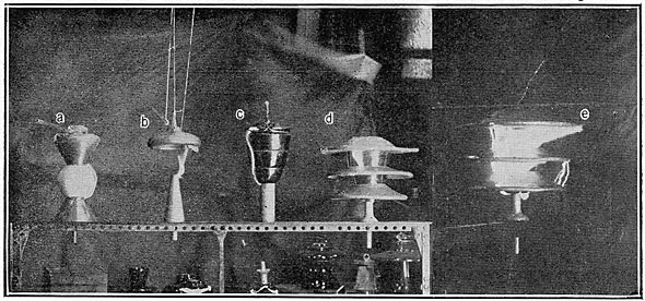
The dielectric fields of five theoretical designs were determined. Wherever a customary transmission cross-arm and line-wire are used, there are two principal planes of the dielectric field which show the greatest difference, i.e., the plane of the cross-arm and the plane of the line wire. These two planes are 90 degrees apart and in passing from one to the other the transition is gradual. During the investigation, records were taken of the dielectric field of these two principal planes and of a plane midway between the two. In this paper the diagram taken in one plane of the unit is usually shown. Diagrams of three planes of two designs are shown in order to illustrate the variations that occur. The plane in which the particular field was taken is indicated by the reduced top projection at the upper left portion of each figure.
DIELECTRIC FIELD FORMS AND ILLUSTRATIONS OF THEORETICAL DESIGNS
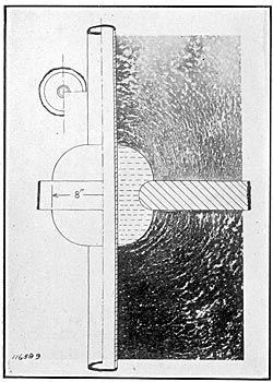
Fig. 1 shows the field form of a bushing having dimensions of ring and rod chosen such as to give maximum breakdown voltage over the surface for the mean diameter of torus ring.
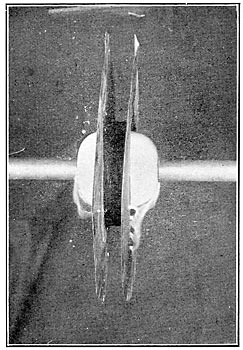
Fig. 2 shows a 60-cycle flashover on bushing of Fig. 1.
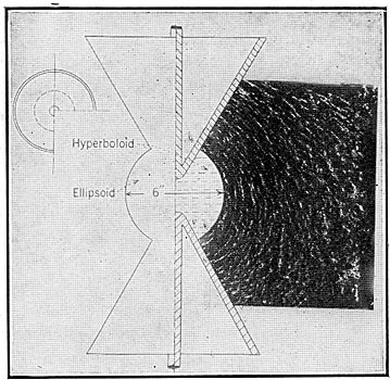
Fig. 3 gives the field form of a design using a confocal system of ellipsoids and hyperboloids of revolution.
Fig. 7A, 60-cycle flashover on shape shown in Fig. 3.
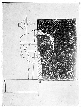
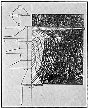
Fig. 4, field form between special metal cap and pin as might be used as terminals of a line insulator.
Fig. 7B, 60-cycle flashover between cap and pin as shown in Fig. 4.
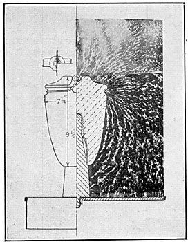
Fig. 5, field form of line insulator without rain sheds.
Fig. 7C, 60-cycle flashover on shape shown in Fig. 5.
Fig. 6, field form of pin-type insulator, the porcelain of which has a curvature similar to that of Fig. 5. However, the porcelain body is separated into three sections and metal rainsheds added to give wet arcing distance.
Fig. 7D, 60-cycle flashover on unit given in Fig. 6.
| |||
| Fig. 1 Dielectric Field About Theoretical Bushing |
| |||
| Fig. 2 60-Cycle Flashover Bushing of Fig. 1 |
| |||
| Fig. 3 Dielectric Field About Theoretical Design Using Con-Focal Surfaces of Resolution |
| |||
| Fig. 4 Dielectric Field Between Metal Cap and Pin |
| |||
| Fig. 5 Dielectric Field About Line Insulator Without Rain Sheds |
| |||
| Fig. 6 Dielectric Field About Insulator With Metal Rain Sheds |
| |||
| Fig. 7 60-Cycle Flashovers on Theoretical Porcelain Shapes |
In Table I are given the length of path over the insulator surface between electrodes and the 60-cycle flashover voltage.
|
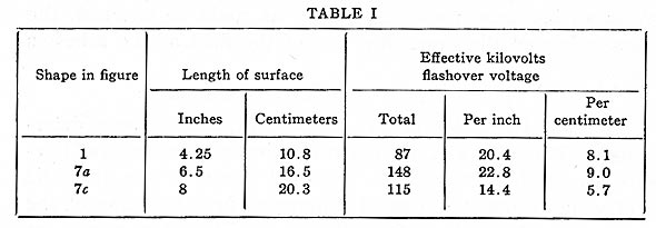
From a consideration of Table I it is evident that a flashover value of between 20 and 23 kilovolts per inch (8 and 9 kilovolts per centimeter) of surface may reasonably be expected if the unit is designed with contours of the surfaces approximating the flow lines of the dielectric field. Of course, the flashover on the unit without rain sheds is somewhat lower, being 14.4 kilovolts per inch. The lower flashover on this unit is due to two conditions, i.e., the porcelain surface does not follow the dielectric field in all planes and the small tie wire produces corona and subsequent static discharges at a relatively low voltage. Placing a static shield on the top of this unit increased the flashover voltage 18 per cent.
With the field form between cap and pin as given in Fig. 4, and the voltage values given above in Table I, theoretical insulator designs could be determined for such electrodes. Such designs should follow surfaces indicated on Fig. 4, as (a) and (b) . The highest flashover voltage for a given surface distance between electrodes would thereby be obtained. Moreover, the flashover voltage of such a unit could be closely approximated if the electrodes have sufficient radius of curvature at points of contact with the insulating material and a good seal is made between the metal and the insulating material.
MODIFICATIONS OF THEORETICAL DESIGN TO MEET OPERATING AND MANUFACTURING CONDITIONS
Insulators based on such theoretical data would be excellent from the electrical and mechanical standpoints if they were to operate in clean, dry air. However, the commercial insulator must maintain the transmission system during the heaviest of snow and rain storms. Moreover, it must have sufficient leakage distance to prevent flashover or even high power loss from surface leakage when the surface becomes dirty and wet.
The production of one-piece insulators for high-voltage service, although possible, would be costly. Also, the puncturing voltage of a one-piece unit would be low for a given thickness, since the stress in an insulating material between metal electrodes of different potential varies as a logarithmic function. The separation of the unit into parts that are cemented together, more uniformly distributes the stress of the dielectric if the unit is properly designed. It also decreases the probability of complete failure of the insulator and facilitates factory production, lessening the cost of the commercial unit.
The use of a special cap would be desirable from a dielectric standpoint. However, the voltage characteristics under rain are the same whether the usual line and tie wire or a special cap are used. Moreover, the cost and ease of replacement, cost of construction, etc., favor the line and tie wire construction.
PROPOSED COMMERCIAL INSULATOR DESIGN
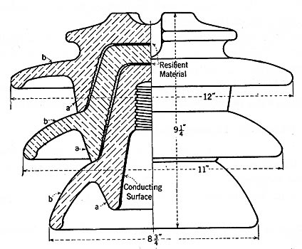
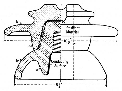
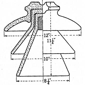
With the above limitations of the theoretical designs and the causes of insulator failures in mind, the type of unit indicated in Fig. 8 was evolved.
Summed up briefly this type of design embodies the following features:
1. Surfaces a conform to the flow lines of the electrostatic field.
2. Surfaces b of the rain sheds conform to the equipotential surfaces.
3. Lines of mechanical stress are parallel to the electrostatic flow lines.
4. The leakage resistance per shell is about equal, being increased gradually from the head to the center shell.
5. Approximately equal capacity per shell.
COMPARISON WITH OLDER DESIGNS
It is not possible to much more than indicate in the following discussion the methods employed to compare the proposed type of design given in Figs. 8A and 8B with the older commercial insulators. Samples of various commercial designs were produced and were subjected to rather thorough laboratory tests at the same time tests were made on insulators of the proposed design. It should be noted that the insulators of the new type used in the comparative tests do not exactly correspond to the proportions of Fig. 8. In order to lessen the cost of investigation, insulator sheds of several diameters were obtained from one set of molds by trimming the individual shells before burning. This also accounts for the unfinished appearance of the edges of sheds, etc., in some of the experimental designs.
|
|
In the following comparison it is not assumed that the evolved design should be final in each detail. The main goal toward which work is being directed is uniformity of all the elements entering into the designs with the idea in view of arriving at a type of design which will be equally successful in resisting failure in service whatever the requirements are in that particular section. In the following comparisons the items causing failure in service are discussed in the order given at the beginning of the paper.
1. Dielectric Field Distribution. The shortest air path under electrostatic stress should be at least long enough to prevent overstressing of the air at any point. In the theoretical discussions referred to in the introduction it was proved that wherever porcelain and air are in series in a dielectric field the voltage gradient per unit distance through the porcelain will be 1/4 to 1/5 the voltage gradient through the air. It is obvious that any thin section of air between porcelain sheds of a customary line insulator will be over-stressed even at the normal line voltage of the insulator.
In order to make a comparison of the dielectric fields of various insulators, their field forms were determined as in the investigation of the theoretical designs. It is believed that the following field forms and illustrations sufficiently indicate that many present types have not been designed with a full appreciation of the advantages of shapes that conform to the electrostatic flow lines in obtaining the most efficient distribution of the stresses in the dielectric field.
Fig. 9 (insulator C) gives the dielectric field of a unit of the type used in the early developments of high-voltage trans? mission. The air between sheds just below the cement section is highly stressed. Because of the height of the pin in proportion to other dimensions of the unit the stress toward the base of the pin and the supporting cross arm is very low. Moreover, the third shell of the insulator is spaced so close to the insulator pin that it does not take its proportion of voltage stress when either dry or wet flashover occurs.
Fig. 10 (insulator D) shows the dielectric field of a three-piece insulator of a somewhat more recent design. The center shed is better spaced than in insulator C. However, the air just below the cement sections is highly stressed and the short rain shed of the second shell gives an unequal voltage distribution at flashover, dry or wet.
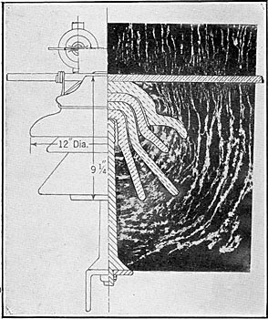
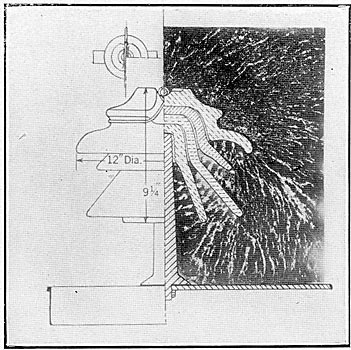
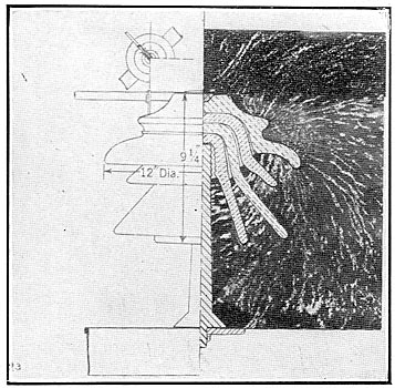
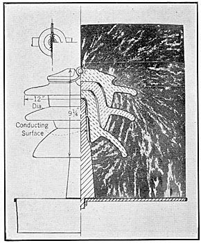
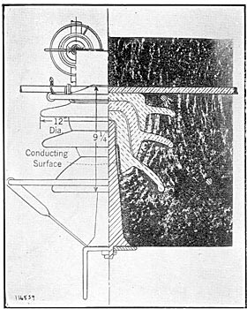
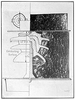
Figs. 11, 12 and 13 (insulator E) show the dielectric field of a four-piece unit of comparatively recent design. The sheds of this design are more uniformly spaced, but the air between sheds just below the cement sections is highly stressed. The stress throughout the dielectric field of this unit is an improvement over the types C and D. However, the short second shed and protected fourth shed give unequal voltage distribution at flashover dry or wet.
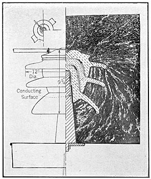
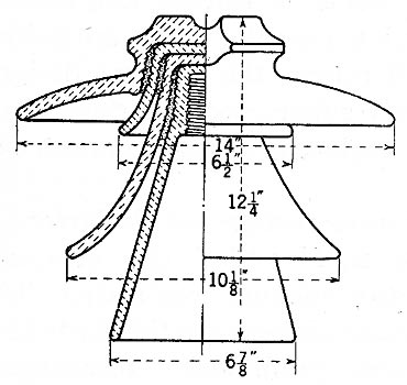
Figs. 14, 15 and 16 (insulator F) show the dielectric field of a unit of the proposed design. The shortest air path between shells is sufficient so that the air is not overstressed at working voltage of the insulator or until flashover occurs. Moreover, the rain sheds are so spaced that each section of the unit takes its share of the stress at flashover, dry or wet.
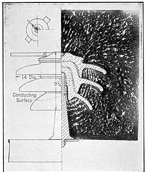
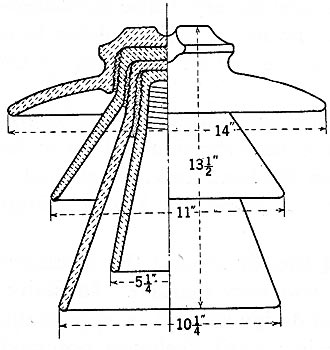
Fig. 17 (insulator G) shows the dielectric field of a unit similar to insulator F, but having rain sheds of greater diameter. The diameter of the head of this unit is probably out of proportion and greater than would be most satisfactory for service. However, the stress in the dielectric is well proportioned and the voltage distribution per shell at flashover, dry or wet, is fairly well proportioned.
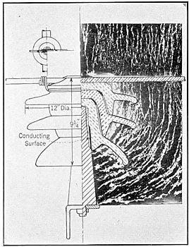
Fig. 18 (insulator F) shows the dielectric field of the insulator having upper surfaces of the rain sheds covered with a conducting paint. This field form which approximates the rain conditions indicates that the stress per shell on the unit during rain would be approximately equal. Moreover it indicates that the stress in the dielectric field is more uniform during rain.
Fig. 19 (insulator F) shows the dielectric field of the insulator when equipped with Nicholson Arcing Rings, and indicates that the most highly stressed portion of the field about the insulator is not changed. However, the most highly stressed portion of the field between the line wire and cross arm is now between arcing rings and flashovers would, therefore, occur between rings.
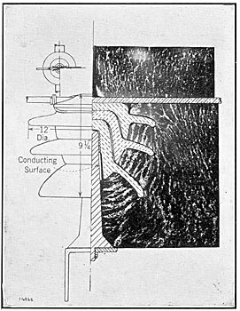
Fig. 20 (insulator F) shows the dielectric field when static shields are placed at the top and base of the insulator. This combination would give a very fine distribution of stresses in the dielectric but would be rather expensive commercially.
| |||
| Fig. 9 Insulator C Dielectric Field About Line Insulator of Early Design |
| |||
| Fig. 10 Insulator D Dielectric Field of Insulator of Fairly Recent Design |
| |||
| Fig. 11 Insulator E Dielectric Field About Insulator of Recent Design |
| |||
| Fig. 12 (See Fig. 11) |
| |||
| Fig. 13 (See Fig. 11) |
| |||
| Fig. 14 Insulator F Dielectric Field About Insulator of Proposed Design |
| |||
| Fig. 15 (See Fig. 14) |
| |||
| Fig. 16 (See Fig. 14) |
| |||
| Fig. 17 Insulator G Dielectric Field About Insulator of Proposed Design |
| |||
| Fig. 18 Insulator F Dielectric Field About Insulator of Proposed Design Under Conditions Approximating Rain |
| |||
| Fig. 19 Insulator F Dielectric Field About Insulator of Proposed Design Installed With Nicholson Arcing Rinds |
| |||
| Fig. 20 Insulator F Dielectric Field About Insulator Having Static Shields at Top and Base |
60-CYCLE FLASHOVER TESTS
Flashover on most of the older insulator types is caused by the corona formation at the line and tie wires and the edges of the cement joints between shells. As the voltage applied to the insulator is increased, the area of the corona formation increases and static streamers gradually spread over the surface of the insulator sheds. The static streamers increase in length until the air insulation between them finally fails and flashover follows. Obviously, the path of the flashover will start along the path of these streamers and thus trouble may be caused by the intense heat of the power arc and rain sheds may be stripped from the insulator.
| |||
| Fig. 21a Insulator I |
| |||
| Fig. 21b Insulator K |
| |||
| Fig. 21c Insulator H |
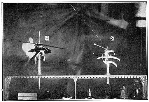
In the proposed type of design there are no static streamers from the edges of the cement section between shells up to flash-over voltage. The corona formation at the tie and line wires therefore, builds up until flashover occurs by breaking down an air path between the line and pin or cross arm. The proof of these statements may be seen in the following illustrations. The axes of the two units in each of the following figures giving comparative flashovers were at the same distance from the camera lens and hence the dimensions are directly comparable.
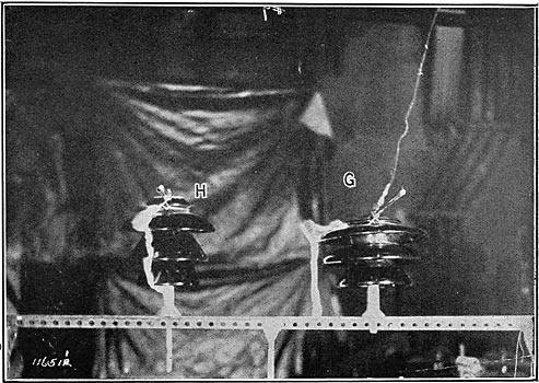
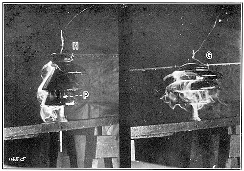
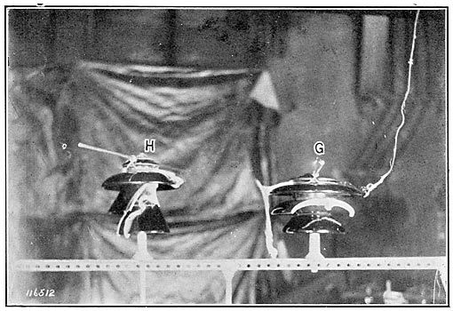
Figs. 22 and 23 show illustrations of dry and wet flashovers respectively, on insulators G and H. The design of insulator H is given in Fig. 21c.
| |||
| Fig. 22 60-Cycle Dry Flashover |
| |||
| Fig. 23 60-Cycle Wet Flashover |
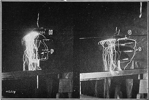
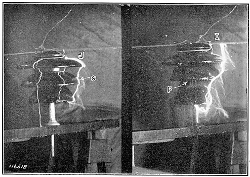
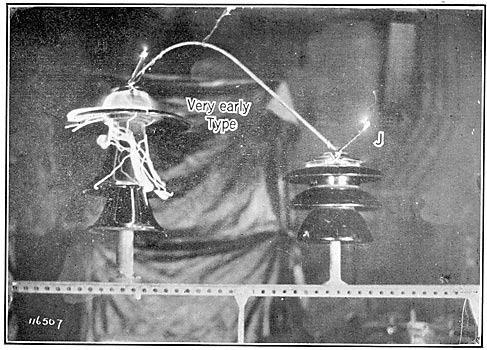
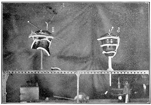
Fig. 24 shows an illustration of wet flashover on insulators J and I. The design of insulator I is given in Fig. 21A. Insulator J is of the proposed type similar to the unit given in Fig. 8.
Fig. 25 illustrates of one of the early types of high-voltage insulators and insulator J in parallel. The finer lines over the surface of the old type unit are preliminary static discharges. The final power arc passes from the left of the insulator head around in front of and finally to the pin at the back of the insulator.
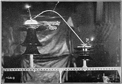
Fig. 26 shows insulator F in parallel with the unit of early design shown in Fig. 25, and shows the corona formation and static discharge over the head and between the head and second shell of the old type unit. The camera exposure was 3/4 of a minute at F-8.
| |||
| Fig. 24 60-Cycle Wet Flashover |
| |||
| Fig. 25 60-Cycle Dry Flashover |
| |||
| Fig. 26 60-Cycle Test Comparative Corona Formation |
The difference in the stress in the air around the insulators just below flashover voltage dry was very marked. Insulators F, G and J of the proposed type of design showed no appreciable corona except at line and tie wires until flashover occurred. Flashover occurred from tie wire or line wire to pin or cross arm, there being no tendency for the arc to start between the rain sheds. Considerable corona formation and static streamers could be detected on insulators E, H and I. Static streamers began to spread out over the surfaces between shells of insulators H and I at 80 per cent of flashover voltage, and unless these units are mounted on rather low pins the power arc holds close to the insulator surfaces. Of course, the old type design of Figs. 25 and 26 has been entirely superseded but these two figures clearly indicate the entire neglect of a consideration of the dielectric field.
The difference of distribution of stress before wet flashover is even more noticable. In insulator E, H and I the unequal spacing of rain sheds and consequent unequal wet arcing distances, combined with a highly stressed air between the sheds below the cement sections produces preliminary discharges (marked p) between rain sheds. These preliminary discharges throw electrical impacts onto parts of the insulator and short-circuit portions of the porcelain between the line and pin. Consequently, when a line surge occurs during a rain storm or when the unit is wet and dirty the factor of safety of these insulators in resisting puncture or flashover is actually no more, and sometimes is less, than it would be minus one of the shells.
Insulators F, G and J of the proposed design show no preliminary discharges except static from tie or line wires to pin or cross arm. Static discharges (marked s) are shown on each of these units. All of the leakage surface and thickness of porcelain between line and pin are, therefore, effective up to failure by flashover.
2Surface Leakage: As previously stated, the leakage surface of many of the older designs gives a very uneven voltage distribution per shell. Table II gives the resistance per shell of various insulators tested during this investigation. The values were obtained by an integration of the surface, i.e., surface resistance equals
|
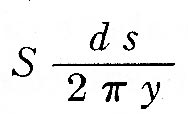
where d s is an element of surface and y the radius of that element from the axis of the insulator.
It is obvious from this table that certain of the older designs, especially those having a short second shell, long inner shells, etc., have a very unequal surface resistance per shell. If the insulator surface becomes dirty and wet so as to pass a leakage current of even a thousandth of an ampere the voltage distribution would depend upon this current and the capacity current could be neglected. The voltage gradient over the insulator surface thus often becomes sufficient to cause discharge between sheds and pin or cross arm or over the short sheds. An electrical impact is thereby applied to parts of the insulator and portions of the porcelain body between line and pin are short-circuited. It is believed that the continued overstressing of parts has been the cause of many insulator failures in the past.
|
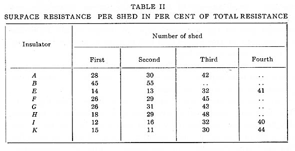
The surface resistance of the proposed designs as typified by insulators A and B in Table II is gradually increased from the top to center shells, the increase being considered as an advantage since the center sheds will usually become dirtiest.
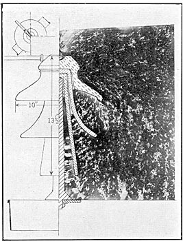
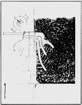
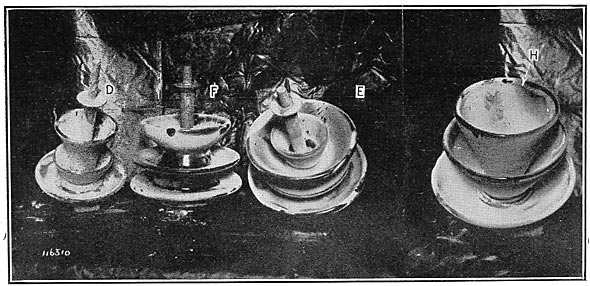
A novel feature of the proposed design is illustrated in Fig. 27 showing insulators D, E, F and H. These units were set on a cross-arm line, and tie wire attached as in service, voltage applied and plaster of paris dust blown around them. The surfaces along the lines a of the proposed design (Fig. 8) are practically free of dust.
| |||
| Fig. 27 Plaster Paris Dust Deposited With Insulators Under 60-Cycle Voltage |
| |||
| Fig. 28 Top Shed Broken 60-Cycle Wet Flashover |
| |||
| Fig. 29 Second Shed Broken 60-Cycle Dry Flashover |
| |||
| Fig. 30 Second Shed Broken 60-Cycle Wet Flashover |
| |||
| Fig. 31 Second and Third Shed Broken 60-Cycle Dry Flashover |
| |||
| Fig. 32 All Sheds Broken 60-Cycle Dry Flashover |
The reason for this is quite apparent. All the force acting in the dielectric field along this surface a is tangential and would tend to force the particles to the sheds above or below. The same action was noted when the units were subjected to atomized salt water. This feature would doubtless have some value in dust laden sections since the dust would tend to settle mostly on the lower shed and rain and wind would clean this to some extent.
It is necessary to clean the insulators in long portions of line in certain sections of country as the coast districts of California. It is very apparent that the proposed type of design may be cleaned much more readily and thoroughly than any of the older types.
3. Porosity. As denoted previously, the porosity of porcelain is a specific problem of the ceramic engineer rather than the designer. As clearly pointed out in a recent paper' by Prof. Ryan we apparently have no method of detecting the very slightly porous material which may cause trouble. Since porosity is a function of the body composition, manufacturing process and burning, even with the most careful production and testing, a small amount of this slightly porous material is not detected. The thicker portions of the porcelain in the cemented area of the proposed type of design should minimize the number of the pieces that will give trouble later in service.
4. Mechanical Breakage.
(a) From Handling: The increase of thickness of the rain sheds and addition of a drip edge will materially decrease the percentage loss from this cause.
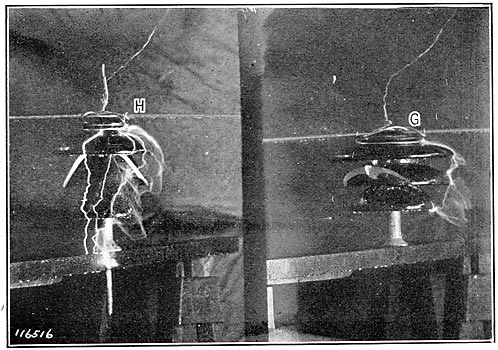
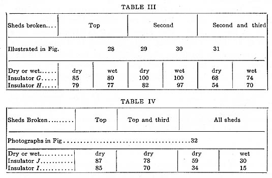
(b) Mischievous Stone Throwing and Rifle Shooting: (1) The following photographs give comparative flashover voltages dry and wet, on units having various rain sheds broken by throwing a small weight at the insulator. Figs. 22 and 23 show the dry and wet flashovers on insulators G and H respectively. Table III gives the flashover voltages of broken units in per cent of flashover of the unit when unbroken. Reference to illustrations is made in the Table. Fig. 24 shows the wet flashover on units J and I. Table IV gives comparative flashovers of broken units, as in Table III.
|
As would be expected from a study of the dielectric field diagrams, the breaking of the second shed of the proposed type of design has practically no effect upon the flashover values of the insulator. In fact, as shown in the illustrations, the paths of the dry and wet flashovers did not follow over the broken shed. When sheds are broken, the corona formation and static streamers build out over the surface of the older type of design at a lower voltage than when the units are intact. The paths of flashover over these older types, therefore, follow the surface of the insulator. In the proposed type of design the absence of streamers from the porcelain surface causes the arc to keep clear of the insulator. A power arc will, therefore, be less liable to cause complete failure of a broken unit of the proposed design.
One of the most important features of the proposed design is that when the units are hit by stones, etc., the rain sheds will not crack or break beyond line a Fig. 8, due to the shape of the individual parts. The rain sheds of the older types of designs when hit are very likely to crack or break up into the cemented section. The first voltage surge or even normal line voltage will, therefore, often puncture the remaining shells. In fact, in the two series of tests photographed, both the older type of units punctured during the dry arcover after sheds were broken. Static streamers shot over surface of insulator H in Fig. 31 and then puncture occurred. Insulator I, Fig. 32, flashed over and then punctured before the circuit breaker of the testing transformer operated.
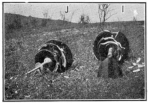
(2) One each of units H, I and K and two of J were subjected to rifle shots. Twenty-two caliber long bullets were shot at the insulators from about 30 yards distance and in a line at 45 deg. to their axes. The following photographs show the comparative breakage and the ability of the broken units to thereafter withstand electrical test. The shooting was done by men disinterested in the design of the insulators and they were requested to do as much damage as possible.
| |||
| Fig. 33 After 15 Shots Were Fired at Each |
| |||
| Fig. 34 After Number of Shots As Indicated |
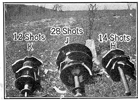
Fig. 33 shows insulators I and J after 15 shots were fired at each. The top, second and third shells of I were broken, the second shell being cracked into the cemented section. The second shell of J was chipped in two places, the rest of the insulator being intact. Fig. 34 shows insulators H, K and I after 14 shots were fired at H, 12 at K and 28 at I. The second and center shells of H were cracked and the center of K. The sheds of J were chipped off in a few places but the shells were not cracked. These five units were then set with their axes at right angles to the line of fire. Not more than 5 or 10 shots were necessary to strip the main part of the remaining sheds from Insulators H, K and I while one unit of type J still retained a considerable portion of its sheds after approximately 100 shots had been fired at it. The sheds remaining on the two units J were then knocked off by a hammer, to illustrate to those present that the surface of the insulator that follows flow line a would not be cracked thereby.
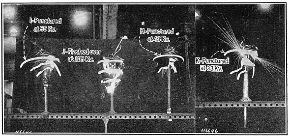
Fig. 35 shows the first dry flashover test made on these units after the shooting. Units H, K and I punctured at voltage of 33, 43 and 56 kilovolts, respectively. Unit J flashed over at 105 kilovolts, the remaining porcelain body bounded by line a still being intact.
| |||
| Fig. 34 60-Cycle Dry Flashovers on Insulators H, I and J After Breakage From Rifle Shots |
| |||
| Fig. 35 Resistance to Side-Pull |
(C) Insufficient Strength as a Support: Two samples as per Fig. 36, were tested to determine the resistance to side pull. In each case load was applied at the wire groove which was one foot from the base of pin. The parts from which insulator L was formed were obtained by trimming off the rain sheds of individual shells of unit J before burning and the mechanical test should, therefore, be about the same as of unit J. The pin of unit L was cemented directly into the insulator. A separable pressed steel thimble was cemented into insulator F. The one-inch bolt of the pin cemented into insulator L failed at 4400 ft-lb., and 3100 ft-lb. bent the pin of insulator F as shown, the position of insulator being such that additional load could not be applied. Both units were electrically intact after these tests.
(d) Brittle Material. All units used in these comparative tests were made of the same porcelain body and hence the question of brittleness, which is a ceramic problem, does not enter.
(5) Lightning. The impulse ratio of the proposed design is lower than that of most of the older types of design. The actual value has not been determined. This statement is based on tests of the proposed design in parallel with older types. The old types of design were set on a pin of such height above the cross arm as to cause the old type of unit to flash over when set up alone at a voltage slightly greater than that of the proposed type of design alone. When tested in parallel the static discharges over the porcelain surface of the older type would often cause the proposed type to flashover first.
Furthermore, the body of the porcelain bounded by the flow lines a should have an impulse ratio close to one. A very high impulse voltage might, therefore, puncture through the rain sheds of the insulator leaving this body of the unit intact. The thicker section of porcelain between line and pin will also materially increase the factor of safety of the unit.
(6) Unequal Expanion of Metal, Cement and Porcelain. The introduction of a resilient material between tops of shells should eliminate the tendency of certain older designs to split off. Greater radii of curvature at the tops of the insulator shells and a cement section sloped from the axis should tend to eliminate the trouble from any difference of coefficient of expansion of the porcelain and cement.
(7) Internal Stresses in the Material. Internal stresses set up in the insulator parts during manufacture should be very much decreased by the elimination of small radii in corners and sudden changes of cross section of the material.
CONCLUSIONS
Briefly stated, it is believed that the advantages of the proposed type over the older commercial types in resisting failure in service would be as follows:
1. When the insulator is dry, the corona and static formations are practically limited to the tie wire and line wire up to flashover voltage.
2. When the insulator is wet, no corona or static formation occurs up to flashover voltage. The flashover voltages for given overall dimensions are thereby increased.
3. The leakage resistance per shell is increased gradually from the head to the center shell. This takes into account the probability of the lower sheds becoming dirtier than the tops. The voltage distribution per shell is, therefore, equal when the insulator becomes dirty and wet and a heavy leakage current passes over the insulator.
4. Since the capacity per shell is about equal, the voltage distribution per shell will be equal when the insulator is clean and in dry air.
5. Since the distribution of voltage per shell depends upon the capacity current and leakage current, the distribution of voltage per shell in these designs should be approximately equal under all operating conditions.
6. The resistance of the insulator to side pull for a given weight and given electrical strength is relatively high. This is due to the feature of the design whereby the flow line a of the electrostatic field and the mechanical stress lines coincide.
7. The design of the individual shells is such that when they are tested before assembly the surface conforms to the electrostatic flow lines a. This allows testing of the individual parts to a higher percentage of service voltage than was possible in case of the individual shells of older designs.
8. Due to the shape of individual parts and of the assembled unit, the insulator sheds when hit by stones, riffle, balls, etc., do not break beyond surface a. The unit, therefore, offers a considerable percentage of its original resistance to flashover after the sheds are broken. The same feature tends to protect the insulator from complete failure during flashover in service.
9. Each characteristic of the insulator which would vitally affect durability in service has been treated uniformly throughout the line.
DISCUSSION ON "APPLICATION OF THEORY AND PRACTISE TO THE DESIGN OF TRANSMISSION LINE INSULATORS" (GILCHREST), ATLANTIC CITY, N. J., JUNE 26, 1918.
Charles Fortescue: The primary facts to be dealt with in the application of electricity, the two main things, are conduction and insulation. These two facts involve other elements which should be termed the electric circuit, the dielectric circuit and the magnetic circuit. The former and the latter have been given a great deal of attention, but not much attention has been given to the dielectric circuit.
There are two reasons for this. One reason is that in the early days the methods of insulation for low voltages were so obvious that there was not much necessity for giving the dielectric circuit much consideration. Latterly, however, as the conduction problem became more difficult it was necessary to increase the voltages used, and, therefore, for that reason the dielectric circuit became of increasingly greater importance. The problems involved in the dielectric circuit are in three dimensions. They are not easy of solution. They involve some of the most difficult mathematics that are known. Therefore, it is essential to find some practical method of dealing with these problems, and some of these methods have been outlined in various reports from time to time. Mr. Farnsworth and myself brought out a method of plotting out the equipotential surfaces by using an electrolyte. Mr. Rice in a paper a short while ago also mentioned some methods, in fact, he took our method and improved upon it very materially.
Mr. Gilchrest has made use of some of these methods and other methods evolved by other people to produce a practical insulator.
In a paper presented to the Institute some years ago I brought forward an apparent paradox, namely, that by the use of conductors the effectiveness of an insulator can be increased. There is real truth in this. To insulate a body or system of bodies, it is necessary not only to consider the insulating body, but we must also consider the shapes of the bodies to be insulated. We must so form these bodies that they may be insulated with the maximum effectiveness.
In the large porcelain insulator problem, we have to insulate a line wire, we will say, from a cross arm, and we have to evolve an efficient form of insulator, and consider what form of conducting surface will be best suited under the various conditions; that is to say, when it is raining, or when the surfaces are dirty, etc., and this brings up another point, and that is the question of what is meant by theory and practise.
The term "theory" is being used rather loosely to cover an approximate solution of a problem, taking into account what are considered the most important factors. Strictly speaking, theory should account for all the facts, as we know them, and as we observe other facts they are to be introduced into the theory. There are many ways of doing this. One way is to make as close an approximation as possible with known theory and then find out how much it is necessary to deviate from this approximation in order to take account of, or care for, other considerations that come from actual practical work.
Now, in this insulator of Mr. Gilchrest's, we have to consider, as I said before, the best form for the insulating body and conductors and we must take into account the fact that certain surfaces attract dirt, or dirt under certain conditions tends to accumulate upon them. The problem is to produce something in which the distribution of stress will be affected as little as possible by changes in the external conditions. The working surfaces, properly speaking, should conform to the flow lines, or the Faraday tubes. There is a very good reason for this. One is, it cuts down the actual intensity at the surfaces of the insulator. You do not have as much ionization. Another reason is, since the intensity is parallel to the surface, it is preventive of the accumulation of dirt on the actual working surfaces. On the other hand, if, instead of conforming to the flow lines, the boundary surfaces are at right angles to the flow lines, even if they get dirty, they will have the effect of equipotential surfaces, just the same as if we extended the internal equipotential surfaces out into the air. As we know, if a conducting surface coinciding with an equipotential surface is not very thick, it has almost no influence on the shape of the Faraday tubes.
There are other considerations, such as the proper proportioning of the capacity of each part of the insulator, etc., the theory of which has been presented in papers before the Institute. These have all been taken into account in the design of this insulator and have been dealt with in this paper.
There is a common belief that there are two ways of looking at these matters, the theoretical way and the practical way. I wish to emphasize the fact that there should not be, that there should be only one way to consider them, and that without casting any reflections upon practical experience, might be termed the theoretical way. In other words, the theoretical way should account for all that practical experience shows. There is a school which takes the stand that in designing insulators practical experience alone counts; in other words, we are expected to arrive at an efficient design of an insulator by a process of evolution or the survival of the fittest. I think that such a process of arriving at a design is rather hard on the people who have to bear the brunt of being the innocent victims of the experimentors. In a few words, I think a proper consideration of all the facts involved ought to enable one to arrive at a good design, which shall be theoretically correct, and this means, also, that the insulators should stand up in practise, and I believe that the work which Mr. Gilchrest has done is a big step in this direction.
Charles F. Scott: When a new device is described, we do not get the full significance of it unless we get it in historial perspective. An interesting chapter in insulator history was furnished by the International Electrical Congress, held in 1904 in connection with the Exposition at St. Louis. The Transmission Section brought together the transmission engineers from the Pacific Coast and from the Rocky Mountains, as well as from the East. They were the actual, practical operating men, who came together to interchange experiences and to learn what they could.
The foremost problem in several days of papers and discussions was the insulator. Voltages had risen to 50,000 volts, 60,000 volts, and I think 66,000 volts. They had been of that order for a number of years and no advances had been made. Transformers of double ratio had been installed for 88,000 volts and a lower voltage, but the high voltage was not used because no suitable insulator had appeared.
These paperssome of them specifically on insulators and insulator design, and many of them with regard to operating conditionstell of insulator troubles, and in discussing the future use of higher voltages, the insulator was the one thing which seemed to set the limit. The pin form of insulator was the only one considered. These apprehensions have been justified by subsequent history, as no plants are operating in this country at any substantially higher voltages with pin insulators than there were at that time. There was no suggestion offered, as I recall now, except some modification of a pin-type insulator, which it was proposed to be make larger and larger, until one engineer suggested that it would resemble a Chinese pagoda in size. There was a limit. The solution came, and the method of operating at higher voltages was worked out by leaving that type of insulator and going to something else, the suspension insulator.
Mr. Gerry, of the Missouri River Power Company, read a paper at this Congress, in which he discussed the insulator, and described a number of elementary experiments to show that the electrostatic field has a good deal to do with the character of the discharge on insulator surfaces, and said that these elements must be considered in insulator design. Dr. Perrine, one of the leading engineers of that time, both in practical experience in one of the largest transmission plants in the West, and also because of his well known theoretical knowledge, said that Mr. Gerry had put his finger on the point to which attention must be given in the future, as we had neglected the electrostatic element in insulator design. The Institute TRANSACTIONS of the past fourteen years since the Electrical Congress contain, almost annually, papers describing the difficulties and troubles with insulators in one way or another, which have been epitomized very well at the beginning of the paper presented today. One must have all these difficulties in mind to appreciate this paper, which runs along so beautifully, showing how theory has been applied to practise and the two together have produced something that looks so simple and obvious, that it almost makes us feel that there is nothing striking about it. A new step has been taken in the evolution of the insulator. There have been scores of different types, many of which follow some one idea, but have carried it to an extreme and violated some other principle.
The paper shows very nicely, as Mr. Fortescue pointed out, that as long as we deal with the electric circuit alone we get along very well until we get up into the region of high voltage, and then the electrostatic field comes in; at first its importance was not recognized, but now it has been recognized, and this new solution results.
This paper indicates how admirably the subject has been handled from the standpoint of research and experimental development.
The great value of the paper, then, comes in this notable step in design which leads to a more simple and practicable and desirable form, in a field in which insulators by the thousand, yes, by the million, are in use, and it becomes, therefore, of the highest importance in adding to the safety and reliability of high-tension transmission.
Another point that has not been brought up, which is one of interest and consequence, is this,if this insulator is so much better for the field which has been occupied by pin-type insulators on the order of 66,000 volts, may not this new design enable transmission lines of still higher voltage to use the pin type of insulator advantageously?
V. Karapetoff: One point that is not brought out in Mr. Gilchrest's paper is the question of refraction of lines of force when they pass from the dielectric of one permittivity K1 into a dielectric having a different value of permittivity, K2. The lines of electric force experience a refraction similar to the refraction of the magnetic lines of force when they pass at an angle from a ferrous material into the air. This refraction is different from that of rays of light, in that the law which holds here is that of tangents and not of sines.
A college girl in her examination paper, which had the question, "State briefly the law of refraction of light." wrote "The sins of the angels are constant." Well, here it is the ratio of the tangents that is constant.
If the angle of incidence is Omega1 and the angle of refraction Omega2, then the law of refraction is
|

For a proof of this law see for example, V. Karapetoff's "Electric Circuit," p. 163 (second edition.) I mention this fact, because it is not mentioned in the paper, yet the field is being studied there outside the insulator, and not within the insulator, while we are primarily concerned with the dielectric stresses within the insulator.
It should not be assumed that by mentally extending the lines
·
·
[Missing text]
·
·
