[Trade Journal]
Publication: Electrical World
New York, NY, United States
vol. 80, no. 20, p. 1042-1044, col. 1-2
Transmission-Line Construction in Japan
As One Result of the Rapid Development of Water Power the
Art of Transmission Has Become Highly SpecializedThirteen
Lines, Four Carrying 154,000 Volts, Will Serve Tokyo and Osaka
By ERNEST V. PANNELL
Engineer British Aluminum Company, New York
PROBABLY no country in the world is converting potential water power into electrical energy at so great a rate as Japan. Water power rights are vested in the state, and the various prefectures have authority amounting to a veto at the discretion of the governor; nevertheless these facts have not acted as a hindrance to the free and logical development of natural resources. As an illustration, one large power company supplying the city of Osaka is already operating four plants producing 40,000 hp. and is developing nine other sites which will yield 250,000 hp. additional, most of these sites being now under construction and scheduled for operation within the next two years. This system is one typical of at least half a dozen power networks in a similar state of development.
In general the watershed which forms the Sierras of Japan lies along the northern shore of the island and the industrial cities are on the south. Chief among the latter are Tokyo (population 2,500,000) and Osaka (population 1,500,000). Power developed in the mountains is therefore carried across the central plain in a southerly direction to the seaports and the centers of industry, and the transmission-line art has been highly developed. The following are the principal systems operating high-tension transmission lines to supply the two principal cities:
|
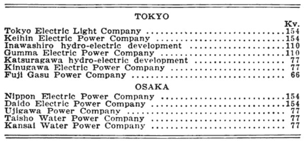
The four 154-kv. lines mentioned above are now under construction, together with a power line of similar voltage in the island of Formosa, this figure of 154 kv. having been adopted as a standard. Transmission distance for the longest lines does not generally exceed 150 miles, but, with the present tendency to interconnection, a great number of power sources and receiving points are tied into a network so that the average distance of transmission is reduced. Any group of public utility corporations may be compelled to merge where it is in the interest of the general public, the decision in such a case being given by the Department of Communications. This is a federal department of considerable authority and also of considerable utility because it is concerned with railroads, telephones and telegraphs and also with power transmission. The department can therefore co-ordinate conflicting interests in such matters as telephone interference and crossing construction; indeed, the first-mentioned consideration has been responsible for the wide use of delta high-tension connections or, alternatively, of a relatively high resistance in the ground connection of a Y system.
In addition to the groups of systems above mentioned, extensive power networks are in operation or under construction in the islands of Kiushiu, Shikoku and Formosa. The Shikoku power centers are expected to be tied in with a 400-mile superpower network linking Osaka with Moji and there connecting with the Kiushiu systems. In the near future also a very extensive power development on the Shinano River will be made by the Imperial Japanese Railways, now in course of being electrified. This will involve transmission at 154 kv. and at lower voltages also.
GOVERNMENT SUPERVISION EXISTS
Pole and tower line design is based upon the recommendations of the Department of Communications not only as regards crossings but in relation to the entire line, whether on private right-of-way or not, and all designs have to be submitted to the department as well as to the local prefecture for approval. The loading assumptions are of two kinds, depending upon whether or not the district is subject to sleet: (a) Wind load of 20 lb. per square foot on projected area of wire, no sleet; (b) wind load of 10 lb. per square foot on projected area of wire, 1 in. sleet.
In districts where sleet does not prevail it is seen that a higher wind load is calculated upon. For the conductors a maximum stress of one-half the ultimate figure is allowed, with the following minimum specifications for tensile strength:
|
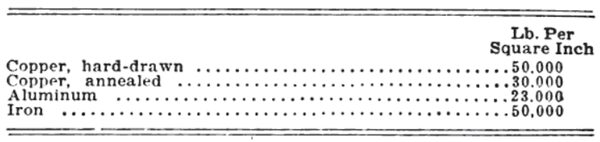
Steel-cored aluminum is being extensively used on practically all the new power lines, especially in the mountain districts where the corona disruptive voltage is low. The tensile strength of this material varies with the make-up of the cable from 40,000 lb. to 50,000 lb. per square inch. Investigation is now being made by the department with a view to establishing its properties. There is a tendency not to string aluminum-steel conductors as tightly as copper because a small sag can be realized with a lower tension and tower steel can be saved. At the same time there are many long river crossings where it is desirable to work up to 50 per cent of the ultimate tensile strength of the cable.
Wooden-pole lines are extensively used, the most typical construction consisting of two poles braced together with steel channel cross-arms and three pin-type insulators for a single 77,000-volt circuit. The spans are from 300 ft. to 400 ft. and the poles are guyed at angles. A special design for crossings is required by the Department of Communications. In this case there are two insulators for each wire. A short additional length of cable is tied to the extra insulator and securely joined to the main cable on each side of the pole about 3 ft. out. In this way if an insulator flashes over and the wire is burned off, it cannot fall in the road, because the other insulator will hold it. The same construction is used both for highways and railroad crossings. For wooden poles the design loading calls for a wind pressure of 24 lb. per square foot of projected surface at right angles to the line, with a safety factor of five on the pole.
Present construction is of steel in nearly every case, and for 110 kv. and more suspension insulators are used, but there is a strong tendency to perpetuate the use of pin-type insulators for line voltages up to 77,000. Tower steel is fabricated in Japan, but a number of orders are placed with American concerns because in most cases their designs are better. In Japan the shops are not laid out especially for tower work, but for general structural designs; consequently they are not equipped with the templates and shearing and punching machinery for the many small members required in a transmission tower. For the same reason Japanese towers use a number of gusset plates and what would be considered in America unnecessary members. The subject of transmission-tower design is being very carefully studied in Japan, and a series of experimental tests on full-size designs is being carried out at the Kyoto Imperial University under the supervision of Prof. E. Aoyagi.
Insulators are made in Japan by the Nippon Insulator Company, at Nagoya, the historic center of the porcelain industry, and by the Shofu Insulator Company at Kyoto. Both of these companies produce the metal-cap form of suspension unit in addition to the large pin-type units for 66 kv. and 77 kv. Most units are of white finish, as it is believed to be easier to locate a defective insulator by its discoloration. A large number of insulators are imported from America, and it is a common thing to see American and Japanese insulators hung on different circuits on the same tower. No grading shields have yet been employed, but experiments have been made with a ring-shaped device, and it will probably be used on one of the 154-kv. lines now being built. Insulator hardware is made in Japan, but there is a certain amount of dissatisfaction resulting from the use of malleable iron fittings, and Japanese shops are not as yet equipped for drop-forging these products. The climate of Japan is for the most part very moist, and galvanizing has therefore a very short life. In many parts of the country it would be better to paint the towers and fittings, because the rapid deterioration constitutes a distinct hazard.
| |||
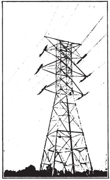
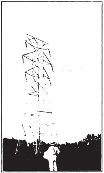
| Steel Towers Are Guyed to Withstand Abnormal Storm Conditions on the Lines of the Tokyo Electric Light Company. |
| |||
| A Tower for A 6-Deg. Horizontal Angle on the Line of the Inawashiro Power Company Has 50-Lb. Balancing Weights. |
| |||
| Anchor Towers Are Used Extensively on the Lines of the Inawashiro Power Company |
One feature of the line design used is well known to all engineers who have been concerned with construction in mountain districts. The steep profiles necessitate in places towers at widely different elevations involving a "pull-up" at the lower suspension point. "Tie-down" insulator strings have been used on the lower tower at such locations, but the usual troubles have been experienced with flashing over and rapid deterioration of the lower insulator, so that the tendency now is to use weights at such a point, in this way maintaining the flexible characteristics of a suspension insulator line. The same procedure has been adopted where a suspension tower is used for small deviations from alignment to prevent the insulator swinging in and grounding the wire on the tower frame. Indeed, in one case weights are now in use after the towers have been modified by the addition of an extra bracket for us- with tie-down insulators.
Construction work in the field is influenced by the fact that for the most part the terrain is swamp or mountain. For this reason and because the standard of proficiency is very low among the laborers towers are built up from the ground piecemeal, three men being able to complete a 4,000-lb. tower in a ten-hour day if the conditions are good. The stubs are, of course, set first, generally in concrete. Most of the tower lines run across the paddy fields, which are in a semi-liquid condition during most of the year, and this condition, together with the frequent earthquakes, has been responsible for the subsidence of foundations on some of the older tower lines. This has been corrected by guying in several places to patent anchors driven deep enough to reach solid ground. In some more serious cases the tower members have been braced with timber as a reinforcement against distortion.
SOME TOWERS ASSEMBLED ON GROUND AND HOISTED INTO PLACE
In a few isolated cases towers have been assembled on the ground and afterward hoisted into place. Owing to the difficulty of using a team or a truck, a capstan has been set up and the fall of the lifting tackle connected to it. Then a dozen men have taken the capstan bars and raised the tower to the sound of the invariable chanty. A windlass has been used for wire stringing, but the result has not been so satisfactory, and it is more usual to strain up entirely by manual tension with the usual tackle and dynamometer. As a field crew consists of at least twenty-five to thirty men, there is plenty of power available of an unskilled type and at a comparatively low cost.
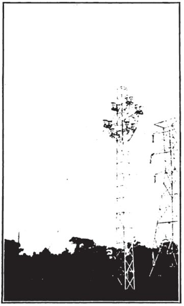
The illustrations printed with this article relate to a double-circuit 110-kv. line recently built from Kanai to a point near Tokyo, a distance of 83 miles. The average standard span is 600 ft., with a river crossing of 1,300 ft. Six conductors and two ground wires are installed, with a 10-ft. vertical spacing. Five different types of tower are employed for horizontal angles of 6 deg., 15 deg., 30 deg., angle suspension and tangent and angle anchor towers. The weight of the towers varies from 5,700 lb. to 13,000 lb. Most of the footings are concrete.
