[Trade Journal]
Publication: Electrical World
New York, NY, United States
p. 1439-1444, col. 1-2
Pin Insulators on 90,000-Volt Line
Changed from 60,000 Volts Delta to 90,000 Volts Y With Effective Relay Protection and Heavy Duty Oil Switches Found as Reliable as Former Voltage
By PAUL ACKERMAN
Shawinigan Water & Power Company, Montreal
ALTHOUGH it has been the customary practice to consider 60,000 volts to 70,000 volts as the limiting operating pressure for lines supported on pin-type insulators, the tests and experience of the Toronto Power Company, extending over a period of several years, have proved the feasibility of- using insulators of this type having only 150,000 volts wet flashover for 90,000-volt Y-connected lines, provided certain conditions are met. In general, these conditions are that effective relay protection and amply large circuit breakers are - provided. In addition, the insulators have to fulfill certain requirements, chiefly that they resist puncture and power arcs and that they be built to avoid internal stresses.
Under such conditions 90,000-volt (Y) transmission lines supported on pin-type insulators have proved virtually as effective and reliable as 60,000-volt (Y) transmission. Furthermore, lightning interference on the 90,000-volt lines has hardly increased compared with that on 60,000-volt lines. Although there are indications which tend to show that the insulation safety factor used on 90,000-volt operation represents about the lowest safe value, there are other indications which show that there still exists ample margin for average conditions. Analysis of the operating results on the Toronto system indicate that more reliable service, even at 100,000 volts, could be obtained, provided the transmission system could consist of three or more parallel lines separated from each other rather than in close proximity.
| |||
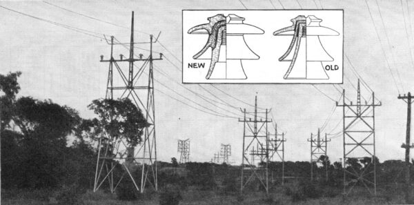
| Figs. 1 and 2New Pin-Type Insulators Used for 90,000-Volt Operation, and Old Type |
The significance of this experience is that it shows the feasibility of raising the line voltage of existing systems without expensive structural changes, except possibly improving the quality of the insulation and installing an effective relay system. This possibility may prove of great economic consequence to many companies since it will permit a large increase in their transmission line capacity without great expense. However, each case must be carefully considered on its own merits, since general operating conditions, the layout of the system, the importance of the service, the reliability of the insulators selected, the possibility of effective protection, etc., are all factors which influence the decision on such a change. Voltages of 60,000 to 70,000 are considered the practical operating limit for transmission lines using pin-type insulators, because it has always been assumed that safe operation necessitates a minimum of wet flashover of at least two to two and a half times the maximum line voltage, and because 150,000 volts to 160,000 volts wet flashover is the practical limit which can be obtained with pin-type insulators of the customary shape. If an attempt be made to build a pin-type insulator of higher wet flashover, it will become unduly large and heavy, or if built in detachable parts it will become mechanically weak by reason of the excessive height. The adoption of such a high safety factor as mentioned has been chiefly influenced by the enormous number of insulator failures experienced in the past and now fortunately being reduced.
CONDITIONS LEADING UP TO THE STUDY
The lines on which the observations resulting in the foregoing conclusions were made are trunk lines transmitting power from the Niagara Falls power plant to Toronto, a distance of 80 miles. The original installation consisted of one double-circuit steel-tower line with spans of approximately 400 ft. The conductors were arranged in triangular formation 6 ft. apart and consisted of 190,000-circ.mil copper cables. This line was put in operation in the latter part of 1906 at 60,000 volts, it being among the first lines to operate at this voltage.
In 1912 a second double-circuit steel-tower line was erected with 650-ft. spans and 8-ft. conductor spacings, using the same size conductor. At the same time step-up and step-down stations were re-equipped with modern 90,000-volt switching equipment of high short-circuit rupturing capacity, to meet the requirements of the increased generator capacity. The lines were to be reinsulated for 86,000-volt operation. At that time the insulator problem proved to be a rather difficult one, and it was finally decided to retain the voltage of 60,000, especially since prospective load conditions did not necessitate the immediate increase of operating voltagethe doubling of lines offering sufficient capacity.
 |
During the war years new conditions arose. One of the four lines was dismantled, the copper being used for other lines. Thus only three lines were left available for the Toronto load. At that time the idea of raising the line voltage was reconsidered, and it was decided that two lines at 85,000 volts would take care of the Toronto load just as well as three lines at 60,000 volts. Thus an increase in line voltage left the prospect of another line becoming available for other use. All lines also badly needed reinsulation. A change to two-line operation on higher voltage saved the expense of reinsulating the third line.
The possibilities of such a change were carefully studied and the observations led to the following conclusions:
(1) Economically, 90,000-volt operation could only be considered feasible if it were possible to retain the pin-type construction, since any change to suspension insulators would involve too great an expenditure.
(2) The largest economical size of a pin-type insulator having satisfactory mechanical strength and reasonable weight had a wet flashover of 150,000 volts. The ultimate permissible operating voltage on this type of insulator depended entirely on the wet flashover safety factor, which was considered necessary to assure safe operation. Observations on 60,000-volt lines over a period of several years showed that a transmission line with partly damaged insulation operating under trying weather conditions had continued to give service for hours or days until the damaged insulators were found and replaced. An analysis of such cases indicated that for such conditions a wet flashover of about 1.6 to 1.7 times the normal line voltage was sufficient to withstand any line surges except lightning. This flashover safety factor corresponds to 2.8 to 3.0 times the normal voltage to ground so long as the voltage to ground is balanced.
From these observations it was concluded that a pin insulator of 150,000-volt flashover would safely permit 90,000-volt operation, provided flashovers from lightning were accepted.
(3) Lightning flashovers were considered acceptable provided that the insulator was able to resist puncture and power arcs that would permanently disable the line and provided that the line circuit breakers were of sufficient rupturing capacity to clear the short circuits effectively.
From past operating records it could be hoped that about 75 per cent of the lightning short circuits would affect only one line at a time, despite the close proximity of the two circuits on one steel tower. With effective relay protection it could be hoped, furthermore, that all these short circuits would be cleared without interruption to service while operating on two lines in parallel. The remaining 25 per cent of lightning interferences had to be expected to involve both lines simultaneously, but this was not considered a serious matter, provided that the lines were not permanently damaged.
It was realized that 90,000-volt operation would possibly increase the total number of lightning shorts compared with 60,000-volt operation, but the increase was considered to be small.
Operation at 90,000 volts on one double-circuit steel-tower line and on pin insulators of 150,000 volts wet flashover was therefore considered quite safe and not more hazardous than the then existing 60,000-volt operation on three or four parallel lines, provided that (a) a puncture-proof and power-arc-proof reliable and permanent insulator was developed; (b) an effective relay protection for the double-line system was installed, and (c) flash-overs and occasional momentary interruptions from lightning were accepted.
(5) From investigations of experiences with insulators in preceding years it was concluded that the insulator must fulfill the following requirements to be safe on 90,000-volt operation: (a) its design and the quality of the porcelain must be such as to resist puncture when subject to flashover; (b) it must be glazed all over to eliminate deterioration due to porosity; (c) it must be made of heavy shells and of such shape as to avoid internal stresses so as to eliminate cracking due to sudden temperature changes and so as to offer reasonable assurance of resisting power arcs; (d) severe routine test and most careful inspection must be conducted at the factory.
(6) The relay protection had to be absolutely dependable and equally effective for short circuits from one end to the other extreme end of the line.
Furthermore, it was essential that the protection be instantaneous at either end so as to prevent the serious secondary disturbances on the synchronous load. From past experiences it was evident that the standard principle of protection with time-limit overload relays at the power-house end reverse energy relays at the terminal end of the line was not dependable enough and that a more positive and reliable scheme must be developed.
From the foregoing considerations it was realized that the whole success of 90,000-volt operation on pin-type insulators depended on a satisfactory solution of the insulator and relay problem.
FEATURES OF INSULATOR ADOPTED
By working in close co-operation with the porcelain manufacturer an insulator was developed of the shape shown in Fig. 2. As may be observed, the insulator is a three-piece unit similar in general appearance to the standard pin-type insulator, but differing considerably in details from the older type.
The new insulator differs chiefly in having thicker shells and more rounded shapes intended to avoid internal stresses. Preference was given to the three-shell insulator, as compared with the four-shell insulator, to obtain heavier individual shells at a fixed permissible total weight. The shells were glazed all over and had smooth sand-glazed surfaces to eliminate surface cracks and moisture penetration. About a thousand insulators were installed on the 60,000-volt lines during the winter season of 1916 to 1917 in order to obtain operating experience.
The relay problem was solved by developing a double-line protection based on the fact that with synchronous load and occasional steam power at the Toronto terminal a short circuit in one of the lines would cause an excess current in the faulty line compared with the sound line. Fig. 3 shows schematically the protection. This protection was installed early in 1917 on the 60,000-volt lines. In case of a short circuit within one of the two lines there will always be sufficient current difference between the lines to actuate relay B and thus trip the faulty line by the joint action of relays A and B. A detailed description of the protection and four years' operating results were given in a paper published in the April, 1921, issue of the Journal of the Engineering Institute of Canada. Tests and operating results proved the system fully effective.
With the relay protection fully up to expectation and the insulators offering promise of success (they had then been in operation too short a time to allow definite judgment), the essential problems for successful 90,000-volt operation were considered solved. As a result the change was decided upon early in 1918. During the summer of that year the lines were reinsulated with the new pin-type insulator. The strain insulators were taken down, retested, and good ones used again in strings of five to seven disks. A limited number of strain insulators of the well-known heavy type were also installed. By October of that year the reinsulation was completed and the change-over to 90,000 volts was carried out. Successful operation has been maintained ever since, and the results are fully up to expectations.
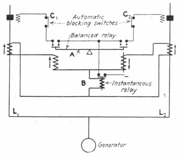 |
| Fig. 3Relay Protection Which Helped Make 90,000-Volt Operation With Pin-Type Insulators Possible. L1 and L2 Are the Two Parallel Lines. A Represents A Balanced Lever Which Moves to the Side of Heavier Current, Thereby Selecting the Faulty Line. B is An Instantaneous Relay Connected Differentially in the Current Circuit Between the Same Phase of the Two Lines, Thus Responding Only to A Difference in the Line Currents. the Purpose of This Relay is to Prevent the Balanced Lever From Tripping Any Line in Case of A Short Circuit Beyond the Line. the Lever Could Never Be So Perfectly Balanced That It Would Remain in the Horizontal Position With Equal Current in the Two Lines. the Lever Would Move to One or the Other Side and As A Result Would Trip A Line If the Relay B Would Not Keep the Trip Circuit Blocked Under Any Such Condition. Switches C1 and C2 Are Automatic Blocking Switches Controlled by the Oil Circuit Breakers in Order to Avoid Wrong Relay Action Under Certain Conditions. |
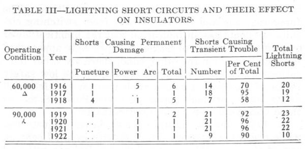
A summary of operating results compared with those obtained with 60,000-volt operation is given in Tables I to IV, and in the following paragraphs:
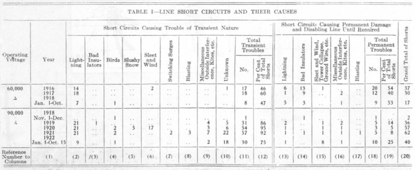
As may be observed in Table I, which shows the number of line short circuits and their causes for four years with 90,000-volt operation and for the three years preceding with 60,000-volt operation, the total number of short circuits (column 20) increased considerably on 90,000 volts. This would appear unfavorable, but upon closer investigation it will be observed that the low insulation safety factor is hardly to be blamed for this increase. Later it will be shown that the increased number of short circuits in no way influenced the service because of the effectiveness of the relay protection. In most of the short circuits troubles were of a transient nature (columns 11 and 12) and did not disable the line permanently. From columns 18 and 19 it can be observed that the troubles of a permanent nature have been reduced in number. Furthermore, the permanent troubles caused by damaged insulators have been reduced to a negligible quantity (columns 13 and 14), amounting to never more than two permanently disabled lines per year from this cause compared with as many as nineteen in 1916.
Improved insulation is entirely responsible for this marked change, showing that the quality of insulation is far more important than an excessive safety factor of flashover.
The causes of the large increases in troubles of transient nature can be seen from a study of columns 2 to 10. It will be noticed that the causes indicated in columns 6, 9 and 10 are the chief ones, none of them, however, being the result of low flashover safety-factor.
Sleet and wind (column 6) produce an entirely mechanical trouble due to wires whipping together. Miscellaneous outside interferences (column 9) were also due to mechanical causessomething coming in contact with the line. The increase in this kind of trouble compared with 60,000-volt operation is attributable chiefly 'to the grounded neutral, since most of these troubles were shorts of one wire to ground. On 60,000-volt delta operation these troubles would have caused a momentary ground without short-circuit disturbance.
Troubles of unknown origin (column 10) may be looked upon suspiciously as being caused possibly by the low flashover safety factor. It may be pointed out, however, that the majority of these troubles occurred during the summer time and during fair weather; that is, at a time when the flashover safety factor was high. Only three troubles occurred during rainy weather; that is, at a time of low flashover safety factor. Another significance of these troubles is the fact that most of them were single wire-to-ground flashovers. This was noticeable on one phase of the oil circuit breaker showing distress, the voltage and load disturbances being light. The foregoing indicates that these troubles were most likely due to birds or kites or outside interferences leaving no trace.
 |
The increased number of short circuits is attributable therefore to the grounded neutral and not to the low safety factor of flashover. The exceptionally large number of unknown troubles in 1921 is probably attributable in part to blasting operations on some large canal construction in the close vicinity of the lines.
The only troubles which could have been caused by the low flashover safety factor are those indicated in columns, 2, 3 and 5. Lightning (columns 2 and 13) would obviously have more tendency to cause flashover the lower the flashover safety factor is. However, operating results indicate that very little change can be observed from this cause. In fact, the lightning season of 1922 indicates a record in small number of lightning interferences compared with the best years of 60,000-volt operation.
The troubles due to slushy snow (column 5) may have been caused by the low safety factor of flashover leaving insufficient leakage path and thus causing a complete flashover. The troubles of this nature all occurred during the same storm under conditions of very heavy wet snow and a very strong wind which packed the wet snow underneath the insulator skirts. It is not impossible that this might have caused these troubles, but this condition seems to occur very rarely. Similar conditions had occasionally arisen previously, when operating on 60,000 volts. In this respect, therefore, 90,000-volt operation may in no way be considered worse than operation at 60,000 volts. There is also serious doubt whether the flashovers occurred on the pin-type insulators or on the strain insulators.
Megger tests on the strain insulators carried out about three months following the foregoing trouble dis closed the fact that there were several strings with only one or two good units, thus presenting a wet flashover of only 50,000 volts to 90,000 volts against the 150,000 volts for the pin insulator. Therefore it would seem more logical to assume that some of the strain insulators may have caused the flashover. Since 1920 the number of disks on strain insulators has been increased and a close inspection is made every year. No similar trouble has been experienced since. Snowstorms of the kind described have been reported since this change without apparent ill effect, but since it is rather difficult to compare the severity of storms of this kind, it is not possible to state definitely the actual cause of the former troubles.
Troubles from switching surges (column 7) have been almost completely absent. The two cases reported in 1921 occurred the same day, when a line was taken out of service, and during fair weather. Nothing was found on the lines to which this trouble could be attributed. Still, in view of the fact that no such troubles were experienced at other times, it is well to assume that at that time some transient trouble existed reducing the flashover value. No direct harm was caused by the switching surges so that their occurrence is not important. With modern sensitive settings on arresters it should be possible to eliminate such troubles entirely.
Operation during lightning storms has suffered in no way due to the low flashover safety factor, as may be observed from Table III. The total number of line short circuits from lightning is approximately the same with 60,000 volts and with 90,000 volts. On the other hand, there was a marked decline in the permanently disabled lines due to the superiority of the new insulator with respect to puncture and power-arc strength.
From an analysis of Tables I and III it can be clearly observed that the low safety factor of 'flashover is in no way responsible for the large increase in the total number of line shorts since operating on 90,000 volts. The increase is caused chiefly by the grounded neutral. On the other hand, the tables show that the improved quality of insulation has reduced the permanent insulator troubles to a negligible quantity despite the low safety factor of flashover.
EFFECT OF LINE TROUBLES ON SERVICE RECORD
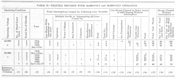
As shown by Table II, which indicates the service records obtained with 60,000-volt and 90,000-volt operation, the service has not been seriously affected by line troubles, despite the large increase in the number of short circuits, due principally to an effective relay protection and the fact that most of the troubles were of a transient nature. The total number of service interruptions (column 11) was slightly larger than with 60,000-volt operation, but in no way increased in proportion to the number of line shorts (column 17). This increase in the total number of service interruptions, however, is not attributable entirely to the low safety factor of flashover, as will be shown hereafter.
While operating on one single line, line shorts (column 4) are particularly responsible for the large number of total interruptions in 1920. This was attributable to the fact that the 90,000-volt system was only a double-circuit system, so that during a comparatively large part of the time operation had to be maintained over one line, while the other line was out of service for repair, inspection or other purposes. It is rather surprising, therefore, that this cause (column 4) does not have more effect with 90,000-volt operation than with 60,000-volt operation, where four parallel circuits were available.
The total number of interruptions while operating lines in multiple increased in general, as shown in column 10. The causes of such interruptions are tabulated in columns 5 to 9.
Lightning (column 5) seems to have a greater tendency to strike both lines simultaneously. This may be attributed to the reduced safety factor of flashover. In the writer's opinion, however, such increase is inci-dental, since the induced lightning voltage is of such great magnitude that the small change in safety factor of flashover could hardly have any significance. In any event the simultaneous interference with both lines was primarily caused by the close proximity of the two lines carried on the same steel tower and could be entirely eliminated if the two lines were separated sufficiently to avoid simultaneous interference.
All other interruptions (columns 7 .to 9) were caused by interferences where low safety factor of flashover is in no way responsible.
Total interruptions by tower collapse (column 6) due to extremely severe cyclonic windstorms were unavoidable in view of the fact that both lines were carried on the same steel-tower line.
The cause of unknown interference (column 8) was apparently a flashover blowing into the opposite line, thus causing a double-line short circuit, or else was the result of improper relay action due to rather limited generator capacity at that time.
Total interruptions due to miscellaneous outside interferences (column 9) while operating lines in multiple were all caused by a trouble starting on one line and spreading into the adjacent line because of its close proximity.
Line shorts cleared by relay action (columns 13 to 16) indicate how, with effective protection, line short cir-cuits do not have to be dreaded as much as- in former days.
As a whole, Tables I to III show why 90,000-volt operation can be considered as satisfactory as, or in fact better than, the previous 60,000-volt operation so far as line insulation is concerned, despite the low safety factor of flashover. All interruptions could have been saved by a trunk-line system consisting of three or more independent single-circuit tower or pole lines sufficiently separated to avoid spreading of trouble from one line to the adjacent one, provided that such a system was equipped with an effective relay protection. It is true that several serious shutdowns have occurred since operating on 90,000 volts, but the cause of these has been mechanical troubles, tower collapse and cable breakages due to exceptionally severe weather conditions. There is only one case that resulted in serious interruption (about one hour) which may be attributable to low safety factor of flashover. This occurred during the snowstorm of 1920, at which time for about an hour no voltage could be maintained on the lines. However, as previously mentioned, there is some reason for doubting whether the pin-type insulators or strain insulators were responsible for this condition. The foregoing case and the few shorts from switching circuits are doubtless an indication that the practical lower limit of safety factor of flashover is probably approached in these. lines. On the other hand, there are other indications which show plainly that, despite the low safety factor of flashover, a considerable margin of safety still exists under normal operating conditions. Some of these observations may be cited hereafter.
 |
In 1919, during lightning and heavy rainstorms, while operating only one line, and with isolated neutral, one of the line cables swung into a telephone pole and burned off. The cable fell to ground and produced a solid ground, thus raising the voltage to grbund on the two sound phases to 90,000 volts. Despite the low flashover safety margin on these two sound phases, no flashover occurred. The line operated thus for about ten seconds until the operator cleared the line.
When reinsulating the 'lines in 1918 the old strain insulators were retested and used again. By some over-sight one of the five disk strings was put up with four punctured disks and only one good disk, thus presenting a flashover of approximately only 85,000 volts dry and 50,000 volts wet. Still, the line operated successfully for two weeks on 90,000 volts in dry weather and failed only during the first rainy day, under which condition of course the flashover value of the bad string dropped below the normal voltage to ground.
Lightning flashovers often leave pin insulators with one of the three skirts broken. Yet yearly inspection always discloses a limited number of insulators with cracked skirts which are not causing any trouble despite the reduced flashover value. The inspection is carried out every spring, so that it can be reasonably assumed that some of these cracked insulators existed during the most trying time of wet snowstorms or other bad weather conditions.
FUTURE OF THE PIN INSULATOR
Insulator failures have been so numerous in the past decade that the advocacy of a low safety factor of flashover could only be justified if proof were given of a remarkable change in the quality of the line insulator. Based on a few years' experience only, it is rather difficult to make a definite statement on this point. Still, tendencies of insulator troubles show up usually within the first few years, so that the records of Table IV should offer a fair basis for judgment as to the future of the pin-type insulator used on these lines. According to columns 2 to 4, it will be observed that during the five years' service with this type of insulator only a very few cases occurred in which insulators caused permanent disabling of a line. Only one bad insulator was responsible for the disabling of a line (column 4).
In a few instances lightning caused some power-arc damage, but in only one case did it puncture the insu-lator, and then only the lower skirt. During two years' service there were only two punctures. In both cases the lower skirt was punctured and the upper shells broken off from the heat effect. It is easily possible that these two insulators may have been overlooked in the factory inspection. Therefore, it can be well hoped that the dreaded trouble of complete puncture as experienced on old insulators is virtually eliminated in this new-type insulator.
Power-arc damage (columns 3 and 5) cannot be avoided unless some arcing ring or horn protector is employed. The damaging effect from this cause, however, is so small, considering the large number of flash-overs, that no such complication was necessary.
Damage to insulators found on patrol and special inspection which had not caused line disturbances is enumerated in columns 5 to 7. An insulator was damaged by power arc during a lightning storm without, however, permanently disabling the line (column 5). The number of insulators damaged by malicious outside interference is shown in column 6. This is an unavoidable loss, but owing to the ruggedness of the new insulator this loss has also been reduced as compared with the old 60,000-volt insulator.
The only damage which raises some doubt as to the permanency of the new insulator is the one indicated in column 7. The old 60,000-volt insulator had developed temperature cracks in the head in an alarming way. Similar cracks showed up on the bottom disk of the new 90,000-volt insulator from the bottom rim upward. No sign could be detected of chipping, which would have indicated that the cracks were caused by stones or shots. Hence it was admitted that they might have been caused by excessive temperature changes. Upon close investigation it was found that 75 per cent of all the damaged insulators were in zones where injury to insulators from stone throwing had always been excessive. The remainder were all near country roads or other easily accessible places where outside interference would be quite possible. Not a single case was found at an isolated cross-country point. While, therefore, there is some doubt left as to the actual cause of these cracks, there is very strong reason to believe that the insulators were damaged by stones or shots.
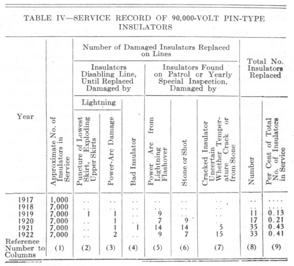 |
The records of Table IV are very encouraging and indicate plainly that the modern pin-type insulator is not afflicted with the serious ailments of the older type, but is becoming as reliable as any other part of the transmission line, provided that the proper type and quality of insulation is chosen. Operating experience on the 90,000-volt lines shows that it was perfectly justifiable to adopt a very low safety factor of flashover based on the assumption of being able to obtain a pin insulator of high quality and permanency.
Appreciation must be expressed to F. G. Clark, chief engineer of the Toronto Power Company, whose courageous and optimistic stand and confidence in the engineer's recommendation permitted the realization of this feat, which would have been considered reckless by the majority of engineers, but which has proved to be fully feasible and may have a considerable economic influence on future transmission engineering.
