[Trade Journal]
Publication: Transactions of the American Institute Of Electrical Engineers
New York, NY, United States
vol. 30, no. 128, p. 1536-1548, col. 1-2
A Study of Telephone Line Insulators
BY L. T. WILSON
Non-member
Synopsis.—This paper discusses the major factors contributing to the (total) leakage conductance of telephone line insulators, especially at carrier frequencies up to 50,000 cycles. The influence of both the design and material of the insulators and pins on each factor is discussed and illustrated by test data.
The electrical performance of three different designs is analyzed to illustrate, in a general way, the relative importance of the several factors.
INTRODUCTION
TO the layman, the long strings of large power insulators suspended from tall steel towers naturally present a more imposing picture than do the small telephone insulators mounted on the crossarms of relatively short wooden poles.
To the engineer, however, these little insulators present problems quite as stimulating and interesting in the telephone field as do the large insulators in the power field.
It is the purpose of this paper first to discuss briefly how some of these interesting problems arose and then to cover in more detail a study of the major phenomena involved in insulator leakage and finally to show how the knowledge gained from that study has helped bring about improved telephone insulators, some of which will be described.
ORIGIN OF PROBLEM
For many years the requirements of telephone insulators were relatively easy to meet because the frequency of the currents transmitted did not exceed about 3 kc. and because the leakage of insulators is generally low at such frequencies.
Therefore, the familiar glass insulators such as are shown in Figs. 1 and 2 sufficed, the former design (D. P. type) being employed on the longer circuits and the latter (toll type) or the shorter ones. Indeed they still suffice very generally, especially where only currents of voice frequencies or less are transmitted.
The advent of carrier systems employing higher frequencies ranging from about 3 to 30 kc. changed the insulator requirements substantially. At first these systems were few in number and relatively short in length and the insulator problem accordingly less important.
The rapid growth of carrier systems during the past decade,(1) the longer circuits to which they have been applied, and improved standards of long-distance transmission have all been factors in increasing the requirements imposed upon the insulator and in correspondingly augmenting the importance of the problem.
*Department of Development and Research, Am Tel. & Tel. Co., New York, N. Y.
1. See Carrier Systems on Long Distance Telephone Lines, H. A. Affel, C. S. Demarest, and C. W. Green, A. I. E. E. TRANS., Vol. 47, 1928, P. 1360-1386.
Presented at the Summer Convention of the A. I. E. E., Toronto, Ont., Canada, June 23-27, 1930.
It may now be remarked that the problem has been mainly one of securing economical insulators giving improved performance at these higher frequencies. In addition the low frequency performance of new designs had to be maintained substantially as good as that of the old designs.
LEAKAGE PHENOMENA
This study has been confined almost entirely to the pin type of insulator.
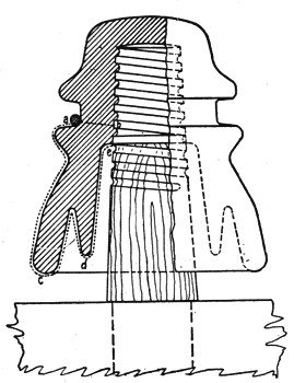 |
| Fig. 1—Standard D. P. Insulator and Standard Wood Pin |
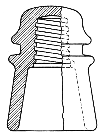 |
| Fig. 2—Standard Toll Insulator |
When an alternating potential exists between a pair of wires at the point where those wires are supported by insulators, a current flows from the one wire to the other. This current may be resolved into two components, one in phase with the potential and one in phase quadrature leading the potential.
This in-phase component which, of course, represents an energy loss is the one of chief interest here and in using the word leakage we refer to this component, or more accurately to its equivalent conductance.
Of course, both components in flowing through the resistance of the line conductors produce energy losses but these are so small as to be omitted here. Except these, all other energy losses which occur due to the presence of insulators whether they actually occur in the insulators proper or elsewhere will be charged to insulator leakage.
It is convenient to divide insulator leakage into several sources. This division is an arbitrary one, because some of the sources are not independent of each other and are, as will be seen later, difficult to separate experimentally.
The division follows:
A-c and d-c.
A. Leakage directly through insulator material to pin.
B. Leakage directly over insulator surfaces from line conductor to pin.
A-c. only.
C. Dielectric absorption in insulator material.
D. Dielectric absorption in pins.
E. Displacement current losses in crossarms and pins.
F. Losses due to unbalanced displacement currents in external resistances such as those of crossarms, poles, etc.
G. Displacement currents flowing over insulator surfaces through high resistance.
It should be noted that while all the items play a part in a-c. leakage only the first two enter in the d-c. case.
These items(2) will now be discussed individually and will be treated generally as they exist under wet rather than dry weather conditions. In this connection most of the experimental evidence that will appear was obtained from tests on insulator test lines located near Phoenixville, Pa. The measuring equipment employed there has already been described in another paper(3) and for lack of space will not be further discussed here although certain improvements have been made since that paper was prepared.
ITEM A—DIRECT LEAKAGE TO PIN
This item refers to that leakage through the insulator material which is directly due to the conductivity of the material, for example via path a b, Fig. 1. Item A has been listed chiefly for completeness because it is fairly well known that for most materials commonly employed, this source of leakage is very small. In the present study it has been found to be negligible in magnitude.
Item B, therefore, becomes the controlling source of leakage for direct current and accordingly deserves consideration. However, it will be given even more consideration because its magnitude, being so closely dependent on the shape, size, location, and condition of the insulator surfaces throws light on those factors which will later be shown to play a very large part in leakage for alternating currents.
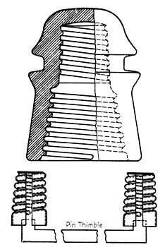 |
| Fig. 3—Standard C. W. Insulator and Pin Thimble |
ITEM B—DIRECT SURFACE LEAKAGE
1. General Characteristics. Item B refers to that leakage over the insulator surfaces which is directly due to the conductivity of those surfaces, for example, via path a c d e, Fig. 1.
The outstanding characteristic of this type of leakage is the enormous changes in magnitude it exhibits under changing weather conditions.
For example, Fig. 4 shows the results of measurements made on a telephone line in Texas equipped with insulators of the type shown in Fig. 3. This test, made in clear weather, shows the large change in leakage produced simply by the condensation of moisture on the insulator surfaces. The peak value may be seen to be about 2500 times the smallest value measured.(4) Had it rained along the entire length of line the peak might readily have been 10 times greater and the corresponding ratio would have been 25,000. These ratios are higher than would be commonly found because the line was quite new but they serve to indicate the wide range in the magnitude of this type of leakage.
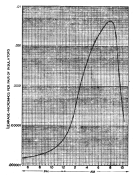 |
| Fig. 4—Illustrates Large Variation of D-C. Surface Leakage in Dry Weather |
2. The existence of several of these factors appears to have been well appreciated by Mr. R. D. Mershon as early as 1908, although Mr. Mershon's measurements were made at frequencies below 100 cycles where many of the items are extremely small in magnitude. See High Voltage Measurements at Niagara, by R. D. Mershon and Discussion, A. I. E. E. TRANS., Vol. 27, 1908, pp. 845-929.
3. See Methods of Measuring the Insulation of Telephone Lines at High Frequencies, E. I. Green, A. I. E. E. TRANS., VOL 46, 1927, p. 514-519.
4. Such tests indicate the negligible effect of Item A.
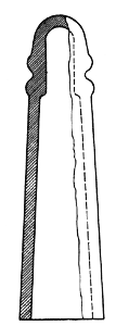 |
| Fig. 5 — Experimental Design With Long Skirt |
Fortunately, direct surface leakage even at its higher values in a sufficiently small part of the total leakage, especially at carrier frequencies, to make its wide variations substantially less serious than the foregoing ratios have indicated.
2. Influence of Insulator Design. To make this leakage conductance small it will be apparent from elementary considerations alone that the length of the path should be as great and its cross-section as small as possible. The latter depends on both the thickness and width of the moisture film, the width, in turn, depending upon the diameter of the surfaces.
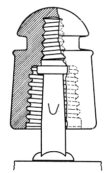 |
| Fig. 6 — Experimental Design With Short Corrugated Skirt (C. P.) Mounted on Standard Steel Pin |
The length of path may be increased by simply lengthening the insulator. The cross-section of the film may be made small by decreasing the diameter of the surfaces. Both methods are employed in the experimental design shown in Fig. 5 which will be recognized as extreme, at least with respect to mechanical strength. This design under test gives excellent performance for direct surface leakage, having under various weather conditions from one to 25 per cent as much leakage as the more reasonable design shown in Fig. 6.
Another, but somewhat less effective way of increasing the length of path is the use of one or more petticoats. This method has a mechanical advantage in keeping the over-all insulator length small but the effectiveness of the longer path is partly lost due to the necessary increase in diameter. An example of this method is the design shown in Fig. 1 which gives about half as much leakage as that of Fig. 2.
Still another way of increasing the length of path is the use of corrugations (Fig. 6, for example). The data at hand while not conclusive, indicate that corrugations are of questionable value.
The third dimension of the conducting path, namely its thickness, can be controlled to some extent by insulator design. The thickness of the water film is determined by the rate of rainfall and by a balance between the forces tending to make the film adhere to the surfaces and the force of gravity tending to pull the water away.
To reduce the amount of water intercepted by the insulator for a given rate of rainfall, it is again advantageous to make the insulator diameter as small as possible.
To facilitate the running off of the water intercepted, the surfaces in the conducting path should be nearly vertical and smooth. These remarks apply mainly to the outside surfaces.
As to the inside surfaces the situation is somewhat different. These are protected from direct rainfall and become wet by splashing, condensation, creepage, and by moisture carried by air currents.
To prevent splashing from the crossarm it might appear desirable to provide the insulator with a wide flaring kind of shed but experience has shown that such sheds may be quite ineffective or even detrimental. It will be convenient to discuss the action of one type of shed later.
It has been found preferable to employ an insulator of small diameter. The effects of the splashing can be reduced by placing the insulator higher from the cross-arm and by restricting the area of the opening between the pin and the insulator where the rising drops of water must enter.
These drops may readily rise a foot or more as casual observations show. To raise an insulator completely out of range obviously would lead to a cumbersome and mechanically unsatisfactory construction. However, some advantage may be had in elevating the insulator.
For example, consider Fig. 7 which shows the insulator of Fig. 6 mounted on a long pin. This pin, which was designed for another purpose, has an enlarged section which restricts the area between the pin and the insulator. The improved performance is, therefore, the result of two effects: one, that of elevating the insulator; the other, that of restricting the area between the pin and the insulator.
An attempt was made to separate these effects by providing a third set-up in which the insulator is mounted on the pin of Fig. 6, this short pin being supplied with a rubber washer of the proper size and location to simulate the enlarged section of the long pin.
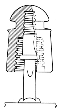 |
| Fig. 7—C. P. Design on Long Steel Pin With Baffle |
The relative performance of these three arrangements is given in Fig. 8 where S stands for short pin; S B, short pin with baffle; and L B long pin with baffle. These results were obtained during a hard shower within a month after the installation of the rubber washers and give some idea of the effectiveness of the two expedients.
In discussing the influence of insulator design on this type of leakage the question naturally arises as to the part played by the pin on which the insulator is mounted.
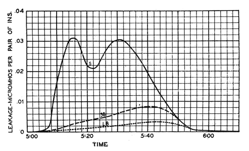 |
| Fig. 8—Illustrates Effect of Pin Length and Baffle on D-C. Surface Leakage |
Wood pins of the type commonly employed on telephone lines are found to contribute somewhat to the total insulation, depending on the dryness of the wood and on the efficiency of the insulator itself.
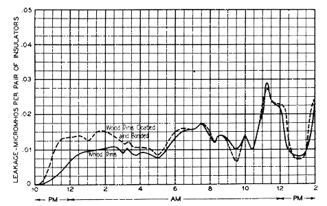
The effect of the pin may be measured by comparing insulators mounted on wood pins in the standard manner with similar ones mounted on wood pins which have been covered with a thin metal foil, the coatings of a pair of pins being electrically joined. Thus, both the pins and the crossarm between them are short circuited.
Fig. 9 shows the results of such a test on the type of insulator shown in Fig. 1. At the start of the rain and during the first few hours the wood appears to reduce the leakage considerably but as the rain continues and the pin takes up moisture its effect seems to decrease to nil.
 |
| Fig. 9—Illustrates Effect of Coating and Bonding of on D-C. Surface Leakage |
While similar tests on this and other types of insulators give corresponding results, still other tests indicate that at times, the wood continues to help out for many hours. One such test covering a period of about 23 hours showed, for this same type of insulator (Fig. 1), that the wood pin reduced the leakage by 30 per cent on the average.
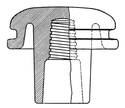
On the other hand, similar tests for the design of insulator shown in Fig. 10, very frequently show the pin to have negligible effect.
 |
| Fig. 10—Experimental Design (C. D.) |
While the foregoing tests have shown an advantage in favor of the wood pin, that conclusion holds only for the conditions of the test; namely, both wood and metal pins having the same diameter. When an insulator is specifically designed for a metal pin both the pin and insulator diameters can usually be made small because of the greater mechanical strength of the metal pin. The advantages of the design of small diameter, as previously discussed, may readily offset the slight disadvantage of the metal pin and the net result may be an actual gain.
3. Influence of Insulator Material. While the insulators are new, the molecular attraction between the insulator material and water plays a very important part; so important, in fact, that tests on such new insulators frequently give an unreliable basis on which to make decisions. On new glass insulators and particularly on those of borosilicate compositions, the rain water does not seem to wet the surfaces but rather stands in individual separate drops. The phenomenon is so marked that the surfaces have the appearance of having been oiled or waxed.
Under such conditions the conducting path is broken up and is discontinuous. Naturally its conductivity is very small. It would be fine if this property of the material could be preserved. Unfortunately along with exposure to weathering there comes an increasing tendency for the drops of water to spread out and unite to form a continuous path. Apparently, this action results from the collection of impurities on the surfaces, for such molecular phenomena are well known to be very sensitive to any contamination.
The direct surface leakage has been observed generally to increase 10 or more times after only a few weeks exposure. In one particular case where it rained the same day that the new insulators were installed, their surface leakage was observed to be less than one per cent of that measured on insulators of the same shape and material which had been aged for about two years.
This study of insulators has shown that while changes in design may affect changes in direct surface leakage by a factor of, say, 10, changes in kind of material affect this leakage by a factor of two or less after long exposure. In general, then, the material may be said to be less important than the design. Purely general considerations indicate this conclusion in view of the surface nature of the phenomenon. Consider an insulator of a given design exposed to the elements for several years. More and more foreign matter will collect on the surfaces as time goes on. It is obvious that as this process continues, the insulator material is becoming less and less important and it is conceivable, at least, that given time enough, this surface of foreign matter would determine the insulator performance irrespective of the material beneath this surface coating. At this point, design is paramount.
However, the material might be expected to influence the aging process in some way. From this viewpoint smoothness and hardness of surface, together with chemical stability, appear to be desirable qualities.
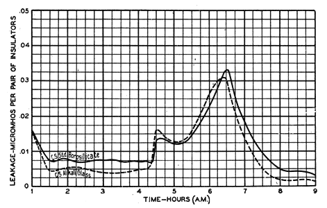
This study has been confined chiefly to various kinds of glass. In general, these have all had smooth surfaces, but they have varied in hardness and chemical stability. For example, borosilicate glasses are said to be generally harder and chemically more stable than the common alkali group.
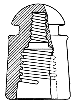
The relative performance of one sample from each of these respective groups is given in Fig. 11. Both were molded to the design of Fig. 12. This particular test which was made after more than a year of exposure shows only a small difference between the two glasses.
A previous test (exposure of nine months) showed quite the same results while still earlier tests had indicated the borosilicate as quite superior to the alkali glass.
While the foregoing tests illustrate the point made above as to the relative importance of design vs. material they cannot be considered as conclusive evidence on the relative merits of these two glasses for direct surface leakage.
 |
| Fig. 11 — Illustrates Effect of Insulator Material on D—C. Surface Leakage |
Probably more important than either hardness or chemical stability, which directly affect surface leakage, is the transparency of the material which affects leakage only indirectly, through the medium of insects apparently small spiders. These spiders build nests on the inner surfaces and seem to prefer dark or dimly lighted spaces for their homes. Therefore, the more transparent the insulator, the less attractive home it makes; and of opaque materials, probably white ones are accordingly less attractive than dark colored ones.
Other factors which enter into the spiders' choice appear to be those of space and of protection from the elements. These latter factors are functions of insulator design rather than material.
 |
| Fig. 12—Standard C. S. Design for Use With Standard Steel Pin |
There has been little opportunity to study these factors on the insulator test lines, due to the lack of spiders. Only one specific case has been found where their effect was marked. This was a case where small borosilicate insulators were given an opaque metal coating. After this coating had been on several months the direct surface leakage increased to several times the value for the similar uncoated ones. An investigation showed spider nests under many of the coated insulators.
On the other hand, several types of larger insulators have showed no such effect when coated, although some of these have been exposed for several years. These results are not conclusive. They merely indicate that design, as well as transparency of material, is a factor.
An experience of the telephone plant in the use of opaque insulator material (porcelain) showed a serious reduction of efficiency after a few years of exposure, apparently explained by the action of inserts.
4. Specific Conductivity of Film. The specific conductivity of the rain itself before it reaches the insulators is determined by the nature and amount of impurities collected in its fall. Both the kind and amount of impurities must vary greatly in different localities, for example, industrial centers as compared with open country. Then again, the amount in any given locality must vary throughout any storm on account of the cleansing action of the rain on the atmosphere.
On reaching the insulators the rain will suffer a further increase in conductivity depending on the impurities it finds there. Smooth vertical surfaces should be advantageous in reducing the collection of dust.
 |
| Fig. 13 - Illustrates Effect of Sheds on D-C. Surface Leakage. |
After a prolonged dry period in which the surfaces have become dust coated, the conductivity may be quite high at the start of rain. As the rain continues a certain amount of cleansing action occurs on the exposed surfaces and also to some extent on the unexposed surfaces, depending on the splashing. A decrease in leakage corresponding to this cleansing action has occasionally been observed.
Thus, in a locality where rain is infrequent but where dew, for example, might wet the insulators, the leakage might conceivably be quite high.
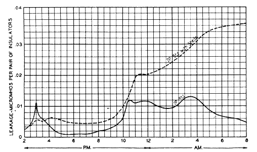
This phenomenon can be produced artificially and emphasized by placing roofs over the insulators, thus preventing any direct cleansing action of the rain.
Roofs of sheet metal six inches in height, five inches in width and twelve inches in length were placed over insulators of the design in Fig. 1. The ends were left open to permit passage of line wire.
While still new and clean these protected insulators showed less leakage than the unprotected ones of the same design. However, after a few months the protected insulators became covered with a thick layer of dust blown under the roofs by wind. Then when it rained, enough moisture reached the surfaces to wet the dust, but not enough to have much cleansing action. The surface leakage then becomes very high, as will be apparent from Fig. 13.
ITEM C — DIELECTRIC ABSORPTION IN INSULATOR MATERIAL
1. General Characteristics. When a dielectric is subjected to a varying potential field a certain amount of the electrical energy is dissipated in the material in the form of heat, depending on the nature of both the material and the field. This phenomenon is commonly called dielectric absorption.
Such a field exists between the line and tie wires on one side and the pin on the other. The insulator material lies more or less in this field and, therefore, dielectric absorption is naturally to be expected. While it is convenient to refer to a single insulator it should be remembered that two insulators are in series between wires at any one point.
The chief characteristic of the leakage resulting from this phenomenon is its variation with frequency. Approximately, it increases directly with the frequency. In the voice range its magnitude is generally negligible, but may become appreciable in the carrier range, particularly at the upper end.
Item C, like item B, increases in wet weather, but to a far less degree. This increase, which is brought about by the enlargement of the field caused by the wetting of the insulator surfaces, cannot be directly separated from the increases in the several other sources. Indirectly, however, a general idea of the magnitude of item C in wet weather can be obtained in the following two ways.
Both methods are based on the observation that the increase in capacitance between the wire and pin produced by metal-coating the outside of the insulator is invariably greater than the corresponding increase caused by wetting the uncoated insulator. For example, the increase due to coating the insulator of Fig. 3 exceeded the maximum increase observed for any rain by at least 40 per cent. More commonly this figure would be 100 per cent both for this and other shapes.
Therefore, if such metal-coated insulators (mounted on bonded metal pins for reasons appearing in the discussion of items D and E) be measured in dry weather the leakage conductance so found is likely to exceed by a substantial amount the wet-weather value of item C.
Another procedure consists in calculating the leakage of the metal-coated insulator. This method requires a knowledge of the wire-to-pin capacitance and the phase angle of the insulator material.
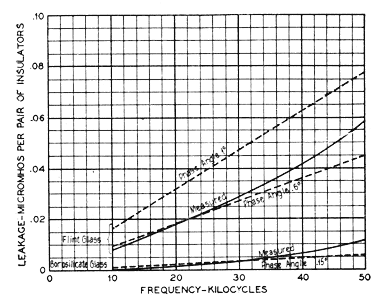
Fig. 14 shows the measured value for the insulator of Fig. 1 when molded from a clear flint glass. The phase angle of this particular glass is not known. However, the wire-to-pin capacitance is known. Using this known value, the leakage has been calculated for two measured values of phase angle for flint glasses, between which the value of this particular glass probably lies.
 |
| Fig. 14 - Variation of (C) With Frequency for Standard D. P. Design |
Similarly, the measured and calculated leakage are shown for this same design of insulator when molded from a borosilicate glass of known phase angle.
Neither method is capable of high accuracy, but they need not be for our present purpose of determining the order of magnitude of item C.
Consider item C at 50 kc. where its relative importance is greatest. At this frequency the metal-coated flint-glass insulator gave a measured leakage which is only about 10 per cent of the total wet-weather leakage of such an insulator as commonly used uncoated. So it appears that even at this high frequency, item C is less than 10 per cent of the total leakage of this particular design and material. This particular sample of flint-glass is not the best of the common alkali glasses nor is it the worst; so this round number of 10 per cent is a fair average value to use for alkali glasses.
The corresponding value for the borosilicate glass of which the sample was representative is about 4 per cent.
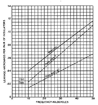
2. Influence of Design. The absolute magnitude of item C is influenced somewhat by design because of the effect of shape on capacitance. An idea of the magnitude of this effect can be obtained by comparing Fig. 14 with Fig. 15. Both designs were cast from the same batch of glass so that material plays a small part in comparing the two designs.
In general, for a given size of pin, the capacitance is decreased by enlarging the insulator diameter, particularly at the wire groove. Similarly, for a given outside diameter, the capacitance is decreased by making the pin diameter less. In general, too, the shorter the insulator, the less the capacitance.
Through the ordinary range of shapes the absolute magnitude of item C will not vary more than about three to one, and expressed as a percentage of the total wet-weather leakage, it is doubtful if item C, in the worst combination of poor design and poor material studied, could reach as high as 20 per cent.
The foregoing remarks apply to insulators on metal pins. When wood pins are used, the capacitance is less and C is correspondingly less. If the pin is dry, C is extremely small, if the pin is wet, C is still considerably less than it is for the same insulator on a metal pin.
3. Influence of Material. The range of the absolute value of C for various kinds of glass is much greater than it is for various designs. Phase angle of the material is frequently used as a criterion but Hoch(5) has shown that for insulator purposes, the product of phase angle and dielectric constant is a better criterion. Using the latter, a range of more than 20 to 1 is found for the glasses studied.
From the standpoint of item C alone, on account of its small relative magnitude there is little justification in going to high grade glasses, especially as these are more costly, unless other sources are first reduced sufficiently to make C really important.
ITEM D—DIELECTRIC ABSORPTION IN PINS
1. General Characteristics. Item D applies only to pins of dielectric material (usually wood) or to metal pins with cobs of dielectric material.
Like C, D is roughly proportional to the frequency and its importance is greatest at the upper end of the carrier range of frequencies.
 |
| Fig. 15 - Variation of (C) With Frequency for Standard Toll Design |
Again, like C, D increases in wet weather due to the accompanying increase in wire-to-pin capacitance. It also increases because of absorption of moisture by the pin.
5. See "Power Losses in Insulating Materials," E. T. Hoch, Bell System Technical Journal, Vol. 1, No. 2, November 1922, pp. 110-116.
Fortunately, due to the small value of C, particularly when dielectric pins are used, a rough measure of D can be obtained by again making use of metal-coated insulators.
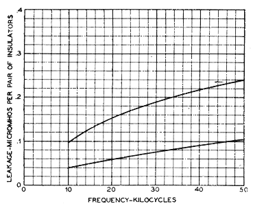
Fig. 16 shows two measurements of the leakage in dry weather of metal-coated insulators on wood pins. These insulators are similar in shape to that of Fig. 1, and were molded of a borosilicate glass.
Due to the low capacitance when wood pins are used and to the high quality of glass, item C can be neglected here.
 |
| Fig. 16 - Variation of (D) With Frequency for Standard D. P. Design |
Item E, which is to be discussed in the next section, enters here to some extent, but the cross-section of the crossarm is so much greater than that of the pins that this item, while it cannot be neglected, is probably small.
The measured leakage then closely represents that due to dielectric absorption in the pins under the conditions of the test, namely, metal-coated borosilicate insulators.
To the extent that metal coating gives greater capacitance than does wetting the insulator the value of D is magnified by these measurements. On the other hand, to the extent that the capacitance is reduced by the high quality of glass, the measurements give too low a value of D for alkali glasses.
As these effects approximately balance each other, the measured values are fairly representative of D for the alkali group.
The difference in the two values measured at different times is mainly due to the moisture content of the pins, the higher value corresponding to the higher moisture content.
Consider the insulator of Fig. 1 made of alkali glass and mounted on wood pins. Item C will be small, very small when the pin is dry; and while appreciably larger when the pin is wet, it is still considerably smaller than its value for a metal pin of the same dimensions. D, on the other hand, is large, even when the pin is dry; so in this example, D may be said to be considerably more important a factor than C.
In the case of this same design molded from a borosilicate glass, D becomes relatively even more important a factor.
2. Influence of Design. The general remarks which applied to C as to insulator diameter and length and as to pin diameter apply to D.
3. Influence of Insulator Material. For a given design, the lower the dielectric constant of the insulator material, the lower D will be.
4. Influence of Pin Material. Some study of this subject has been made, but the results are not sufficiently conclusive to report.
ITEM E—DISPLACEMENT CURRENT LOSSES IN CROSS-ARMS
1. General Characteristics. This item will first be considered as it applies to insulators on metal pins. The path of the displacement current is as follows: the current passes from one line wire through the capacitance of the one insulator to its pin, thence through the crossarm to the other pin and finally through the capacitance of the other insulator to the other wire. The capacitances of the two insulators are thus in series. The adjective "displacement" has been applied to the current because its magnitude is mainly determined by the insulator capacitance.
The losses produced in the crossarm by this current obviously depend on the electrical equivalent of the crossarm and on the insulator capacitance. If the former were a pure resistance with a magnitude small compared with the reactance of the series capacitances, then E would increase approximately as the square of the frequency. Experimentally, E is generally found to increase at a rate lying between the first and second power of the frequency over the range studied.
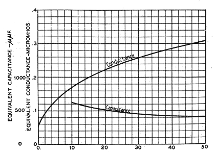 |
| Fig. 17 - Variation of Equivalent Parallel Capacitance and Conductance With Frequency for 25 Crossarms in Parallel Dry Weather Measurement |
A knowledge of the electrical equivalent of the cross-arm, together with the insulator capacitance, permits E to be calculated.
The constants of the crossarm between steel pins six inches apart, as measured on a dry day, are given in Fig. 17. From this measurement, the magnitude of E has been calculated for individual insulator capacitances of 4 and 20 m. m. f., and the results are shown in Fig. 18. The capacitances of most of the insulators studied lie within these two limits.
Fig. 18 also shows the value of E as measured for the insulators of Fig. 19. This measured value of E was obtained as follows: The leakage of the insulators was measured first with the crossarms short-circuited by tying a wire from each pin to the other. Then the wires were removed and the measurement repeated.
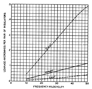 |
| Fig. 18 - Variation of (E) With Frequency in Dry Weather |
The difference between these measurements is E, if other sources are assumed to have remained unchanged. This assumption appears justified from the following test of its validity. The measurement of E, together with the measured constants of the crossarm, enables the insulator capacitance to be calculated. Such a calculation has been carried out and the value of capacitance so obtained checks very closely the value obtained by direct measurement.
The curves of Fig. 18 show that E may be large in dry weather. In fact, it is generally several times the magnitude of item C in dry weather and at the upper frequency range. Therefore, E is the controlling factor in dry weather.
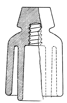 |
| Fig. 19 — British Post Office Design |
As to the effect of weather conditions on E, the increase in insulator capacitance brought by wet weather tends to greatly increase the losses. On the other hand, the large decrease in the crossarm impedance resulting from rain tends to decrease the losses. As a net result of these opposing effects, E is generally less in wet than in dry weather. In fact, after several hours of rain, E has been found to be almost negligible.
The upper curve in Fig. 20 shows E for the insulator of Fig. 1 foil-coated and mounted on steel pins with composition cobs. This curve was obtained in dry weather. The lower curve of Fig. 20 shows the magnitude of E for the same insulators after 1% hours of rain.
The equivalent conductance of the crossarms varies over a wide range depending on the weather. For instance, values of d-c. conductance 40 times as great as that recorded on Fig. 17 have been observed and the data indicated that still higher values are probable. The smallest observed value was one-tenth of that recorded in Fig. 17.
The experimental determination of the magnitude of E for insulators on wood pins is a difficult problem, because E cannot be readily separated from D.
The importance of insulator capacitance on E has already been established, so a knowledge of this factor for insulators on wood pins enables an estimate of E to be made.
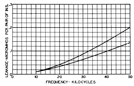 |
| Fig. 20 - Measured Leakage Due to (E) |
For example, the insulator of Fig. 1 on wood pins gives a measured capacitance in dry weather of about 4 m. m. f. E for this value is given by the bottom curve of Fig. 18. In this particular example, E is quite small in dry weather. The general decrease in E accompanying wet weather indicates that this item does not contribute much of the leakage of insulators on wood pins, at least after the crossarm is very wet.
2. Influence of Insulator Design. The wire-to-pin capacitance varies perhaps three to one for the designs covered in this study. The corresponding range in E is obviously great. Therefore, insulator design has an important influence on the magnitude of E.
3. Influence of Insulator Material. The materials studied have not shown a range in dielectric constant of more than about two to one. The corresponding range of wire-to-pin capacitance is even less; so insulator material may be said to have a relatively small influence on E.
4. Influence of Pin Spacing. Item E is naturally expected to be influenced by the pin spacing. However, the data bearing on this effect are too meager to report.
ITEM F—LOSSES DUE TO UNBALANCED DISPLACEMENT CURRENTS FLOWING IN EXTERNAL IMPEDANCES SUCH AS CROSSARMS, POLES, ETC.
1. General Characteristics. In general characteristics, F is very similar to E. As E is caused by a displacement current which flows directly from one line wire to the other via the crossarm in the manner already discussed, so F is similarly caused by unbalanced displacement currents flowing through cross-arms, poles, etc. There is not sufficient space in this paper either to present ,details of the theory of these losses or to describe the many interesting tests made to illustrate the effect.
In brief, F is due, first, to any difference that may exist between the capacitance of the insulator on one wire and that on the other wire, and second, to other unbalances in capacitance such, for example, as those caused by the presence of other wires.
The first of these causes will be recognized to be very similar in nature to a second order effect of E and is accordingly small in magnitude, at least if the same kind of insulator is employed on each wire; so F, due to this particular cause, is normally small.
The second source is the more important one. F, resulting from it, is greatest in dry weather, like . Here, F's importance is so great that transpositions in the insulator test line were found necessary, despite the line being only 200 ft. in length. The dry-weather leakage of many of the insulators under test is so small that, without transpositions, errors caused by the presence of other wires have amounted to several hundred per cent.
The variation of F with frequency is much the same as E.
Also, like E, F is less in wet than in dry weather.
The general remarks made in the discussion of Item E regarding the influence of insulator design and material apply also to F.
For the well transposed lines used for carrier circuits and for the reasonably well balanced insulator capacitances that the standard construction gives, F contributes little to the total wet-weather leakage.
ITEM G—DISPLACEMENT CURRENTS FLOWING OVER INSULATOR SURFACES THROUGH HIGH RESISTANCE
1. General Characteristics. Over the carrier range of frequencies this item is the most important source of leakage in wet weather. It probably contributes more than all other sources combined. On this account, it may not be amiss to repeat here an already known theory which fits the results of the present study fairly well.
Consider an insulator, the outside of which is wet. Divide this surface into elements of area and take, for example, one of them near the bottom of the insulator. Assume a small displacement current to flow from the pin to this element through the small capacitance which exists between them. Now for this current to reach the wire, it must flow through the thin film of moisture lying between the element chosen and the wire. This film offers a high resistance to the current, not high enough, however, to seriously limit the current, but, nevertheless, sufficient to produce heat losses. These losses when integrated over the entire insulator surface become important and qualitatively, at least, account for the characteristics of item G.
 |
| Fig. 21—Electricals Equivalent of An Insulator for the Production of (G) |
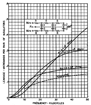
Fig. 21 shows in much simplified form an electrical equivalent of this action. An inspection of this figure will throw some light on the subject.
For one thing, it is clear that the apparent wire-to-pin capacitance will decrease with increasing frequency. Wet-weather tests invariably show this effect. (Incidentally, this effect tends to reduce the magnitude of C and D, at the higher frequencies.)
It is also apparent that the conductance of this simplified circuit is zero at zero frequency and a maximum at very high frequencies. In the intervening range the conductance at first rises nearly as the square of the frequency, then the relations becomes more nearly linear and finally tapers off to a final constant maximum value.
 |
| Fig. 22—Calculated and Measured Value of (G) for C. P. Insulator |
If the distributed capacitance of an insulator were accurately known, as well as the resistivity of the surface film, the magnitude of G could be calculated. Unfortunately, both factors are difficult to determine with precision.
However, it is useful to carry out such a calculation, even though the factors be not accurately known.
Fig. 22 shows the variation of G with frequency, as calculated for the assumptions indicated on the drawing. The assumed distributed capacitance and surface resistivity are intended to represent those of the insulator of Fig. 6. A measured value of G for this insulator is shown by the dotted curve. The agreement is not very good, being no more than qualitative. However, the accuracy of the assumptions is not sufficiently high to expect a much better agreement.
In accordance with this theory, it is evident that G could be produced on a dry insulator by coating the surface with a thin metallic film of high resistance. This has been checked experimentally. The dry-weather conductance of an insulator of given shape and material can readily be increased ten or more times by such a coating. In its general magnitude this increase corresponds to that of the uncoated insulator between dry and wet weather.
Referring again to Fig. 21, G will be seen to be zero when the resistivity of the circuit is zero. Thus, if a metal coating of low resistance be placed on the outside surface, the value of G would be made negligible for that surface. However, such a coating causes the losses on the inner surfaces to increase. The net result is usually a substantial reduction in leakage, as shown by many tests comparing coated with uncoated insulators.
2. Influence of Insulator Design. From the foregoing discussion, the importance of insulator capacitance is quite apparent. For G to be small, it is not only desirable that the total capacitance shall be small, but particularly that any capacitance remote from the wire groove be small, unless the resistance of the path from wire to that capacitance can be maintained at a very high value.
Insulator design is important from this standpoint. It is also important because of its relation to the resistivity of the surface film, as was discussed in some detail under B.
3. Influence of Insulator Material. In general, the influence of insulator material has been less than that of design, especially after the insulator has aged for a couple of years. The influence of material on G is determined both by the dielectric constant of the material and its surface resistivity.
While the dielectric constant of the materials tested varies about two to one, the corresponding range of G is very much less, on account of the low dielectric constant of the air which occupies a part of the dielectric path.
The factor of surface resistivity is probably the more important one. For example, its effect on G probably accounts for most of the increase in leakage at high frequencies that accompanies aging, which is a very substantial one.
As to the relative importance of these two factors, tests have been made on only one design. At this writing the tests register a slight balance in the favor of a good surface over a good (low) dielectric constant.
The influence of material on G, while not great, gives the chief justification from the electrical standpoint for employing the better but more costly glasses.
CONCLUSION
Description of New Insulators. Two new insulators are available for use on carrier circuits of the Bell System. These replace the standard D. P. insulator of Fig. 1 in those cases where the additional expense of the new insulators is justified.
One of the new types is designed for use on the wood pins of existing lines. It is known as the C. W. insulator and its design is shown in Fig. 3. The pair of pin thimbles illustrated at the bottom of that figure is first placed over the two wood pins, then the insulators are screwed into place over the thimbles, forcing the latter well into the threads of the wood. The thimbles are constructed of thin copper and are bonded together by a tinned copper strip.
The other new type is designed to screw directly over a steel pin. This is known as the C. S. insulator and its design is shown in Fig. 12. At each crossarm the two steel pins are bonded by means of a wire underneath the arm.
 |
| Fig. 23 — Relative Leakage of D. P., C. W. and C. S. Insulators As Measured at Phoenixville, Pa.. in Moderate Rain |
Both new designs are molded from borosilicate glass. This glass is more expensive than the alkali glass used in the old D. P. design. On this account, and on account of the pin thimbles in one case and the steel pins in the other, the new insulators cost more to install than did the old ones.
Both of the new designs were brought out several years ago before this study had conclusively demonstrated the importance of surface losses (item G). It will, therefore, be of some interest to discuss their performance in the light of the more complete knowledge.
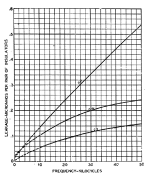
Performance of D. P., C. W., and C. S. Insulators. The leakage of these three types, as measured on the insulator test line at Phoenixville, Pa., in a moderate rain, is given in Fig. 23. This measurement does not give a true picture of the relative efficiency of the three types because no two of them are aged alike. Besides, the relative efficiency varies considerably with different weather conditions. However, the measurement will serve our present purpose, which is to analyze the total leakage of each design and thus give a perspective which could not well be brought out in the detailed discussion of the several sources of leakage. It should be pointed out and emphasized that the allocation of the total leakage to its component parts can be only very approximate.
 |
| Fig. 24 — Estimated Allocation of Leakage for D. P. Insulator |
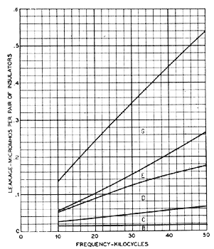
Fig. 24 shows an estimate of the leakage contributed by the several sources for the D. P. design. The leakage directly through the insulator material is negligible and item A, therefore, does not appear. Similarly, the leakage due to unbalanced displacement currents flowing in crossarms, poles, etc., is considered negligible and, therefore, item F does not appear.
At a frequency of 30 kc., for example, B, the direct surface leakage or d-c. leakage, is about 5 per cent of the total. The dielectric absorption in the glass C is about 10 per cent. The dielectric absorption in the wood pins D is about 20 per cent. The crossarm losses E contribute about 10 per cent and, finally, the losses on the insulator surfaces G contribute about 55 per cent.
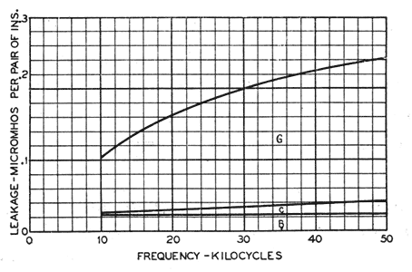
Fig. 25 shows a similar estimate for the C. W. design. Here the bonded pin thimbles shield the wood pins from any electric field and thus eliminate dielectric absorption D from the pins. Similarly, by short-circuiting the crossarms, the losses occurring there are eliminated. Accordingly, both items D and E are made negligible and do not appear.
Of the remaining factors, the direct surface leakage B contributes about 12 per cent of the total (at 30 kc., for example). The losses in the glass C are liberally estimated at about 5 per cent. Finally, the surface losses G contribute over 80 per cent of the total.
Comparing the C. W. performance in this test with that of the D. P. we find that most of the improvement shown by the C. W. has resulted from the elimination of items D and E. Due to the single skirt design of the C. W. and the pin thimbles, item B has been increased in magnitude. The loss in the glass C has been decreased by the use of borosilicate glass. However, the most important item G has been only slightly reduced, and if C. W. insulators in this test were aged as far as the D. P., the C. W. might show no improvement with respect to G. The pin thimble construction tends to increase the insulator capacitance and thus tends to make G larger for the C. W. than for the D. P. design. The use of a borosilicate glass with its lower dielectric constant counteracts this action somewhat.
 |
| Fig. 25—Estimated Allocation of Leakage for C. W. Insulator |
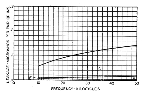
The estimated division of losses for the C. S. design is given in Fig. 26. The use of metal has eliminated any dielectric absorption D from occurring in the pins. The bonding of the pins by wire has eliminated crossarm losses E.
Of the remaining factors, the direct surface leakage B contributes about 4 per cent or less of the total at 30 kc. The losses in the glass C are liberally estimated at 10 per cent or less, while the surface losses G contribute about 85 per cent or more.
 |
| Fig. 26—Estimated Allocation of Leakage for C. S. Insulator |
In this design the absolute magnitude of B has been decreased somewhat, chiefly because the small diameter of the steel pin permits a small diameter of insulator, the advantages of which were pointed out in the detailed discussion of this item.
The low capacitance made possible by the small steel pin has helped to make both C and G relatively small, although most of the improvement in C is due to the borosilicate glass.
The improvement in the surface losses G over the D. P. design is quite marked.
For the new designs the two factors B and G are the controlling ones. In this particular test B happens to be quite small in magnitude, and would naturally lead one to conclude that B had been made unnecessarily small at the expense of G, especially since these two items in many respects place conflicting requirements on insulator design. However, B has been observed at times to reach a value as high as one-third of the total leakage at 50 kc. The necessity of engineering for such cases makes the design more reasonable, especially when it is recalled that the insulators must serve for direct current and low frequencies, as well as for the carrier range.
Of the new designs, the electrical superiority of the C. S. over the C. W. design is apparent. This fact, together with economic considerations, has led to the almost universal choice of the C. S. rather than the C. W. type for the field of application of the new insulators in the telephone plant.
The utility of the C. S. insulators in the telephone plant will be more clearly apparent from a consideration of the reduction in attenuation which their use brings about.
The losses in transmission over a pair of wires at carrier frequencies come chiefly from two sources: one, substantially fixed in magnitude, depending mainly on the resistance of the wires; the other, quite variable in magnitude, depending on the leakage conductance between the wires and, therefore, on the weather.(6)
In the case of 165-mil copper wires on 12-in. spacing these two components of loss are approximately equal in wet weather when the older type of insulators are used. The C. S. type cuts this variable component about in half at 30 kilocycles thus reducing the total wet-weather attenuation of these wires to about 75 per cent of its former value. For smaller sizes of wires the percentage reduction is correspondingly less.
The benefits of the lesser attenuation can be utilized in the plant in various ways, depending on local conditions; for example, in increasing repeater spacing, in employing smaller gages of wires, or in increasing the number of insulators per mile to provide for better transposition designs.
In addition, the new insulators, in having reduced the variable component of loss, improve the stability of carrier circuits to a marked degree.
ACKNOWLEDGMENT
Only the electrical features of the new designs have been discussed. Closely related to these are the many mechanical problems which naturally arise in new construction. These latter problems, during the development of the new designs, came under the supervision of Mr. C. S. Gordon, assisted by Mr. J. T. Lowe.
The Corning Glass Works has cooperated in molding special experimental insulators of various compositions.
Data on the electrical properties of numerous glass compositions have been supplied by the Bell Telephone Laboratories.
The writer desires to express his thanks to Messrs. F. A. Leibe, L. R. Montfort and L. Staehler for assistance in the measurements and to Mr. H. R. Nein for assistance in the preparation of this paper.
6. For a more detailed discussion of attenuation see a parallel paper, The Transmission Characteristics of Open-Wire Telephone Lines, by E. I. Green.
