[Trade Journal]
Publication: Electrical World
New York, NY, United States
p. 1186-1187, col. 1-3
Insulators Resist Rifles
Bullet Breakage Reduced by "Glance" Design Which Makes Minor Sacrifices in Leakage Path
By G. M. WHISLER
Westinghouse Electric & Manufacturing Company, Emeryville, Calif.
Reducing insulator breakage by missiles and bullets is a desirable contribution, especially if it can be accomplished without compromising on electrical design and performance. It does not happen everywhere, but where it does there is need for something to combat it. These tests show why experience in the West has been bettered in this respect in the last two or three years.
FIELD reports have indicated that insulator breakage has been largely due to shooting with small caliber rifles. Preliminary work in developing a more rugged design was on available standard suspension insulators, using a Marlin model 38 repeating rifle with 22 long cartridges. We assumed that no one would be foolish enough to stand directly under the pole or tower and shoot up at the insulators, and therefore chose an angle of 30 deg. from the axis of the insulator and a distance of 60 ft. for the line of fire. For convenience in recording hits and the results, the insulator under test was balanced on the ground with the axis of the insulator horizontal and the cap at the back supported to maintain this position. Our data were recorded using hour hand positions for the radial location of the hit and a letter to indicate the exact point (Fig. 1). Thus, a hit at the very top edge would be A-12, at right edge A-3, etc. Preliminary tests indicated definitely:
1. That a standard shape and weight of suspension shell would not withstand such shooting (Fig. 2a).
2. That ruggedness could not be obtained merely by increasing the thickness and weight of the shell.
3. That the shape of the shell was a very important factor. It should be such that the bullet will be deflected and not exert its full force at the point of impact.
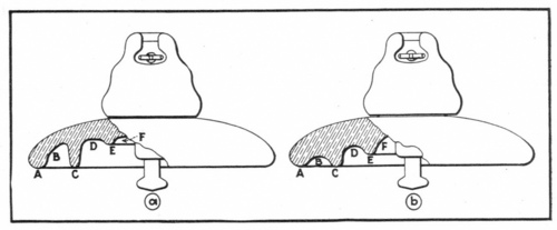 |
| Fig. 1Design B Resists Impacts Better Than A. Letters Indicate Points of Hit Cited in Table I. \"Hour Hand\" Time Used There to Indicate Angle of Incidence. |
| |||
| Fig. 2Glance Design (Fig. 1 B) Deflects Impact Without Breakage. After Twenty Shots There Was Only A Bit More Chipping of Glaze Than Shown Here for Ten Shots. |
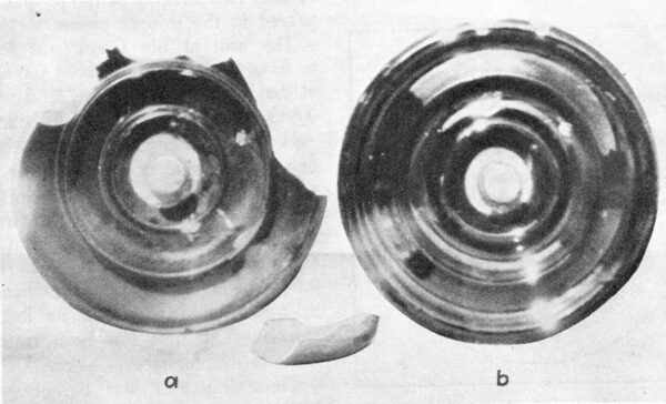
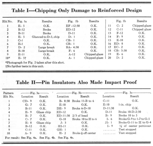
Shells were produced designed to incorporate the features found necessary in our preliminary tests and subjected to the shooting test with results as indicated by Fig. 2b. The data taken from shooting tests, results of which are shown in Fig. 2, are shown in Table I. In all of these tests no conductor or clamp was in position. This made the units more vulnerable than in service, since the clamp and conductor would protect about half of the shell.
 |
From the results of several tests on the type of units shown in Fig. 1b the following points were determined:
1. On random hits, as for example those listed in Table I for Figs. 1 and 2, units will successfully withstand more abuse than should be expected in service.
2. The bullets are definitely deflected and do not exert their full impact force at the point of first contact with the porcelain. Some of the lead paths indicated that the bullet was deflected over as much as 3 in. of surface and then left the porcelain. This action is best shown in Fig. 7.
3. Repeated direct hits at or near the same spot, particularly points A or C (Fig. 1) may result in relatively small breaks, which rarely extend in further than point C, retaining the bulk of the insulating value.
This development work on suspension insulators was completed about three years ago and met with favorable response almost immediately. To date Western utility companies have purchased several thousand units. The contractor who installed the bulk of these reported very favorably on this design. We have had no reports so far of breakage from shooting or stone throwing on the lines using this design (Fig. 1b).
Pin type also modified successfully
Following the work on the suspension type insulator consideration was given to the pin type. Fig. 4 shows three pin-type insulators on which shooting tests were run. Ten shots for each unit were made with hits as indicated in Table II.
| |||
| Fig. 4Shattering Overcome by Sturdier Pin Insulator |
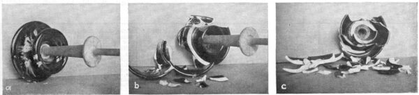
The illustration in Fig. 4 shows the condition of these insulators after the shooting test and correspond to design details shown in Fig. 3, units a, b and c, respectively. Units b and c of Fig. 3 were existing standard insulators. Unit a was produced to meet the requirements found necessary in the work on suspension insulators. This unit happens to be a one-piece design, but similar results could doubtless be obtained in standard multi-part designs.
The work done at present indicates that designs can be produced which will stand considerably more abuse from shooting, handling or stone throwing than previously existing designs. The features involved add to the weight and sacrifice some leakage distance for a given height and diameter of insulator. This is shown by the following table of data for both designs:
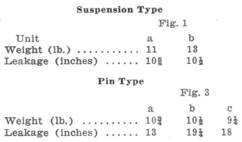 |
Because of this leakage distance loss the new units should only be used where breakage is a serious problem and the lost leakage distance can be sacrificed safely.
