[Trade Journal]
Publication: Electrical World
New York, NY, United States
p. 1894-1896, col. 1-3
Line-Post Insulators Prove Worth on 66-Kv. Line
New Design Helps Public Relations by Minimizing Radio Interference, Saves Money by Increasing Ground Clearance and Reduces Cleaning Costs
By FRED B. DOOLITTLE
Radio Engineer Southern California Edison Company, Ltd.
DISCOVERIES which lead to scientific advances are often made by accident or coincidence. Such was the case in the development of the "line-post insulator," the fundamental idea of which was conceived more than four years ago as a result of observations made in the testing laboratories of the Southern California Edison Company, Ltd. In the course of investigating various insulators and line materials to find those which could be used on high-voltage lines without causing radio interference, a large number of samples were tested in the presence of various manufacturers' representatives.
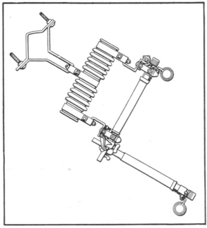 |
| Fig. 1Forerunner of the Line-Post InsulatorThe Conventional Fuse Holder. |
After testing many pin-type insulators of standard and "treated" designs with generally disappointing results, a fuse holder similar to Fig. 1 was tried. To every one's surprise, very high potential could be applied between the fuse clips and the mounting bracket without causing radio interference. The porcelain insulating medium in this fuse holder consisted of a hollow tube closed at the upper end and having "petticoats" on the outer surface very similar to those on some of the "fog-type" pin-type insulators which previously had been tested and found to cause radio interference at much lower voltages.
The similarity in appearance of the porcelain in the fuse holder and the pin-type insulator led to the thought that the difference in the voltage at which radio interference started must be due to the pin. This opinion was verified by filling the porcelain tube with a conductor and applying potential between the mounting bracket and the conductor, this combination showing results that are comparable to those obtained on the pin-type insulators.
Tests were made at night in order that corona might be observed in the dark and the conclusion, jestingly suggested, was that from the standpoint of radio interference fuse holders made the best line insulators.
Apparently taking the test results seriously, one manufacturer's representative early the next morning appeared before Edison company engineers with an idea for a new type of insulator. This manufacturer had been conducting similar tests at his plant during a period of a year or more previous and the results of this test confirmed his own findings. His idea was soon translated into working drawings of the first line-post insulator, at that time called the "pinless pin-type insulator."
Samples of the new insulators for service at a line voltage of 66 kv. were soon received and passed rigorous radio interference tests without difficulty. Minor changes were made in the original design to eliminate the possibility of interference originating at the line and tie wires. Inspection of the accompanying illustration will show that the 66-kv. insulator is a one-piece porcelain cylinder approximately 20 in. high with an outer surface having petticoats very similar to those of the fog-type suspension insulator. One end is grooved to receive the line conductor and tie wires. The other end is cemented into a base which, by means of a stud screwing into the base, permits the insulator to be mounted on top of the crossarm similar to the conventional pin-type design.
| |||
| Fig. 2Original Installation of Line-Post Insulators on the Southern California Edison System. at Left, Construction in the Business Section and, at Right, in the Residential Area. |
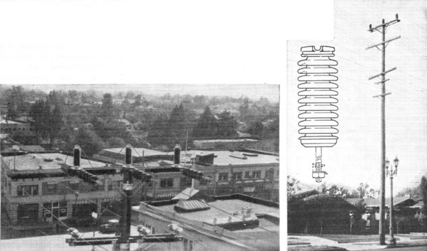
Assured by the results of radio interference, flashover and mechanical tests on the new insulator and anticipating protests from property owners in a certain locality should existing poles be replaced by larger poles, the Southern California Edison Company decided to use line-post insulators instead of taller poles on about 2 miles of this line. In so doing the company departed from its standard construction of suspension insulators for 66-kv. lines, a radical change in practice, as the use of pin-type insulators heretofore had been avoided on lines of this voltage because of the probability of creating radio interference.
No more radio interference
The reinsulated line extends through a residential section into a business district (see Fig. 2). In nearly three years of operation at 66 kv. there have been no radio interference complaints. Attempts have been made at various times to detect any radio interference that might be caused by this line by having the line energized and de-energized while listening under it with an automobile radio receiver. No difference in noise level was ever observed on these tests, there being some slight 'interference from other sources, which of course was not affected by switching the 66-kv. line.
Having found an insulator which gives satisfactory performance with pin-type construction on 66-kv. lines, it is of some interest to consider a theory which explains why line-post insulators are inherently less likely to cause radio interference than conventional pin-type insulators. With an insulator causing interference, tests show that the same intensity of interference is measured whether the instrument is connected directly in the ground lead to the insulator pin or with the instrument connected through a condenser of low radio frequency impedance to the energized side of the insulator. This demonstrated that the interference is due to a radio-frequency current flowing through the transmission conductor and insulator capacitance and is not due to shock excitation of some portion of the circuit.
Cleaning easy on line-post insulators
Since the capacitance of the line-post insulator is very small compared to that of a pin-type insulator, it offers a much higher radio frequency impedance to the flow of current in the line-to-ground path and therefore limits this current to a low value or prevents its flow entirely. This low capacitance also minimizes the charging current at power frequency and in so doing reduces the probability of interference being produced by excessive current density at the contact between the tie wire and porcelain if a metal cap is not used.
Laboratory tests on line-post insulators, in which attempts were made to simulate field conditions of extreme contamination and moisture, produced results which raised serious question as to the serviceability of the insulators on lines subject to severe exposure along the seacoast. Specifically, in the laboratory with the insulators subjected to salt water spray, very severe periodic arcs were observed which extended as much as two-thirds of the length of the insulators. There was enough current involved in these arcs momentarily to dip the voltage of the test transformer, and it was therefore not known whether or not complete flashover would have occurred had the voltage been maintained.
A field test then was made by installing a line-post insulator on an operating 66-kv. line in a location of severe exposure and allowing it to remain without cleaning until it flashed over. This occurred in almost exactly one year from the time the insulator was installed, which was considered satisfactory performance, because if this insulator had been cleaned according to the schedule applying to the suspension insulators on the same line the flashover would have been prevented.
After flashing over the insulator was cleaned and the line re-energized, the damage to the insulator being slight. Cleaning of line-post insulators is a very much easier operation than cleaning of conventional suspension strings.
Design withstands severe stresses
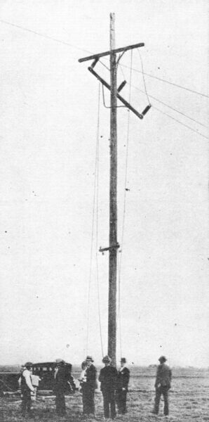
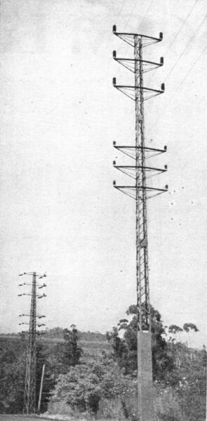
Although the mechanical strength of line-post insulators was known as a result of tests, some doubt existed as to the ability of these insulators to withstand such shock as might result from failure of a conductor in a span. Before going into the more extensive application of line-post insulators they were tested by replacing the suspension insulators on one pole of a transmission line with the new design of insulators. The conductor was No. 4/0 copper, the span length 165 ft. and the tension 1,485 lb. The center conductor was cut in the center of the span without any apparent effect on the insulators. Then one of the outside conductors was similarly cut, with the result shown in Fig. 3, the pole split and the arm pulled loose, but there was no damage to the insulators. This test convinced the most skeptical and it was decided to use line-post insulators on about 1 mile of new line extending from the end of a tower line in the mountains to the substation in the city of Santa Barbara. Fig. 4 shows this line insulated with line-post insulators for two circuits at 66 kv. and two circuits at 16 kv. There have been no radio interference complaints from residents in the vicinity of this line and consequently no radio interference tests have been made.
| |||
| Fig. 3Mechanical Test of Line-Post Insulators Made by Cutting Conductors. Damage to Pole and Crossarm is Apparent, But the Insulators Were Unharmed. |
| |||
| Fig. 4Line-Post Insulators on Steel Tower Line Carrying Two 66-Kv. Circuits (Above) and Two 16-Kv. (Below). |
To January, 1935, the Southern California Edison Company, Ltd., has 612 line-post insulators in service on 66-kv. lines. About 400 of these are on the two lines pictured in Figs. 2 and 4. The remaining units are scattered over the system, a considerable number having been used to replace suspension insulator strings where it was necessary to raise the conductors to clear trees.
The advantage of freedom from radio interference, the inconspicuous, neat appearance and the ease of cleaning of line-post insulators, together with the advantages common to them and conventional pin-type insulators, of less pole height for the same ground clearance and lower cost than suspension strings, all point to a bright future for this newcomer in the field of high-voltage line insulation.
