[Trade Journal]
Publication: Telephony
Chicago, IL, United States
vol. 152, no. 17, p. 17-20, 74-75, col. 1-3
The Topographical Plan of Rural Plant Design
By EARL SEEMAN and MILTON SEEMAN
ON FEB. 8 of this year we watched a new rural line we installed in 1956 go down under a loading of ice, but without the usual alarm or discouragement that we have experienced numerous times before because these new lines were built to comply and cooperate with such sleet storms.
Ours is a typical small one-exchange Independent company (800 stations), perhaps with one exception; that being our geographical location as we are located in southwestern Minnesota on the states highest elevation that constitutes a continental divide where the waters separate westward into the Missouri River and eastward into the Mississippi River. Sleet is a frequent visitor and high winds with variable velocity seem to be constant.
| |||
| Earl Seeman |
| |||
| Milton Seeman |
Consequently, our problem of maintaining dependable rural telephone service in our area against adverse climatic conditions have led us to pioneer a revolutionary and new concept in the design of rural open wire plant.
Our plan to go dial involved considerable replacement of rural plant that was beyond the point of rehabilitation due to age and repeated damages from ice loadings.
At the 1956 Minnesota telephone convention we viewed an exhibit of new materials to facilitate the topographical plan of rural plant design, a new theory that is designed to prevent the loss of aerial plant to the destructive forces of nature. This is revolutionary in the respect that the nature of the terrain establishes the general engineering procedures and allows aerial wire to yield to, and return to its original position from, ice loading by virtue of the wires ability to stretch. This permits aerial plant to yield without breakage to wire and supporting structures, rather than defy these forces that destroy such plant.
After due consideration concerning this new method of building lines we invited C. Rosenvold of Suspension Insulators, Inc., of Minneapolis, who originated the plan and designed the materials to visit our exchange and assist us in the planning of our first few miles of line.
We were provided with a design chart applying to the wire used in this plan which is the only tool necessary, in addition to a measuring tape for determining pole locations.
By following the design chart, we feel that our new lines are within the maximum degree of accuracy in the objective of building plant that will yield to the elements of nature, which is considerably more accurate than we could ever hope to be in the design of plant to hold against the ice storms that we have experienced in the past.
From this experience we know that mans best intent and calculated strength factors are unrelated to the severity and frequency of sleet storms.
The Topo (topographical) plan embodies a great deal of simplicity in the engineering and construction of such lines and, as the name suggests, the nature of the terrain not only determines the pole locations but also the economic aspect of the plan, as the natural sag in a long span of wire is most unlike level terrain as compared to irregular or hilly terrain. This illustrates that the efficiency of the plan extends itself as a natural to the economic aspect of rural areas where low subscriber density is most common in hilly or untillable terrain. Being the first company to have crossarm and single circuit plant built on this plan, we are pleased to report two major advantages. The first is its costs are from 35 to 40 per cent below our conventional plant, and, secondly, we have seen it yield to and return from sleet loading without the usual breakage to wire and supporting structures and without interruption to the service involved.
We have several miles of this type of line in service and have noted a number of advantages and values of economy and of service that are too numerous to point out in this report. For example, the method of insulation and transposing in the Topo plan eliminates line noise or circuit hum which we have always assumed to be normal.
The shortest possible span, with frequent pole supports, has been considered the best method to defy the destructive forces of nature that occur in less than 1 per cent of the life of aerial plant in the heaviest loading areas; however, the reverse is true when the objectives of aerial plant are altered to comply or cooperate with these same destructive forces.
It is mathematically correct that the longer the span, the less additional wire or elastic stretch factor is required to touch the ground in the center of the spans, and for wire to lie on the ground for several hundred feet in each span requires very little additional elasticity such as caused by ice loading conditions.
In the Topo plan, our crossarm plant, as well as our single circuit plant, is built on an average of seven poles per mile. This long-spanning permits the wire under the ice loading conditions to move to the ground to rest its load in a planned manner. On short spans, ice loaded wire will exhaust its elasticity and endurance as to fatigue before any point of load relief is reached and the natural results are wire breaks and destruction of supporting pole and crossarm fixtures.
Under the Topo plan, the wire cannot exceed its safe working limits under ice loading conditions if the design is proper as to span lengths. Conservative span lengths under this plan reduce the safety factor, as it divides the wires elasticity into a greater number of spans, thereby reducing the possibility of complete recovery to its normal and unloaded position.
Obviously, we have used and considered only the highest tensile strength wire in their respective transmission fields in order to gain maximum elasticity, as well as strength, to insure workability of the plan. These conductors contain excellent values of strength and elasticity that will respond to ice loading by lying on the ground for considerable distance in each span before an ice load of one-half inch in radial thickness is reached.
As plant men in a heavy sleet loading area, we have desired a weak point to act as a fuse or a valve to prevent the chain reaction of aerial plant destruction when attacked by the destructive forces of nature. We feel that we have such a release point in our new rural lines, but rather than be found in areas of weakness it is found in the strength and modulus characteristics of the present-day high tensile wire.
The key to designing plant on the Topo plan is as follows: Maximum parallel between wire and terrain at minimum required ground clearance within the longest possible span. No span is too long unless minimum ground clearance requirements have been violated, or increased wire tensions beyond that recommended are used to prevent such violations. Like conventional plant, subscriber locations, wire junctions, corners, road and driveway crossings are pre-determined pole locations under the Topo plan and limits the area between these fixed points for topographical planning. As spanning over the longest possible distance is essential from every pole location, extra-length poles are used. This corrects the tendency to set too short a pole at these pre-determined pole locations, thereby providing adequate clearance over roadways and for subscriber drops.
It is essential in the Topo plan to eliminate the principle of independent span fixtures in order to allow free movement of the wire from one span to the other, as in the case of falling trees or limbs, or where adjacent spans are unlike in length and under ice loading conditions, will borrow slack and elasticity from one to the other. This is accomplished by the removal of the bond (tie) between the horizontal wire and the vertical pole factors of aerial plant. There is no provision or necessity of ties to insure insulation, as the new suspension type of insulator mounts under the crossarm and there exists no back and forth motion of the wire due to wide variation in elevation of the wire from pole tops to mid span.
This change in principle, from bonding of the horizontal wire to the vertical pole supports by means of ties on conventional plant to the free suspension of the wire through the under the arm type of insulators, constitute the major change in the Topo plan. To properly implement this new type of rural plant, four new materials are required to extend the values of the wire that makes this plan possible. These are as follows:
| |||
| Fig. 1 (Foreground). the Suspension Insulator for Crossarms and Single Circuit Assemblies, Shown Assembled (Left) and Disassembled (Right). (Top) the Transposing Plate. |
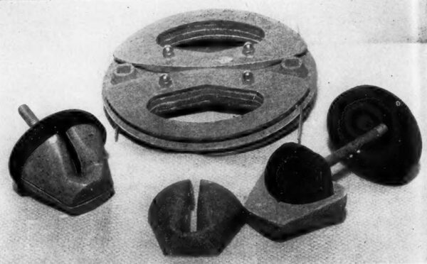
The suspension insulator consists of four parts (See Fig. 1). The weatherhood that provides the dry path is of heavy-wall polyethylene that also serves as a lock ring for the two wire hangers that treat each span and its variable vibrations separately. These two hangers in each insulator transfer the wire vibration to the supporting neoprene rubber core on which they are supported. This neoprene core is molded onto the bolts that are of appropriate length for crossarms and for the single circuit assemblies. This insulator is also used for dead-ending of open wire as well.
The combination long nut is of a high strength insulating material that reverses to three applications of use on single circuit lines, such as straight line, vertical and horizontal dead-ends.
| |||
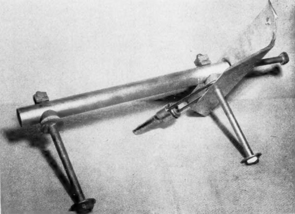
| Fig. 2. the Crossarm Standard Assembly. |
The transposing plate is designed to transpose the circuit in mid-span in the Topo plan and is also to be used on the crossarm on existing and conventional type of open wire lines (see Fig. 1). It is 10% inches in diameter and 1% inches in thickness. It is identical on both sides and consists of a center base plate with four wing plates that are attached to the center section by means of four bolts equipped with crown nuts for easy wrenching application. The transposing plate is turned into the circuit with one wire on top and the other on the bottom side. Large hand holes are provided for easy turning against tensions of the wire. This plate provides 8 inches of spacing of the wires in the circuit and requires no changes from left to right over transposition. When used in the Topo plan where there are no ties at the suspension insulators, the four bolts are loosened to permit access of the wire into the locking groove of the plate, then the bolts are tightened to lock both wires securely in the plate, which prevents a broken wire from running beyond the plate locations. Raised bosses with elongated bolt holes are provided in the sides of the plate for bolting onto crossarms when used on conventional wire plant.
| |||
| Fig. 3. the Crossam Standard Assembly. |
On our two-wire lines, we have used the transposing plate near the center of each span. This provides stability to the circuit in high-cross winds as its weight of 4 pounds serves as a ballast to effectively reduce vibration at its point of origin in the center of the span. On multi-circuit lines, we have used the standard R-1 transposition scheme with the transposing plates in the center of the span. The weight of the plate causes the transposed circuit to sag slightly below the adjacent straight through circuit and prevents the possibility of mid-span wire contact. We have even tried, by manual methods, to cause such mid-span contact, without success.
Crossarms are attached to the pole by means of two through bolts 14 inches apart and supported at right angle to the pole by a 3-inch angle iron that supports the underside of the arm for a distance of 18 inches (see Fig. 2). This angle section is, in turn, supported by a 1% inch pipe section that is also 18 inches in length and is bolted to the hole with the two through bolts.
This assembly is designed to leave the entire under-arm area free for the suspension insulators, as well as extend substantial strength to crossarm. It also has provisions for a fuse action in the event of sudden unbalanced loads that normally would break the crossarm or the pole by bending of the pipe section betweenthe two through bolts. This brace is also equipped with two guying grommets of durable insulating material that also serve as shims between the pole and the pipe section. The top grommet is located directly under the crossarm which permits side guying directly to the load on the arm and its insulating material prevents grounding of the pole line hardware. Additional guys may be placed on the second grommet located on the bottom through bolt.
The crossarms may be ordered bored with 11/16-inch holes that provide variable spacing of the wire at 8 inches, 12 inches, 16 inches and 24 inches. This combination permits side arming up to 24 inches without additional bracing, other than the above described support assembly.
All wire under the Topo plan is placed at the recommended tensions of the wire manufacturer. A dynamometer calibrated to at least 1,000 pounds and roller bearing eveners are imperative tools to the proper placement of wire on this plan (see Fig. 3). These tools insure proper and identical tension to both wires of the circuit which is of utmost importance.
| |||
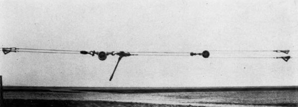
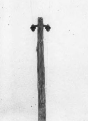
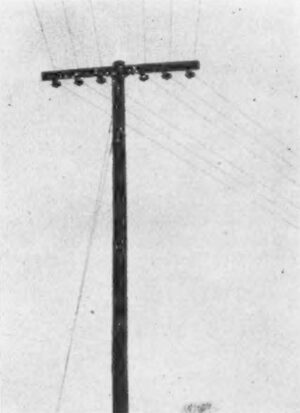
| Line View of Single Circuit Plant. |
| |||
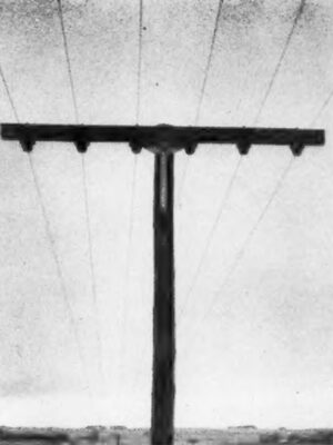
| Three Circuits on Crossarm Plant. |
| |||
| Six-Wire Dead-End on Truss Back-Arm Using the Standard Insulator for Dead-Ending Application. |
| |||
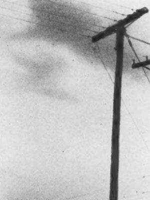
| Corner Construction With Sufficient Angle to Use the Combination Long Nuts and the Single Circuit Assembly Insulators Mounted on the Sides. |
The value of the wire equalizers is that both wires are of identical tensions, therefore, shorts in open wire are virtually an impossibility if caution is used in stringing operations. We have tried unsuccessfully to short-out these circuits by pulling the wire down at the transposing plate locations and twisting the circuit several times, then releasing it to its normal position, but within seconds the circuit clears itself of the short. This is attributable to two conditions; first, the identical tensions of both wires of the circuit, and, secondly, the wider separation of the wire at the points of support, as compared to the 8-inch separation of the wire at the transposition plates. We have purposely dropped trees, limbs, and old poles with crossarms attached, in an effort to simulate a natural attack on these new lines and we have yet to experience the first short, cross, open, or the first case of trouble on our new lines.
| |||
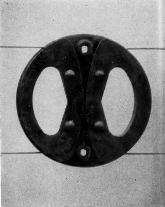
| Transposition Plate. the Open Wire Circuit is Locked Under the Raised Wings of the Plate Which Prevents the Wire From Running in the Event of An Open. |
| |||
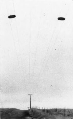
| Line View of Typical Three-Circuit Plant With Transposition Plates. |
| |||
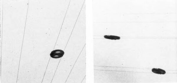
| Left: Center Circuit Transposed on the R-1 Scheme. Right: Outside Circuit Transposed on the R-1 Scheme Showing How the Weight of the Transposition Plates Prevents Mid-Span Contact Between Circuits. |
This report is made from our experience with this type of plant which we built in 1956. At this writing we have started our 1957 construction program on the Topo plan in spite of deep frost conditions, because the economies that we have experienced more than compensate for the additional costs encountered in winter and early spring construction activities.
*Earl Seeman is owner and Milton Seeman is plant superintendent of the Jasper Telephone Co Jasper Minnesota.
·
·
. . . [illegible text] . . .
