[Trade Journal]
Publication: The Electrical Engineer
New York, NY, United States
p. 370-371
The Lauffen-Frankfort Electric Power Transmission
We have on several occasions described some of the methods and apparatus employed in the transmission of electric power at high potentials from Lauffen to Frankfort, a distance of 112 miles, and our correspondent, Prof. R. O. Heinrich, has also described in detail the electrical system of transmission employed. There are some additional details, however, of this installation which our readers will be interested in, as they bear directly upon the question of the possibility of the transmission of alternating currents at high potentials. The dynamo machine situated at Lauffen generates a three-phase alternating current, each component of which has a pressure of 50 volts and delivers 1,400 amperes. From this machine the currents are at first led to switchboard, which is illustrated in Fig. 1 (not shown here). This is equipped in the usual manner with the necessary measuring instruments, safety cut-outs and switches. From the switchboard the current is led to the transformers, which increase the potential from 50 volts to 30,000, the ultimate voltage capacity of the transformer. These transformers are placed in oil in order to obtain sufficient insulating power for the high-tension currents.
From the transformers the high-tension currents are conducted to the lines, three bare copper wires of four millimeters diameter. The line consists of poles eight meters high, placed about 60 meters apart, the number of poles employed for the whole distance being about 3,000. The copper wire employed has an aggregate length of about 530 kilometers. It has been furnished by the firm of F. A. Hesse Sons, who, in order to further this important work, have loaned it for this occasion at a very small compensation.
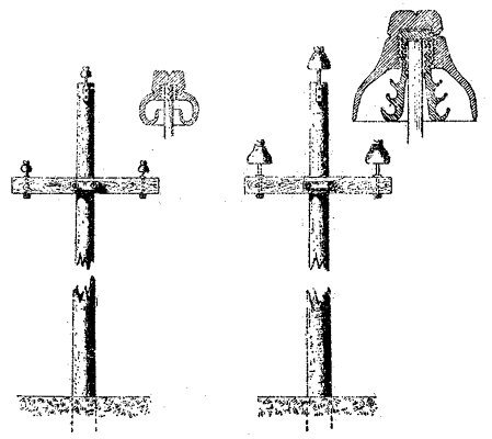 |
| Figs. 2 and 3. - Poles and Insulators. |
The most important point evidently in this undertaking is the proper insulation of the line. The Allgemeine Elektricitats-Gesellschaft and the Machinenfabrik Oerlikon, besides furnishing the generator, motor, and auxiliary apparatus and transformers, also bore the expense of the insulators - no small item. These were manufactured by the firm of H. Schomburg & Sons, Berlin. Two types of insulators are employed; for a part of the distance that shown in Fig. 2 is used, giving but a single layer of oil between the insulator and the support, while for about one third of the distance the type shown in Fig. 3 is used, lack of time preventing the equipping of the entire line with the latter type of insulator; the total number of insulators reaches 9,000.
At Frankfort the high-tension circuits are conducted to three oil transformers of the type illustrated in Fig. 4 (not shown here). One of these, which was constructed by the Maschinenfabrik Oerlikon, reduces the potential of the line to 100 volts with a corresponding increase in the current strength. This transformer feeds a battery of 100 incandescent lamps arranged in the shape of an illuminated sign, and consumes about 100 h.p. that is, half of the power transmitted. The remaining part of the current, a trifle over 100 h.p., is converted by two transformers made by the Allgemeine Elektricitats-Gesellschaft, and also reduces the tension to 100 volts. These transformers, as will be seen, consist of three cores having the low potential secondary wound next to the iron and surrounded by the high potential primary, which is built up in sections to secure more thorough insulation. The secondary current from these transformers drives the large electric motor of the Allgemeine Elektricitats-Gesellschaft, which is illustrated in Fig. 5 (not shown here), as well as a number of smaller motors also built on the rotary phase system. The large motor has current led to it through six circuits, and makes 600 revolutions per minute. It is connected directly to a centrifugal pump, built by Brodnitz & Seydel, of Berlin, and raises the water for a large artificial waterfall to a height of 10 meters.
