[Trade Journal]
Publication: The Electrical Engineer
New York, NY, United States
p. 501
HEWETT'S IMPROVED FORMS OF THE POROUS OIL INSULATOR
By R. J. Hewett
In The Electrical Engineer of March 30 was given a description of a porous oil insulator invented by the writer and designed specially for insulating trolley wires placed in open conduits. The process of development has produced improved forms of insulators composed of a combination of porous and non-porous insulating materials.
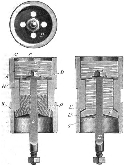 |
| Figs. 1, 2 and 3. - Hewett's Improved Porous Oil Insulators. |
Figs. 1 and 2 of the accompanying engravings show respectively a sectional elevation and plan of one of the improved forms. The shell, or outer portion, is composed of a tube of well-glazed porcelain, glass or hard rubber A. Into the lower part of the smaller diameter of the tube is placed a porous plug P of wood, porous earthenware or other suitable porous material. This plug forms a bottom to the oil chamber C C. The plug P is pressed upward against the beveled shoulder N by means of the shank E, which passes through the plug and then through the perforated plate D, and is tightened up by a nut G. The perforated plate is sustained by the shoulder H. The plan view shows the perforated plate, the object of the perforations being merely to unite the upper and lower oil chambers into virtually one chamber.
The oil chamber C C is filled with an insulating oil, such as paraffine, which percolates through the porous plug P and runs off on its conical underside to the inner surface of the porcelain tube, down which it flows in a continuous film to the edge, where it drips off.
A groove round the centre of the insulator is provided for receiving a clasp, by means of which it can be attached to the side of the conduit or manhole. A wire holder is attached to the lower end of the shank E. The porous plug P is composed of fine-grained wood, thoroughly seasoned by a special process which drives out all air and resin and thoroughly shrinks the plug so that no further shrinkage can occur.
In Fig. 3 is shown another form of insulator, in which the porous part is reduced to still smaller dimensions. The bottom of the oil chamber C is composed of a disc of non-porous material I, through the centre of which passes the shank E. A washer of felt L2 is placed between the shoulder S of the shank and the disk I. Another porous washer L1 is placed between the beveled shoulder of the tube and the edge of the disc. The oil percolates through these two porous washers and runs down on the surface of the disc and bell as in the other forms. By adjusting the nut G the compression on the porous washers can be varied and the quantity of oil fed through can be regulated. The cap J serves as a covering for the oil so as to exclude dust, etc.
