[Trade Journal]
Publication: The Electrical Engineer
New York, NY, United States
vol. 20, no. 377, p. 84-86, col. 1-2
LONG DISTANCE TRANSMISSION AT 10,000 VOLTS.
(THE POMONA. PLANT.) (1) I.
BY GEORGE HERBERT WINSLOW.
THE Pomona plant was installed in the summer and fall of 1892 for the San Antonio Light and Power Company, of Pomona. Cal. It was increased in the following spring, and early last year the capacity of the plant was doubled by duplicating the entire equipment. At the present time, when the plant has been in regular operation for more than two years, and its complete success has established confidence in the successful outcome of many similar projects of greater magnitude, it seems fitting to present a careful description of the entire installation. The electric plant was installed under the personal direction of the writer, as electrical engineer, who presents many of his personal observations on its construction and operation.
 |
| Figs. 1 and 2. |
The plant is used to transmit energy from a waterfall to substations at Pomona, 13-3/4 miles distant, and San Bernardino, 28-3/4 miles distant, from which points it is distributed for incandescent and arc lighting. It consists of a Felton water power plant and a Westinghouse alternating current transmission plant in which generators supply currents to sets of raising and lowering transformers operating at 10,000 volts, and delivering current to the local circuits at 1,000 volts.
The water power for this plant is derived from the San Antonio creek, which is chiefly supplied by the melting snows and the rains on San Antonio Mountain. Side canons, however, also furnish some water.
At the lower end of the valley a sharp ridge extends eastward from the side of a neighboring mountain, from which it originally split off, and blocks up the valley except at a narrow place at which bed-rock is exposed and through which the stream plunges suddenly downward at least 90 feet between precipitous walls of rock, forming the San Antonio Falls. To utilize this fall, part of the water is diverted by a dam about 200 feet above the falls into a canal which conducts the water to a tunnel passing through the ridge. At the other end of this tunnel the water enters a large pipe leading to the power-house, which is located 412 feet below the level of the outlet of the tunnel.
The pipe is of sheet steel, double-riveted throughout, and was delivered on the ground in sections having a length of 11 feet 6 inches. These sections consist of four sheets each three feet long. The diameter of the pipe up to within 450 feet of the powerhouse is 30" with the exception of the length which connects it to the sand-box at the top of the pipe, which length is considerably expanded, so as to allow the water to flow slower on entering, and thus to reduce the entrainment of air. Near the powerhouse a "reducer" is inserted in the pipe to reduce the diameter to 24", and this size is maintained from this point to the powerhouse. The pipe was designed to carry 2,000 miner's inches of water (measured under a head of 6 inches), without unnecessary loss by friction. The capacity is equivalent to 50 cubic feet per second, or 1,882 H. P. at 890 feet effective head, assuming a wheel-efficiency of 85 per cent. This is nearly three times the power for which the present station was built, but the extra capacity of 1,000 horse-power obtained by increasing the capacity of the pipe costs so little when compared with the cost of building an entire new pipe-line, that it is much more profitable to lay the larger pipe in the first place, if sufficient water can ultimately be developed to utilize the added capacity.
The thickness of the pipe is increased as it nears the powerhouse to provide for the increase in pressure in the lower parts. At the first bend it is made greater than that of the sections above it on either side, because the pressure on it is greater. After passing the second air-valve, first No. 10 and then No. 8 steel is used, the latter size being continued to within a short distance of the power-house. The last few lengths are of No. 6 steel.
The horizontal distance between the mouth of the tunnel and the power-house is 1940 feet, and the difference in level between the tunnel and the floor of the power-house is 412 feet. The total length of the pipe, following the line, is 2,370 feet.
The sections of pipe as received from the makers were coated with asphalt both inside and out, and parts of this coat were of course scraped off through rough handling. After the pipe was laid and jointed, a man went through it and painted the joints with hot asphalt to prevent rusting.
In order to protect the pipe from the great changes in temperature which occur in the mountains between midday and mid-night, earth and loose rock were placed around and on top of the pipe without any tamping, and where enough earth could not be conveniently obtained, brush was cut and piled on the pipe and covered with a light layer of earth and rock.
The lower end of the pipe is closed by means of a 24 in. Ludlow gate-valve, which is bolted to a cast-iron flange riveted to the end, of the pipe.
The stem of the valve is geared to a small hand-wheel, partly on account of its weight, but chiefly in order that the gate may not be shut too quickly, as otherwise the pipe would be subjected to severe strains, resulting from suddenly checking the velocity of the column of water. The gate is connected by a tapering pipe of steel to a horizontal, cylindrical steel receiver 20 feet long and 42" inside diameter, from which the water is distributed to the wheels.
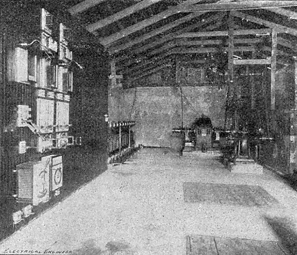
Two tapering cast-iron pipes (a large and small one) are bolted to the lower side of the receiver at an angle of 30 degrees. These pipes conduct the water from the receiver to the under sides of two independent Pelton water wheels, which drive an alternating '0, current generator and its exciter. (See Fig. 1.)
The pipe running to the generator wheel is provided below its valve with two nozzles cast in one piece and attached to the valve by means of a limited ball-and-socket joint, which permits them to be moved vertically to deflect the water.
A set of tips of different diameters is supplied with each nozzle, so that the size of the jet used may correspond to the maximum load and thus unnecessary waste of water be avoided. The tips for the generator-wheel range from 1-1/2 to 2-1/2 inches in diameter, while those for the exciter are from to inch. When tips are used of the proper size for the full load there is no need of throttling at the full load, and, therefore, no loss from this cause; and with the deflecting nozzle there is no waste of water at fall load, so that for full load the two arrangements are equally good. This is not, however, the normal condition of operation of a lighting plant, for in such a plant each dynamo is driven by a separate wheel, and the load is constantly changing, so that here the deflecting nozzle has the advantage. The deflecting nozzle is also to be preferred under high heads, to avoid the risk of straining the pipe by suddenly checking the flow of water, as would be necessary with a throttle valve if the entire load were suddenly thrown off.
 |
| Fig. 3. |
The speed of the generating-wheel is maintained constant for different loads by deflecting the stream. This is done by raising or lowering the deflecting nozzle from the dynamo-room by means of a lever fixed to a shaft which passes through the wall and carries a short lever connected to the nozzle by a link. The weight of the nozzles is counter-balanced by a movable weight on a horizontal lever-arm fixed to the shaft. The change of position of the nozzle is made automatically by the use of the Pelton differential governor. The arrangement for governing is briefly as follows: The generator is geared to stop itself by turning the water off the wheel, and the source of constant speed is geared to speed up the generator by a contrary action. These two actions neutralize each other when the generator-speed is the same as the fixed speed, but when either preponderates the difference acts. Thus an increase in generator speed will act to stop the generator, while a decrease, by making the fixed speed predominant, acts to speed up the generator. The governor consists, in part, of two similar miter-wheels which are mounted upon pulleys and placed face to face, loosely, upon a horizontal shaft, and are driven at equal speeds in opposite directions, one by the generator shaft, and the other by the exciter shaft. The speed of the pulleys is 200 R. P. M. In Fig. 2 it will be seen that between these wheels, and at right angles to the supporting shaft, there is fixed to the latter a cross-bar, carrying two miter-wheels, one at each end, which mesh with the two oppositely revolving miter-wheels first mentioned. The result is, as long as the two outside wheels are revolving at the same speed the two central wheels will merely revolve upon their axis without tending to move in either direction the arms upon which they rotate. Now, if the generator-speed increases, the corresponding side of each central wheel will have to travel faster forward than the other side travels backward, and the difference between these two movements will result in a movement of the central wheels in the direction of a faster wheel, and the cross-bar will consequently move the same way. The shaft to which the cross-bar is attached will, of course, turn with it, and as this carries a pinion meshing in a toothed quadrant connected to the lever which controls the nozzles, the stream will be pulled away from the wheel until the generator speed falls to its normal value.
In order to avoid see-sawing it is the practice in this plant to reduce the head every morning during the light load. This is readily done by opening the extra 4" relief-valve and allowing water to escape until the pressure has gone down to that corresponding to the desired head. The valve is then set tentatively until the pressure remains about constant, when the final adjustment is made by partly closing the valve on the generator-wheel pipe. Meanwhile the governor throws more and more of the stream onto the wheel to compensate for the decrease in head, and the see-sawing stops.
To start the plant, the governor ratchets are first disengaged and the exciter is brought to a moderate speed; the generator is then started and its field is charged; it is then brought to about three-fourths of its full speed, and the speed of the exciter is then slowly increased until the cross-bar on the governor ceases to move. At this moment the ratchets are thrown in, and the governor takes charge of the generator speed. The speed of the exciter is now slowly increased to its full value, which of course brings the generator to full speed. The speed of the exciter-wheel is regulated by a small throttle-valve, the changes in the position of which do not have any noticeable effect on the pressure in the pipe, owing to the small size of the jet controlled.
The power house is 66 ft. long by 30 ft. wide, and has walls 12334 ft. high. The walls, which are of concrete, were all built by tamping concrete in a space between temporary wooden walls forming a mould, a few feet of wall being built at a time, and the planks then loosened and raised to the height of the next section, the walls being thus made at the least expense for timber.
| |||
| Generating Station, San Antonio Light and Power Co. |
The station was built to accommodate four 120 K. W. 7,200 alternation, 12-pole, single-phase Westinghouse alternators, with their full complements of raising-transformers and switchboard apparatus, and two exciters. The first installation consisted of one generator with one 90 ampere 125 volt "I" exciter, capable of exciting the four alternators, and of 126 K. W. capacity of oil transformers in 21 units of 6 K. W., one of those units being kept reserve.
Several different methods of connecting the raising and lower-transformers were given careful consideration, the test of ac-use favoring a series connection for both primary and secondary coils of both sets of transformers, a plan which has proved to be thoroughly reliable in its practical operation at the Westinghouse plant at Portland, Oregon. It was however decided, in order to be able to change the initial pressure on the line in case of accident to any of the converters, to connect the primary coils of the raising transformers in multiple to the dynamo, put the line coils all in series with the line and with a similar set of coils in the lowering transformers, and connect the other coils of the latter in multiple to the distributing circuits.
| |||
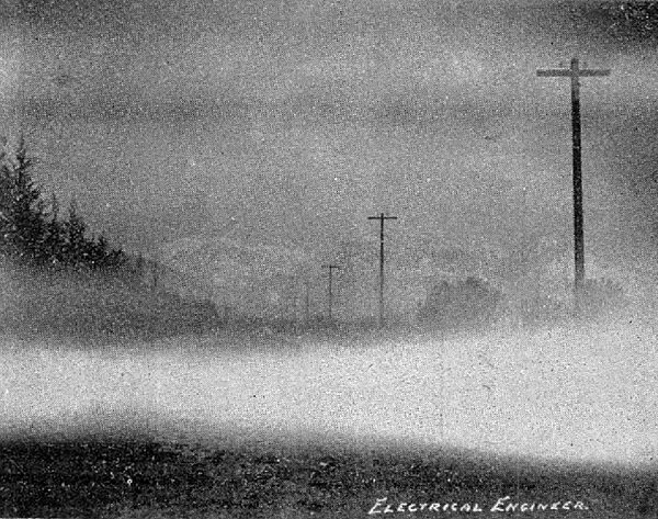
| Pole Line Through San Antonio Canyon, Pomona Power Transmission. |
The next question was what size of transformers should be used. Many small transformers meant less cost per unit for repairs, greater facility of handling, and greater flexibility in case it were desired to change the voltage on the line. Their use, however, also meant greater first cost, more complication, and somewhat lower efficiency, but these points were outweighed by the former, and a transformer unit of 6 W. was chosen. Each transformer is contained in a cast-iron box provided with vertical outside ribs, which serve to stiffen it, and also to cool the oil with which the box is filled, and which entirely covers the transformer. The box is covered by a cast-iron lid, which has conducting and radiating ribs both outside and in, the inner ones dipping into the oil at its hottest part and helping to cool it.
It also has an oil-gauge to show whether the tops of the coils are completely covered without having to raise the lid. The boxes are supported upon a substantial timber frame, upon the top of which two iron bands serve incidentally to protect the wood, but chiefly to metallically connect the boxes to each other and to the earth, in order to dissipate the static charge received by the boxes, which is very unpleasant. The core of the transformer is connected to the box by a copper strip fastened around a block of wood upon which the core rests in the box, and to provide against the danger which would result from accidental connection between the primary and secondary coils, an insulated sheet of copper is placed between the latter and close to the dynamo-coil, and is connected to the core by a tongue which is stuck between the plates.
The line-coil of No. 7 B. & S. gauge wire, is inside the dynamo coil, and is kept everywhere at a distance of one-half inch from the latter, the ground plate, and the core, by walnut blocks boiled in paraffin, between which ample openings are left for circulation of the oil. The ratio of transformation is 1000 to 450, so that in a bank of twenty transformers the dynamo pressure required for 10,000 volts on open circuit is 1,110 volts, and on full load about $ per cent, more than this, or 1140 volts. The space between the 1,000 volt coil, and the core, is one-eighth of an inch. The terminals of the line-coils are brought up through the oil in mica-fibre tubes passing through heavy glass bushings held in paraffined wooden blocks which are attached to the sides of the boxes. The 1,000 volt terminals are similarly supported, but without glass bushings. The transformers are all connected in multiple to the dynamo-circuit, which is supported directly above them on a light pine framework, which also supports the fuse-blocks. The latter are single-pole, and the fuse passes through a hole in a marble block, the object of so confining the arc being to blow it out by its own force. Only one fuse is used on each transformer. The secondary or line coils are all connected in series by U-shaped insulated wire connections which may be readily detached when making periodical tests for insulation of terminals, and which are entirely independent of the frame-work supporting the dynamo circuit. Accidental &intact with the exposed connectors is prevented by the framework above mentioned, and there is an inflexible rule that the high tension side of the transformers shall not be touched under any circumstances whatever, while the dynamo is running.
Clark's insulation is used on all wires connected to the trans formers and to the dynamo, and the terminal wires of the full bank, which must often be disconnected for testing, are further insulated by heavy glass tubes at points where they might conic in contact with other wires. All other transformer wires are sup ported upon double petticoat glass insulators, and all dynamo wires upon porcelain knobs.
| |||
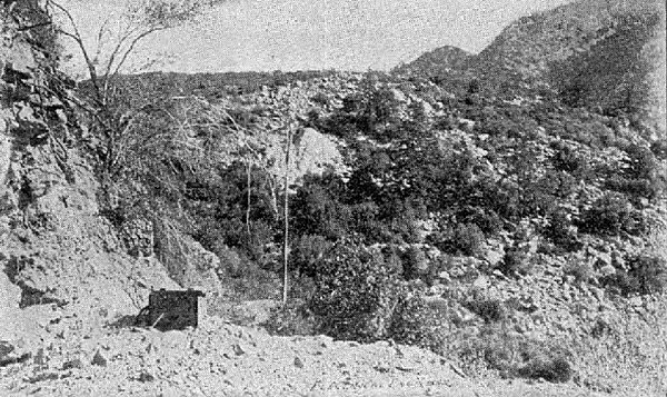
| Outlet of Tunnel, Pipe Line in Centre of Picture. |
The switchboard is of narrow red-wood boards, tongued, grooved and beaded, nailed on a framework of yellow pine, the latter supported on porcelain insulators to keep it dry. The switchboard outfit for the one generator and one exciter consists of two 120 amp. fuse blocks, field rheostat with a 25 amp. n. P. field switch with fuses, one 150 amp. ammeter and a 200 amp. D. P. jaw-switch. From this switch the current passes to two 4-dynamo, marble switch-panels which are connected in multiple to the dynamo, and are each provided with two pairs of contact plugs. By means of these panels and of the two 200 amp. dynamo-changing switches below them, any feeder can be operated from any dynamo which is connected to the switch-panels. Between each panel and its switch is a pair of 65 ampere Wurts shunt-wire fuse-blocks, each provided with an extra fuse and shunt which can be connected by inserting a plug should it be desired to double the fuses during the run, on account of overload or of weakness in the fuse. The remaining instruments on each feeder are a voltmeter, a No. 1 switch-board converter and a 150 amp. type "E" compensator. When both feeders were run from one alternator, one voltmeter was connected to the generator and the other to the feeder, and in this way the amount of compensation could be watched.
| |||
| Bank of 10,000 Volt Transformer. |
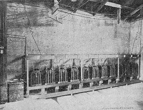
The oil-transformers were tested before shipment with 20,000 volts between the line-coil and the core and were then taken out of the oil and boxed. In order to expel any moisture which might have been absorbed by the insulation of tire coils or have condensed on the cores during their long journey, the transformers were connected in two banks of ten each, the line-coils of each set being connected in series to the generator, which was run at a reduced speed, and the secondary coils each short-circuited on itself. The coils were thus gradually heated to a point somewhat above the boiling point of water, which at that elevation was about 201 deg. F. They were kept at this temperature for a short time and then paraffine oil of a special grade ("Diamond") was poured slowly into the boxes at the edges so that the coils would begin to absorb oil at their lower ends, and thus drive upward the air and volatile gases occluded by the insulation. The transformers were then again brought to their former temperature, which caused expansion and partial expulsion of the air remaining in the insulation. Some of the air would however collect under the insulation at the top of the coils, and had to be freed by mechanical agitation, produced by stirring the folds of insulation or by pounding on the boxes. The heat caused volatilization of some of the lighter elements of the oil, these coming to the surface as bubbles, just as the air did at first, and the agitation was kept up at intervals until bubbles from this cause also were entirely eliminated.
The 20 transformers were then connected as they would be when in regular use and the two terminals of the line-coils, which were to give 10,000 volts, were connected in series with one hundred 100-volt lamps, which were then brought to full candle power, showing that the transformers were all in good condition. A similar test was then made at Pomona at the end of the 14-mile transmission line running to that place, after which the transformers there were prepared for work in the same way as at the power-house, except that the grouping and initial voltage were changed.
1. Abstract of a paper read before the Amer. Inst. of Elec. Engrs., Niagara Falls, June 28-80, 1895
