[Trade Journal]
Publication: Western Electrician
Chicago, IL, United States
p. 131-132, col. 1-3
High-tension Insulators
By R. Scott
Wherever circuits of 20,000 volts or greater are employed in the transmission of electrical currents it is necessary that the line insulators employed should be of special design and should embody the following factors:
1. Great resistance to arcing between the cross-arm, pin or other supporting part and the conductor.
2. Large superficial area to give extensive surface over which the leakage current may creep.
3. The material employed must successfully resist any puncturing strains which may be developed.
4. The insulator must possess good ability properly to distribute the electrostatic strains developed by lightning or other electrostatic surges.
5. Low radius of gyration to prevent both the breakage of the pin or other supporting member and the insulator.
6. Protection against the precipitation of moisture on all parts.
 |
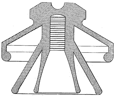
| Fig. 1. Porcelain Insulator for 30,000 Volts or Less. |
An insulator should not be designed for the voltage of the circuit alone, but should be capable of withstanding the overplus voltage which under normal and abnormal conditions is liable to occur. High-tension circuits frequently, without the coincidence of electric strains, develop areas or zones of high-tension surges, these being concentrated upon various parts of the line. Although such surges are electrostatic in character, their exact nature is not understood, but experience has shown that such concentrations of high potential actually exist and effect a disruption of the insulators whose design is such that they cannot withstand this abnormal potential.
Although the natural precipitation of moisture is usually in a vertical direction, it is not best to assume such conditions to exist in practice. For this reason the usual test is to spray water from a hose inclined about 30 deg. from horizontal and spaced about six feet from the insulator, the water having usually low pressure and the nozzle being of such design that the water is thrown upon the insulator in the form of a spray. Using the requisite testing voltage, it is thus possible to test an insulator under conditions even more adverse than those found in practice. Such tests show that the mechanical design or outlines of the petticoats exert a marked influence upon the behavior of the insulators.
To show the relation which should exist between the cross-section of the insulator between the conductor and the pin the following data are given: Taking the specific resistance of copper as 1, the specific resistance of rainwater is about 6,754,000,000, while that of glass is about 1,400,000,000,000,000. This shows that for a given insulation resistance, assuming that water is precipitated upon every part of the insulator, the relation between the superficial area and the cross-sectional area must be very great indeed. This does not take into consideration the depth of the film of water or its average sectional area, but the above figures give a general idea of the relation which should exist between both.
Another important consideration is the ability to withstand the tendency for setting up an arc after a circuit passing a minute current has been formed between the pin and the conductor. This ability depends entirely upon the air space intervening between the pin and the conductor measured around the superficial area of the petticoats, as it is not assumed in this case that the insulation has been ruptured in any way through its section between the conductor and the support. It is necessary in designing that the worst conditions that can be set up in practice be constantly borne in mind. An insulator may be designed which has a large sectional area and large superficial area, but which when operated under one-third of the testing voltage for a certain period of time in a region where large amounts of dust are precipitated upon its entire surface will fail because of the fact that the dust has so reduced the resistance from the conductor to the pin that a slight shower serves to set up a path which starts an arc between the conductor and the pin.
Another important factor which must be dealt with is the phenomenon of resonance, which occurs on lines having a relatively high frequency, such as 66. A test at double the voltage which the insulator is to withstand will result only in showing its capacity for withstanding a certain static potential. The same insulator when placed upon a line having a high resonance factor will fail, due to the concentrations of potential resulting on such a line.
Although the usual conditions of practice do not demand that an insulator be capable of withstanding twice its normal voltage, an abnormal condition may impose upon the insulator an even greater excess for a very small period of time. If such periods are successfully passed over no deleterious effects are produced, but if at such times the insulator should happen to be in such a condition that the disruptive tendency cannot be overcome, then failure will result.
Testing is for one purpose, namely, to ascertain the relative adaptability of insulators for various specific conditions of practical service. An insulator may be of such design that it will withstand a double or triple-voltage dry test, and yet fail at normal voltage in long-continued operation under practical wind-driven precipitation conditions. Usually, however, the successful performance under dry test renders unnecessary a wet test for ascertaining the arcing pressure. The arcing voltage, under conditions of short-circuit, would not produce the same effects in practice, due to the dissimilar conditions of the pin cross-arm and pole and the other insulators. If the system were grounded, the greatest stress on a rainy day would undoubtedly be between the conductor and ground, and with a comparatively low ohmic factor between the pin and ground would result in excessive strain on the insulator. Of course, every system is, in a measure, grounded by the multiple paths afforded by the poles, but as to this effect on the insulators it cannot be determined with any degree of accuracy.
Like some other electrical devices, an insulator embodies a large amount of uncertainty. Its action during long-continued service cannot be predetermined with any degree of certainty or accuracy. It must be a point of consideration to assume a number of conditions that must be accepted as affecting the operation.
 |
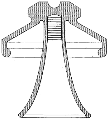
| Fig. 2. Insulator Used in Moisture-Laden Atmosphere. |
The stresses which occur by long-continued variable-impressed voltage may be likened in their effect to the reciprocating stresses produced in the connecting rod of a steam engine. These stresses, when repeated for 300 to 1,000,000,000 times, have about the same strain effect on the weakest parts as that which would occur were the rod bent at right angles and straight again at this particular part, with a radius of two or three times the thickness of the rod. The tendency of long-continued voltage strains, therefore, is ultimately to disrupt the insulator. This fact, therefore, should be in sight when designing any insulator.
It is possible for an operator having some experience to deduct from the performance of an insulator under test its relative integrity when in practical operation. The effects of various stresses and conditions manifest themselves in purring, humming or cracking noises, and partially visible arcing or creeping paths. When the point of visible discharge has been reached, without its being the result of inductive conditions, the voltage may be taken as the limiting pressure at which the insulator fails.
The points to be noted during the process of testing have been recognized as the following, which are arranged in the order of their precedence:
1. The first visible indication of the static brushes or discharges from the lower edges of the insulator.
2. The point at which a heavy discharge leaps from one part to another.
3. The point at which well-defined snapping and crackling occur, with indications of the establishing of general rupture.
4. The point of breakdown or puncture of the insulator.
Although the above points are usually separate and sharply defined, owing to the cumulative effect of the minute breakdowns, the time intervening between No. 1 and No. 2 is usually greater than that between No. 2 and No. 4.
 |
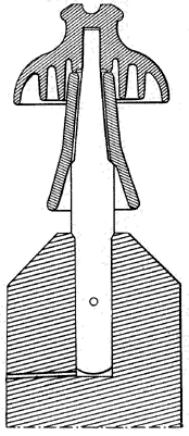
| Fig. 3. Missouri River Glass Insulator for 55,000 Volts. |
Insulator manufacturers are all well aware of the effect of economy in construction.
No part of a high-tension system should require such careful selection of materials as the line insulators, operating as they do under conditions which are most adverse to the transmission of high-tension currents, and which represent in reality the only drawback to increasing the tension to a figure that is regarded at the present time as impossible. In a measure the adoption of the line pressure to the line depends upon the insulation employed.
Economy, while a natural predisposition, should therefore be exercised in every other part of the system rather than on the line. Faulty or "economical-initial-cost" insulators usually manifest themselves in burned-out cross-arms, firework displays (pleasing to the eye but annoying to the company) and dangerous service.
Therefore if a high standard of construction is to be employed, it should commence and continue with the line insulators. As a necessary device a good insulator may be said to be very good, and a poor insulator very poor (and costly).
In Figs. 1 to 5 are shown in section a number of forms of high-tension insulators which represent the result of many years of development in construction. They will serve to show the reader the primary points on which stress is laid by the manufacturer, these points having been outlined in the above description.
Fig. 1 shows a porcelain insulator that has, under normal conditions, been applied to various sizes to transmission systems operating at voltages up to 30,000. This insulator is designed for localities where the natural precipitation is abnormal and intermittent, with average dry atmospheric conditions.
Fig. 2 shows a design used in localities where a humid and moisture-laden atmosphere exists. The outline is such as to give a maximum of creepage surface. Its disadvantage is long radius of gyration, which necessitates the use of very strong pins.
In Fig. 3 the famous Missouri River transmission insulator, introduced by Gerry, is shown. This insulator operates under particularly adverse conditions at 55,000 effective volts. Made of glass, in two parts, its creeping surface is very great. To prevent rotting of the pin by the accumulation of water, the cross-arm or pole is provided with a one-eight-inch vent, as shown. The maximum diameter of the petticoats is 8 15-16 inches and the length of the sleeve eight inches.
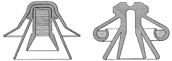
In Fig. 4 is given a section of an insulator which has been largely used in Europe, especially in Switzerland, for voltages up to 60,000. Although but a slight departure from American designs, its special feature is to render dust and vegetable accumulations innocuous.
 |
| High-Tension Insulators. |
Fig. 4. Swiss Insulator for 60,000 Volts.
Fig. 5. Recent Insulator for High Voltages (with Oil Lip.)
Fig. 5 shows an insulator which, while as yet but little introduced, gives a very high superficial ohmic factor. The great disadvantages are difficulties attending manufacture, high cost and uncertainty of behavior of the oil within the internally arranged lip. This represents a modification of the immortal Lauffen-Frankfort system of transmission (110 miles), the first attempt at transmitting energy over a long distance.
