[Trade Journal]
Publication: Electrical World
Chicago, IL, United States
vol. 32, no. 22, p. 557-561
High-Voltage Power Transmission Part I (1)
BY CHAS. F. SCOTT.
Several years ago an investigation of the conditions and requirements incident to the use of high voltages was undertaken by the Engineering Department of the Westinghouse Electric and Manufacturing Company. In this experimental investigation the size of the apparatus and the conditions of the tests were as far as practicable such as would prevail in actual work.
The transformer, the sine qua non of high-voltage working, received first consideration. A design suitable for large sizes was worked out and tested; then high-voltage windings were made. Attention was next directed to the line insulator.
New phenomena were liable to be presented at higher voltages and it was ncessary to determine what they were, also how to meet the requirements which they impose. New forms and sizes of insulators were designed, made and tested to determine the losses which would occur and the limit at which they would break down.
The luminosity and the hissing sound emitted by the connecting wires of high voltage suggested a loss which might be an appreciable addition to that over the surface of the insulators. It was found that a very considerable loss of energy took place between the wires a loss which at high voltages was much in excess of that across the surface of the insulators.
Mr. L. L. Nunn visited Pittsburg at this time and became much interested in this work. He was a pioneer in power transmission, having put in the first large alternating-current transmission plant in this country, namely, that at Telluride, Col., which was designed by the writer and described by him at the general meeting of this institute in 1892. It was proposed that this work be taken up conjointly by the Westinghouse company and Mr. Nunn, and prosecuted on a much enlarged scale, by operating the original motor over a high-voltage line. In a report to the vice-president and general manager of the electric company, dated April 2, 1895, the writer said: "The transformers would be arranged to give a line pressure of 10,000, which is to be increased by suitable steps to possibly 50,000 volts... I regard this as an excellent opportunity to make a thorough and extremely important and valuable test of high-tension working under difficult practical conditions, which our company should take up and carry out as fully as possible." Raising and lowering transformers were made and sent to Telluride, and power for the 100-hp synchronous motor was transmitted at voltages far exceeding any which were afforded for observing the practical operation of high-tension working under severe climatic conditions, and for making measurements. The results of the work were so assuring that the Telluride Power Transmission Company has lately installed a plant which is in commercial operation at 40,000 volts and is now making an increase in the plant. This work has been continued on experimental circuits at East Pittsburg, and some measurements have been made at Niagara.
The work which has just been briefly described was an investigation into an unknown field. It has been progressively and sytematically carried out and it has determined results which were unforeseen, and which are of both theoretical interest and practical importance.
This present paper describes the more interesting and important parts of this work and gives the methods by which measurements have been made and the results which have been reached. A number of points of interest and importance are given with regard to long-distance transmission plants now in operation.
HIGH-TENSION TRANSFORMERS
In 1891, the Westinghouse company furnished transformers for the 10,000-volt transmission to San Bernardino and Pomona. Twenty transformers were used in a set, each giving a pressure of 500 volts and the twenty in series 10,000 volts. The insulation between the coils of the high-tension circuit and other parts of the transformer was secured by allowing a space, which was filled with oil.
The first arrangement of transformers for giving from 30,000 to 50,000 volts was made by using a number of transformers, each giving 10,000 or 15,000 volts. The low-tension circuits of the several transformers received current from an insulating transformer in which there were a number of separate coils, each one supplying a separate raising transformer. An arrangement of this kind was used for obtaining the high voltages in the exhibit of the Westinghouse company at the World's Fair. A large transformer was designed in January, 1894. The output of 200 kilowatts was many times greater that that of any transformers which had been made by the Westinghouse company. The transformer was oil-insulated and was cooled by water flowing through a pipe immersed in the oil. This transformer was pronounced a success, and the type was adopted and has been followed ever since as a standard, except that the water-cooling is employed only on the largest size.
The transformer was then rewound for 40,000 volts, and a somewhat reduced output. It was operated at this voltage for a short time, when it was found that through an oversight the insulation between layers was insufficient. In October the high-tension coils were rewound for 60,000 volts, and the transformer is still in use after many months of varied service and a considerable period of inactivity.
The making of a single large transformer for a very high voltage naturally involved new difficulties. Above 10,000 or 20,000 volts there was an unexplored and uncertain field in the matter of insulation. Material which were commonly used at ordinary voltages might have very different characteristics under the new conditions. Tests were made on materials before the first high-voltage transformers were made, and it has been continued. The large high-tension transformer as made to-day was not designed in a week or a month, but it has been an evolution based upon experimental tests and experience in continued operation. (2)
HIGH-TENSION INSULATORS.
After a high-voltage transformer was constructed, the insulator naturally presented itself as a fundamental factor in transmission. The requisites of an insulator for high-voltage work are, that it shall have a dielectric strength sufficient to prevent the current passing directly through the material, that its dimensions shall be large enough to prevent the passage of current over the outside of the insulator to its support, and that the resistance, both of the material and its surface, shall be sufficiently high to prevent undue loss of energy. In addition to these fundamental electrical requirements are those of a mechanical nature involving strength and convenience. These properties must of course be permanent and not liable to deterioration while in service.
Up to this time very little attention had been given to the manufacture and design of high-tension insulators. There were available for our laboratory tests the glass insulators which we had designed for the 10,000-volt transmission line at San Bernardino and Pomona, Cal.
A much larger glass insulator was made having the so-called "helmet" form, which was probably the beginning of a type which is now quite common. The large glass insulator presented mechanical difficulties in manufacture, and recourse was had to porcelain. An insulator was designed to be under-hung, the top of the insulator being supported in an inverted cup which was to be bolted to the under side of the cross-arm. From the bottom of the insulator a pin extended which was anchored in a hole in the insulator and held the wire below the cross-arm so that the snow which might pile up on the cross-arm would not come near the insulator. The wire, moreover, instead of being supported upon the top of the insulator, where it is in connection with an extended wet surface, would be supported from the part of the insulator which is most protected and the driest.
An interesting evolution then began to take place in the manufacture of porcelain. There were eight or ten steps in this history, in which insulators which were presumed by the manufacturer to be satisfactory were broken down on high-voltage test. Porcelain which presented a beautiful smooth glazed surface was often found to contain internal cracks or cavities which were soon traversed by the current. In other cases bits of pebbles or other impurities were found. In still other cases the porcelain was not homogeneous and was not compact, or the material was porous and absorbed a drop of ink almost as readily as a lump of sugar would do. The effect of this work is seen in the improved quality of material now made by certain porcelain manufacturers who benefited by this experience. It may also be remarked that some of the unpleasant experiences with porcelain insulators might have been prevented if similar preliminary tests had been made instead of employing the more expensive and inconvenient method of testing them in commercial service.
The under-hung form of porcelain insulator, however, did not prove successful nor satisfactory. The insulator was heavy and cumbersome, and no satisfactory method was devised for holding the wire. A wooden pin lack strength, and a metal pin reduces insulation. Moreover, smaller insulators of the ordinary form were found suitable for higher pressures than was anticipated.
Some measurements were made of the losses on the Pomona insulators. Twenty-four insulators were mounted on wooden pins. A wire was run along the tops of the insulators and a second wire connected the pins. The increase produced in the reading of a wattmeter in the primary of the raising transformer when the wires were connected to the high-voltage terminals was taken as the loss on the insulators. The loss at 25,000 volts was about two watts per insulator. This voltage between pin and wire corresponds to 50,000 volts between transmission wires.
LOSSES BETWEEN WIRES.
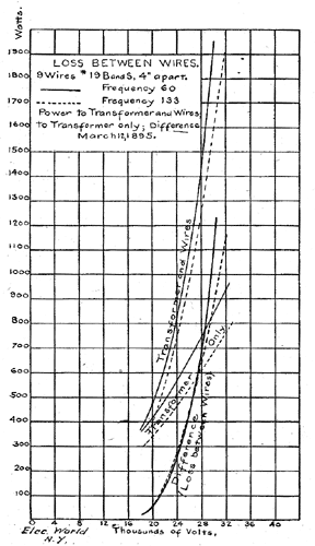
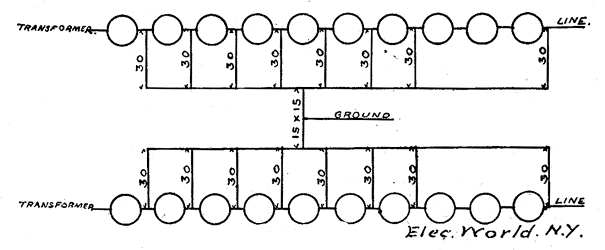
The loss over the surface of insulators was quite small, in fact almost insignificant compared with the amount of power which would ordinarily be transmitted. The various displays of energy about high-tension wires led us to investigate and determine whether this loss was one of importance. In order to measure the loss between wires, eliminating what occurs on the insulators, it was desirable to have a considerable length of wire, to support it without insulators, and preferably to arrange the wires in such a form as to give a considerable loss. Nine wires each 6o feet long were stretched 4 inches apart in a horizontal plane and were held in place by strings several feet in length at each end. The wires were No. 19 B. & S. gauge, 0.036 inch in diameter. They could be connected in various ways, and any pair or pairs of wires could be omitted as desired.
The power supplied to the raising transformer was measured by a wattmeter placed in the primary low-tension circuit. When the load was placed on the transformer, the wattmeter reading increased, and the amount of increase was taken as the power delivered to the load. This method involves certain errors which will be pointed out further on, but on the whole it gives an approximate and fairly correct indication of the power, and is sufficient to show clearly the general form of the loss curves and a number of interesting characteristics.
The first measurements of this loss are recorded February 26, 1895. The first, third, fifth, seventh and ninth wires were connected in multiple to one-terminal, and the other wires were connected to the second terminal of the raising transformer; successively increasing voltages were applied.
The wires began to give a hissing or cracking sound and in the dark began to appear luminous at a little below 20,000 volts. As the voltage was increased the sound became more and more intense, the wires vibrated and became more and more luminous, until at the higher voltages they were surrounded by 'a coating of soft blue light many times the diameter of the wire. Often there were bright points along the wire, probably corresponding to bits of dust or rough places resembling points on the wire. The large room soon became strongly charged with ozone.
 |
| Fig. 1. |
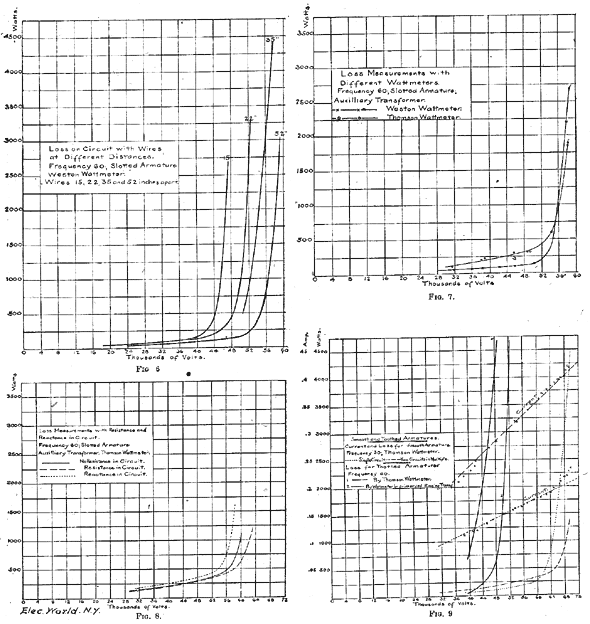
Results of measurements on all wires, alternate wires being connected together to one terminal, and the intermediate wires to the other terminal of the raising transformer, are given in the accompanying cut, Fig. I. Three curves are given for a frequency of 60 periods per second, or 7200 alternations per minute. Two of these curves give the wattmeter readings for the different voltages, one for the transformer alone, and the other for the transformer and high-tension wires; the third curve gives the difference between the two, and therefore represents approximately the loss on the high-tension wires. Corresponding curves are given of tests made at a frequency of 133. The loss in the transformer is less at the higher frequency, but the loss on the high-tension wires is almost the same for both frequencies. These losses are very small below 18,000 volts, but increase rapidly up to 30,000 volts.
As the two sets of tests were made with dynamos having different characteristics they may not accurately represent the relative effects of the frequencies. The difference due to causes other than the frequency are, however, probably small, so that these tests are correct in showing the general relation between the loss and the pressure, and that the loss depends little if at all upon the frequency.
 |
| Fig. 2. |
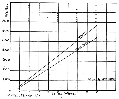
Tests were made with different numbers of wires. In one case the measurements were made with the arrangement described above, in which five wires were connected together and the four intermediate wires were connected to the second terminal of the raising transformer. Two wires at one end were then left off. Two of these were next omitted, leaving three connected to one terminal and two to the other. One of these was left Off, leaving the first and third wires connected together, and the second and fourth also. The first and ninth wires were then connected together, also the second and eighth. As the first and second wires were well separated from the eighth and ninth, the mutual effect between them is negligible, so that the loss in this case may be considered as double that which would be obtained from the first and second wires alone. The results of this measurement are plotted in Fig. 2. The points for both loss and current fall on a straight line and indicate that each additional wire causes a definite increase.
 |
| Fig. 3. |
Measurements made upon wires at greater distances show that the action is considerably less as the wires are separated. The loss is approximately the same at 28,000 volts when the wires are 4 inches apart that it is at 36,000 volts when they are 16 inches apart. The loss for a distance of 8 inches is intermediate.
Other measurements were made, but nothing of further importance was developed. it is interesting to note that within a few days of the first measurements the general characteristics of this loss were determined, namely, that the loss between wires increases rapidly after a critical voltage is reached, that the loss is practically independent of the frequency, that it is much less as the distance between wires is increased. When a loss of 1200 watts was obtained on a total length of 540 feet of wire at only 30,000 volts, the ' important bearing of. this phenomenon upon transmission became very evident. The tests were stopped as preparations were begun for the continuation of the work at Telluride.
TRANSFORMERS AT TELLURIDE.
The original Telluride plants operated at 3000 volts. Both the generator and the synchronous motor were wound for this pressure. Two transformers were furnished for the high-voltage tests, one for raising the generator voltage for transmission and the other for lowering the voltage for the motor. The windings were connected with a number of terminals by which the high-tension voltage could be varied over a wide range up to 60,000 volts.
Coils of similar shape were placed side by side in what is known as the "parallel" form of construction: Each coil had many layers of wire and but few turns per layer, thus securing a small difference of pressure between consecutive layers. The high-tension winding was divided into four similar coils, each designed to give a maximum of 15,000 volts. The individual coils could be differently connected, either in series or in multiple. The low-tension coils were five in number and were provided with loops, by which the number of effective turns could be varied. Three low-tension coils were placed between two pairs of high-tension coils and the two remaining low-tension coils were placed on the two ends. Between the low-tension and high-tension coils metallic shields were placed, which were connected to the ground for protecting the low-tension circuit from danger in case of accidental contact with the high-tension circuit, and also for screening the low-tension circuit from electrostatic induction from the high-tension windings. The transformer was immersed in a case containing oil. The iron and the case of the transformer, as well as the shields between the coils, were connected to the ground.
There was also an auxiliary transformer whose primary was connected across the generator terminals, while its secondary was placed in series with the circuit to the raising transformer, thus either raising or lowering the generator e. m. f. as desired. The secondary had a number of steps so that the voltage could be varied at will.
THE TRANSMISSION LINE
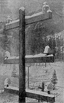
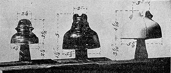
The line extends from the power station near Ames, which is a few miles from Telluride, Col., to the Gold King mill. The line passes over an exceedingly rugged country and has a total length of nearly 2-1/4 miles (11,720 feet). There are sixty-two poles, each carrying three cross-arms, the upper being about 26 feet from the ground. Each cross-arm carries two wires supported by insulators which are designated as follows: Large glass, small glass, porcelain (see Figs. 4 and 5). The large glass insulator is the same as that used on the circuit in the San Bernardino and Pomona plant. The total height is 5 inches and the maximum diameter 5-1/2 inches. The bottom of the insulator stands 1-1/4 inches above the cross-arm. The porcelain insulator is 4-1/14 inches high and 5-7/8 inches in diameter. The bottom is 3-1/16 inches above the cross-arm. The small glass insulator is 3-1/2 inches in height, 4-1/4 inches in diameter and stands 2-1/4 inches above the cross-arm. This insulator is triple petticoat; the other two insulators are double petticoat. The circuits were strung with galvanized iron wire 0.165 inches in diameter, which is No. 8 B. W. G., and about No. 6 B. & S. gauge. Later the circuit on porcelain insulators was changed to No. 6 B. & S. copper wire 0.162 inch in diameter. The measured resistance of one of the iron wire circuits was 66 25 ohms at -7 C.
| |||
| Fig. 4. 50,000 Volts on Large Glass Insulators (Upper Cross-Arm) and on Porcelain Insulators (Lower Cross-Arm). |
RUNNING TESTS AT TELLURIDE
The first tests were qualitative rather than quantitative. It was uncertain what phenomena might accompany the operation of a long line at high voltages, and the pressure which could be used on the insulators was matter to be determined. The first thing was to find what would work; measurements could be made afterward. A high voltage was placed on the transmission line, sometimes transmitting no power and at other times operating the 100-hp synchronous motor. In December, 1895, the motor was operated at 25,000 to 33,000 volts for several days. In January, 1896, 45,000 volts was used continuously for over a week, and beginning with the latter part of March a continuous run of thirty-seven days was made at 50,000 volts. "Some very severe conditions of weather were encountered during this time, very high gales of wind prevailed, the air was filled with clouds of dust; part of the time the snow which fell was quite damp and during the last few days of the run there was some rain. At this voltage the wires were plainly visible at night and the characteristic hissing of high-tension currents could be heard several hundred feet. No lightning arresters had been installed up to this time and the cause of the shut-down was damage to the raising transformer, caused by lightning. Lightning arresters were installed. The lightning season commenced about June 1. During the latter part of June lightning discharges over the arresters were very frequent. At this time we were limited to a running voltage of about 34,000 volts, as there were not enough arresters to permit of increasing the voltage. No trouble whatever was had with the lightning protection. Discharges were frequently seen crossing the arresters and during two or three days in the early part of the season discharges occurred at intervals of a few seconds for several hours. Enough arresters were afterward obtained to run at 45,000 volts, but the lightning discharges were much less frequent."
| |||
| Fig. 5. Insulators Used in High-Tension Tests at Telluride. |
Some measurements upon the line were made by determining the power given to the raising transformers when the lines were connected and when they were disconnected. These measurements showed that the loss due to the line is small below 45,000 volts, but increases rapidly when about 50,000 volts is exceeded, and reached 16.4 kilowatts at 59,000 volts. The results up to 52,000 volts are given in curve 2, Fig. 9. Curve 1 in this figure is the loss on the same circuit measured a year later by a different observer using a different method. At the maximum loss shown there is a difference of only 8 or 9 per cent. in e.m.f. for the same loss on the two curves.
The record of the operation of this line at 50,000 volts for over a month is of very great interest, as it is a practical demonstration of the feasibility of operating a line at 50,000 volts, a pressure four or five times as great as any which had been in general commercial use. Mr. V. G. Converse had been up to this time closely associated with this work. He had much to do with the design and construction of the high-tension transformers and insulators, tests upon losses in lines made at the Pittsburg laboratory and the tests at Telluride.
 |
MEASUREMENTS AT TELLURIDE
The work at Telluride was then taken up by Mr. R. D. Mershon. The facilities for experimental work were increased and instruments were provided for carrying on the tests. Mr. Mershon found peculiar difficulties in making exact measurements of the power to the circuit. A wattmeter in the low-tension circuit of the raising transformer led to errors under the conditions which prevailed. Some very able and painstaking work was displayed in detecting the error and overcoming it with the facilities at hand and the facilities were none too plenty in the heart of the Rocky Mountains for making measurements which would tax the resources of almost any laboratory. The apparatus used introduced a disturbing influence in the circuit, which, however, could be measured and eliminated. On the other hand, a wattmeter for measuring power on a high-tension circuit must accommodate a very high voltage and a very small current. As the charging current to an open line is usually very large in proportion to the loss current, the error of the instrument is very sensitive to slight variations of phase in the shunt current. (A description of the instruments and the methods used is given in an extract from the report of Mr. Mershon at the end of the author's paper.) The result of the measurements and the conclusions are given partly by extracts from Mr. Mershon's report, and partly in abstract.
RESULTS OF MEASUREMENTS.
"The results of measurements taken are embodied in curves.
"In every case the measurements were taken upon an open-circuited linein no case upon a line which was transmitting power. The line losses obtained are therefore a combination of those occurring between the line wires and the very small I2 R loss in the wire itself due to the charging current of the line.
"Measurements taken with the Weston wattmeter include the loss in the high-tension coil of the power transformer due to the currents applied to the line. This loss is in general small and in the following ' curves corrections have not been made for it. Curves taken with the Thomson wattmeter require no such correction.
"There is an additional correction which may be made in the case of those curves whose voltages were obtained from the raising transformer. This correction arises from the fact that the action of the capacity current taken by the line, in connection with the series reactance of the transfornier supplying it, is such as to make the voltage impressed upon the line somewhat greater than that obtained by the ratio of the transformer winding. The measurements taken to determine the amount of the error in voltage show it to be small.
"There were two generators used. One was that regularly running and supplying power to the power circuits of the Telluride Power Transmission Company. It is a 600-kw, 22-pole, quarter-phase machine, delivering 500 volts at a frequency of 60, or 7200 alternations per minute. Its armature is of the slotted type and is wound with copper bars. In the notes this generator is designated as 'Slotted Armature.'
"The other generator is one whose field is that of the 100-kw toothed armature machine, originally sent out as a part of the first Gold King transmission plant. It has twelve poles and as originally run operated at 3000 volts and 10,000 alternations. There are two armatures for this machinea surface-wound armature, designated as 'Smooth Armature,' and a toothed armature, designated as 'Toothed Armature.' "
A set of measurements was made for comparing the loss on the three circuits supplied respectively with large glass, small glass and porcelain insulators. The curves are very nearly identical and correspond very closely with the right-hand curve in Fig. 6. "There was a heavy wet snow on the ground and the cross-arms at the generating station and more or less snow all along the line, that at the further end being dryer than at the generating station. There was more or less snow falling during the measurements, and this accounts for a wide variation of the points taken' at the high voltages, as falling snow renders the wattmeter reading very unsteady, the unsteadiness being such as one might expect if from time to time there was a discharge between the wires. This unsteadiness does not seem to be as great in the case of falling rain as in the case of falling snow."
A series of measurements was made to determine the connection between the loss and the distance between wires. "As at that time it had not been fully demonstrated that the loss was not affected by weather conditions except there was precipitation, changes in distance between wires were made upon one circuit, while the distance between wires on another circuit was maintained always the same, and the latter was used as a reference circuit when a change in loss was observed."
The several curves have been plotted together, due correction being made for the slight difference in the loss in the reference circuit, which probably resulted from slight differences in the precipitation when the curves were taken. The distance between the wires in the several tests was 15, 22, 35 and 52 inches respectively. The results are shown in Fig. 6. It will be noted that the loss is much greater when the wires are close together and that the curve begins to ascend at a lower voltage.
The loss curves in Fig. 7 were taken on one of the circuits, first with the Weston wattmeter and then with the Thomson wattmeter. The Weston wattmeter was not in circuit when the measurements with the Thomson wattmeter were taken. As an additional check, the readings were taken on each of the wattmeters of the loss occurring in the shunt resistance; of the Thomson wattmeter the results were in practical agreement with each other and with those obtained by calculation. The discrepancy in the results obtained on the two instruments when measuring line loss will be referred to later.
A set of comparative readings was taken on one of the circuits and on a dummy circuit, identical with the main circuit, as regards kind and number of insulators and the size of wire, but only 6o instead of 11,720 feet in length. The results show that the loss on the two circuits is practically identical up to about 50,000 volts, which is the part of the curve below the bend. The losses agree closely with those shown in Fig. 6. At higher voltages the loss on the dummy circuit increased slightly, indicating that the loss was of the same nature as that at a lower voltage. The agreement of the loss on the two lines at low voltage (i. e., below the bend in the loss curve) indicates that this loss was over the insulators. The great increase in loss on the long line at high voltage indicates that the loss was due, not to the insulator, but to the line.
Measurements were made with resistance between the generator and the raising transformer, then with reactance and then with neither resistance nor reactance. The results are shown in Fig. 8, and indicate a different condition, depending upon the character of the circuit supplying the current. It was presumed that this difference arose from a modification of wave form of the e. m. f. applied to the line.
Measurements were made upon the wave form and the corresponding losses when different generators were used and different circuits were connected. In one test an armature giving nearly a sine wave was used which delivered current at 30 cycles. Measurements were made upon one circuit only, and then upon two circuits in multiple. The current and the loss are both given in Fig. 9.
(1) A paper presented before the American Institute of Electrical Engineers, Omaha, June, 1898.
(2) See THE ELECTRICAL WORLD, March 5, 1898, page 300.
