[Trade Journal]
Publication: The Electrical Engineer
New York, NY, United States
vol. 14, no. 241, p. 565-568, col. 1-2
THE ENGINEERING DETAILS OF THE NEW YORK-CHICAGO
LONG-DISTANCE TELEPHONE LINE
By Jos. Wetzler
I.
Brief as has been the time during which the telephone has entered as a factor in commercial and social life, its influence on both can be said to be hardly less than that of the telegraph itself. Indeed, if we analyze more closely the extent to which the telephone is used, comparing the number of calls by the telephone with the number of messages sent by the telegraph, it would be found that the proportion is vastly in favor of the telephone. In the early days it was taken for granted, though no reason was assigned therefore, that the telephone would be limited to communication between points within the limits of a city, notwithstanding the fact that one of the early demonstrations of its power was the communication between New York and Philadelphia, and even between points of greater distance.
 |
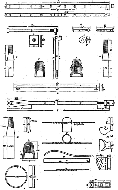
| Fig. 1. — Details of New York-Chicago Telephone Line Construction. |
But it was early surmised that if regular telephonic communication were provided between distant cities, and subscribers offered facilities for communication which would involve no more trouble than that experienced "in the" ringing up of a local correspondent, a business could be built up which could be made profitable. This idea, which had lain dormant for some time, was seriously taken up in 1885, when the American Telegraph and Telephone Company, familiarly known as the Long Distance Company, was organized, and its active management placed in the hands of Mr. E. J. Hall. The first line was built between New York and Philadelphia, and its success was so immediate and spontaneous, that if any doubts had previously existed as to the commercial value of long-distance telephone lines, they were dispelled; and the confidence of the officers of the company in the correctness of their estimates was so strengthened that additional lines between Boston and New York were immediately constructed.
 |
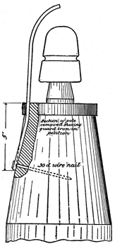
| Fig. 2. — Guard Iron on Top of Pole. |
II.
Up to the time at which the New York and Chicago line had been contemplated, the longest sustained successful telephone transmission had been about 500 miles, and it was, therefore, a matter for no small consideration, and one, the importance of which, the company well recognized, that the operation of a line almost twice this distance should be successful at the very start. The previous experience of the company stood it in good stead, but the rules which had been laid down for the calculation of the size of wire required for the transmission of speech had been found to be at such variance with the actual practice of the company, that its engineers were necessarily obliged to observe the greatest caution in their recommendations. The most commonly accepted rule for telephonic transmission is that laid down some few years since by Mr. Wm. H. Preece, chief engineer and electrician of the British Postal Telegraphs, which is as follows:
When K R = 15,000, speech become impossible
When K R = 12,500, speech become possible
When K R = 10,000, speech becomes good
When K R = 7,500, speech becomes very good
When K R = 5,000, speech becomes excellent
When K R = 2,500, or under, speech becomes perfect
This rule, it must be pointed out, is entirely empirical, and as such, as frequently turns out to be the case, is only safely applicable to circuits whose length is within the limits of those by which the rule was formulated. As proof of this we may remark here that the telephone line between Paris and London was built according to this rule, and the K R constant of 7,500 was adopted. When the line was finished it was found that transmission over it was very much better than the formula indicated, which went to prove that the rule apparently did not apply to that particular line. But long before the completion of the Paris-London line, it was well known to the engineers of the Long Distance Company, that this rule was not generally applicable, for the reason that the circuits at their command showed that transmission was possible over lines having a very much higher K R constant. Thus among the experiments tried by them was the coupling up of lines aggregating in length from 650 to 1,100 miles. The results obtained are shown in the following table:
650 miles, excellent transmission with K R = 31,000
750 miles, good transmission with K R = 45,000
885 miles, poor transmission with K R = 62,000
1,100 miles, no transmission with K R = 91,000
These experiments were made with a "solid-back" transmitter, and three cells of Fuller battery, the usual equipment of the long-distance telephone set.
According to the formula enunciated by Mr. Preece, it would require a wire weighing nearly 2,200 pounds to the mile in order to communicate with Chicago, and it was not to be wondered at, therefore, that the engineers of the Long Distance Company hesitated in applying this rule. The results of their own experience, however, was such as to give them confidence in the selection of a greatly reduced size of wire, and after due consideration it was determined to select a No. 8 B. W. G. wire, having a diameter of .165 inch, and weighting 435 pounds to the mile. This wire has a resistance of 2.06 ohms per mile, and a capacity of .0158 microfarads per mile, with wires strung 35 feet above the ground. 1,000 miles, practically representing the distance between Chicago and New York, has a K R constant of 32,000. Yet notwithstanding this enormous excess over the limiting figure laid down by Mr. Preece, it was adopted and the line built. The results obtained are now well known, but even before the building of the line was begun the engineers of the company were firm in the conviction that it would prove to have such excellent speech transmitting qualities, that it would give a sufficient margin to make it possible to add on other lines at the end and possibly secure communication to cities beyond Chicago, such as Minneapolis, St. Paul and St. Louis; while, on the other had, it would leave large margin for the attachment of local lines within a radius of 100 miles from Chicago.
As another proof of the inadequacy of the transmission formula, as laid down, it is only necessary to consider the following K R constants for lines which are now, and have been for some time, in daily operation, as follows:
Boston and Washington, K R = 26,250 Boston and New York, K R = 12,100 New York and Philadelphia K R = 2,000
From the above it is evident that while the lower figures given by Mr. Preece agree thoroughly well with the results obtained on the long-distance lines, the higher figures are greatly at variance with it, the circuit between Boston and Washington, for instance, exceeding Mr. Preece's figure for speech "impossible" by nearly 75 per cent.
As some question might be raised as to the manner in which the K R constant is here calculated, it might be well to point out the fact that Mr. Preece multiplies the total resistance of the circuit by the capacity of one of its wires measured against its mate, and estimates that the capacity of one wire measured against its mate is one-half of what it would be if measured to ground. In the calculations made by the Long-Distance engineers, they have taken the resistance of one of the wires of a metallic circuit, measured in ohms, and multiplied it by its electrostatic capacity measured in microfarads, to ground. The difference evidently is one of method only, the result being the same. It might be well to point out here that one wire measured against it mate, as done in the calculations of Mr. Preece, is never found to be exactly one-half of the capacity when measured to ground, being usually found to be from 60 to 65 percent of that quantity.
 |
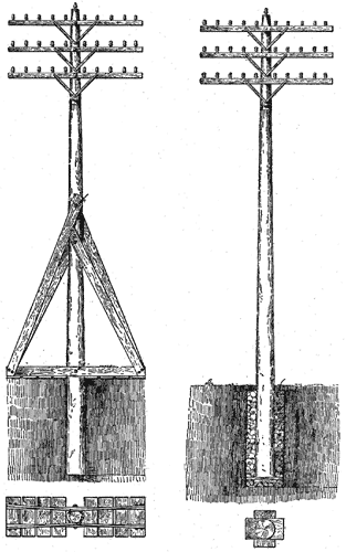
| Figs. 3 and 4. — Method of Pole Setting in Soft Ground. |
III.
The building of the line having been determined upon, the questions of the details of construction to be adopted were given most exhaustive study. In this respect the experience of the company in its past work has also stood it in good stead, with the result that it is fair to assume, that the construction adopted will afford a line of the most permanent character.
The line is built of standard poles 35 feet long, of the best quality of live, green cedar wood, peeled, and the knots trimmed close. This length of pole permits it to extend not less than 26 feet above the surface of the ground.
The cross-arms employed are of thoroughly seasoned, straight grained Norway pine, 10 feet long, 3 1/4 inches thick, and 4 1/4 inches deep, as illustrated at A in the diagram Fig. 1, which allows the auxiliary details of construction complete. These cross-arms are given two thorough coats of metallic paint, and are braced with two galvanized iron braces, shown at L, Fig. 1, which are attached to the cross-arms by means of galvanized iron carriage bolts, shown at C. These cross-arms are fastened to the pole not in the usual way, by means of fetter drive screws, but by a galvanized iron bolt shown at B, the pole being bored for the purpose, and the bolt passing entirely through. Washers under the head and nut prevent abrasion of the cross-arms and the pole.
The insulator pins are made of clear split locust, 1 1/4 inches in diameter, and have the general outline shown at G. The transposition pin is shown at K. The pins are nailed to the cross-arms with heavy galvanized iron wire nails driven in straight from the middle of the side of the cross-arm.
The type of insulator employed is the regular standard white glass American Telegraph and Telephone Company's insulators, shown at H. For the guard wire the 20-ounce Western Union double petticoat insulator, without petticoat, is used as shown at O, Fig. 1. The transposition insulator is of the Hibbard pattern, of white glass, and is shown at J.
On the corner poles guard irons are employed as shown in Fig. 2, and at W Fig. 1, passing under the ring at the top of the pole. Every tenth pole is furnished with a lightning rod made of No. 6 galvanized iron wire. These rods are fastened to the pole every two feet by iron staples extending from the top to the bottom, and at the latter end they are given two hand turns.
In ordinary good ground the poles are set at distances of 130 feet to a depth of 6 feet, and on curves to a depth of 6 1/2 feet. Where the earth is soft so as to prevent proper tamping the construction illustrated in Figs. 3 and 4 have been adopted.
The method of tieing the wires is shown at T Fig. 1. Hence it will be noticed that one side of the tie wire passes around the line wire and makes five complete turns. The joints in the copper line are made with McIntire sleeves, each sleeve being given three complete twists as shown at V, Fig. 1.
 |
| Fig. 5. — Method of Transposing Wires, New York-Chicago Telephone Line. |
IV.
In laying out a telephone line great car must, of course, be taken to avoid cross-talk and other disturbing influences, which militate so much against clear enunciation, and makes wires noisy. For this purpose it is necessary to transpose the wires at proper intervals, and to accomplish this transposition insulators are employed. Fig. 5 shows the method of carrying out the transposition. It will be noted that the line coming from the left is dead-ended on the upper insulator, and continued by means of a cross-over connector to the neighboring line, its mate. This line is also dead-ended on the other upper insulator. In the same way the other two sides are joined so that the position of the conductor on each side of the cross-arm is reversed. The present line carries two cross-arms which will eventually carry 10 wires each, and the transpositions employed on the upper and lower cross-arms are clearly shown in Fig. 6.
 |
| Fig. 6. — Scheme of Circuit Transpositions, New York-Chicago Telephone Line. |
The route over which the line has been constructed is illustrated in the map, Fig. 7. The line, it will be noted, passes through, or is connected by short branches and loops with, the most important cities between New York and Chicago.
 |
| Fig. 7. — Detail Map of New York-Chicago Long-Distance Telephone Line |
We have already referred to the credit which must be accorded to the enterprise and management which has made the New York-Chicago line a possibility, but we cannot close this description without a brief mention of those who have had immediate charge of the work and have brought it to a successful completion. Mr. E. P. Meany, assistant general manager of the Long Distance Company, has had charge of the construction work of the entire line, and F. A. Pickernell, engineer of the company, has had general charge of the electrical and mechanical working out of the system; while Mr. A. S. Hibbard, the general superintendent, has had charge of its operation and maintenance. The company is to be congratulated on the possession of the services of men so thoroughly competent, and whose work will no doubt prove of permanent value to the profession at large.
