[Trade Journal]
Publication: Electrical World
New York, NY, United States
vol. 10, no. 11, p. 144, col. 2-3
The Brown Duplex Pin and Insulator
Heretofore many devices have been resorted to for hanging wire to the under side of cross-arms in order to increase the carrying capacity of pole lines. The majority of these insulators, such as rubber hooks, porcelain knobs, etc., are expensive, and they have the disadvantage of supporting the line wires too close to the arms, with the result that the wires hang so close together that whenever there is a heavy wind the wires are in continual trouble and crosses are of frequent occurrence.
In addition to this, much difficulty is experienced in putting up these insulators, particularly in cases where the line is already constructed, it being necessary to bore a hole in the under side of the cross-arm, into which is screwed the hook or other device. Another common objection to this class of insulator is due to the near proximity of the wire to the arm; this attracts insects, who build their nests in and around the insulators, causing an ever increasing defect in the insulation of the line.
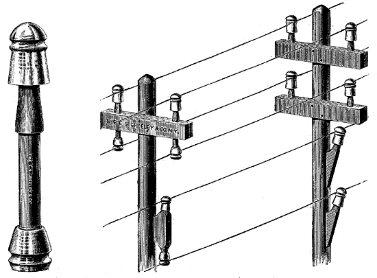
In order to avoid all these difficulties, Mr. R. G. Brown, electrician of the Standard Multiplex Telegraph Company, designed the duplex pin and bracket illustrated in the accompanying engravings. The oak pin shown in Fig. 1 is made longer than usual, so as to project some inches through the cross-arm. A thread is cut on both ends, so that an ordinary pony or other glass insulator can be screwed on the top and a new glass insulator of Mr. Brown's design screwed to the lower end, as is clearly shown.
 |
| Figs. 1 and 2. - Brown Duplex Pin and Insulator. |
The lower insulator has an opening which extends centrally through it from top to bottom. The wall of this opening is screw-threaded throughout its length.
It is evident that when this insulator is screwed upon the downwardly-projecting pin, which is to sustain it upon the cross-arm, any moisture, as from rain, which may fall upon the rounded or convex top will readily flow off, and in case any moisture should find entrance into the opening about the pin, its tendency will be to pass downward and flow out or escape through the bottom of the opening.
Fig. 2 is an illustration of a six-wire line such as is often seen in the country. One pole shows the present system of cross-arms, pins and brackets, and the remaining pole shows the new system.
It will be noticed that although the two poles shown are installed, one with the new and one with the old system, the wires on both poles are held at exactly the same distance apart, and further, that the under insulator and its wire are some inches away from the cross-arm. Consequently the objections pointed out as existing in the present system, whereby the wires are liable to become crossed by the fact of their close proximity to each other, and the poor insulation caused by insects, nests, etc., are impossible under the new plan. The system is specially adapted to the building of telephone lines, both for pole and housetop work. As there are but one-half the number of cross-arms, pins, and bolts required, the cost in construction is less and the line presents a lighter, neater and less objectionable appearance in the eyes of the public.
Taking for example the two poles shown in the drawing it will be seen that there is an actual saving of 1 cross-arm, 2 pins, 2 bolts, 1 bracket and 2 spikes; this on a single pole carrying six wires. But presuming the line to be an eight-wire line, say five miles in length, on the basis of 40 poles to the mile, the results would be as follows:
Present system ...................... New system
Poles....................................... 200 200
Four-pin arms........................... 400 200
Bolts......................................... 800 400
Washers.................................... 800 400
Pins........................................... 1,600 800
Insulators................................... 1,600 1,600
To the actual saving in material must be added the saving in transportation and labor on the same, which is an important item to be considered. The system offers a number of advantages in the construction of house-top lines. The "fixtures" can be made of a less number of parallel cross-pieces or cross-arms, which will permit of less expensive, lighter and more desirable fixtures.
It is evident that the carrying capacity of pole lines built on the present plan can be greatly increased and at a very low cost by means of the Brown duplex pin system, it being necessary to simply pull out the old pins and insert the new. The old insulator can, of course, be utilized on the top end of the new pins. The duplex brackets have been designed especially for cases where it is desired to build a two-wire line through woods, over house tops, etc., and both the pins and brackets for cutting-in purposes, test stations, etc.
The E. S. Greeley & Co., of this city, are now introducing this system.
