[Trade Journal]
Publication: The Electrical Engineer - London
London, England
vol. 12, no. 16, p. 376-377, col. 1-2
COOK, SMYTHE, AND PAYNE'S PATENT FIRE PROOF SYSTEM OF CONDUCTORS.
These conductors were designed with the object of providing a mechanical system of conductors that would stand the same wear and tear that gas and water pipes are subject to when erected in the interiors of buildings. No vegetable substances are used in their construction and no inflammable materials. The conductors may be com posed of tubes, strips, or wires placed inside tubes or tubular casings, and kept apart by means of insulators of suitable form fixed at intervals along the conducting tubes, wires, etc.
When arranged on the concentric principle a tubular strip is usually employed, to which insulating rings are fixed both inside and out. The tubular strip is not brazed nor soldered along the edges, but left open, and the rings are made to fit tightly inside and outside, so that they are held firmly in position by the mutual inward and outward pressure against the tubular strip. The inner insulators are provided with holes through which a rod or wire is afterwards drawn, the wire forming the lead and the strip the return for the current; these are then placed inside an outer tube that serves as a protection. The conductors can thus be made up in lengths in the workshop, and sent out ready for erection. Conductors arranged on this principle are very rigid, and are useful for vertical mains that may be used in large buildings to supply current to the different floors.
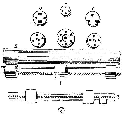 |
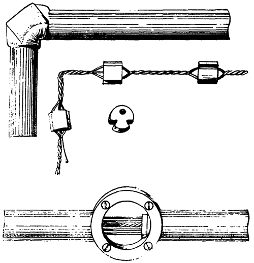
| Figs. 1, 2, and 3. |
Joints are made in a variety of ways by means of wires or strips soldered to the tubes. A useful plan, where the current is to be subdivided on a distribution board, is to solder the end of the tubular strip into a brass or copper ring with holes round the periphery fitted with screws under which connecting wires may be fixed for jointing to the fuses on the board.
Another method of insulating the tubes consists in the employment of small porcelain studs fitted into holes at intervals along the inner tubes. It is impossible to shift these studs out of position without breaking them.
When ordinary wires or flat strips are used, the insulators are made with one or more suitable holes through them to receive the former. If ordinary wires of circular section are employed, two are used; if a wire of rectangular section or a ribbon is used, one is sufficient. The insulators are first threaded on to the wires or strips at intervals, after which the latter are twisted, which fixes the insulators in position. Other wires can then be drawn through other holes to form leads or returns for other circuits. The twisted wires may be passed along grooves in the sides of the insulators as shown at a, b, and c. This avoids the necessity of threading, and enables a machine to be employed. The wires thus insulated can be made up in coils like covered wires, and sent out ready for drawing into the tubes.
For making L and T bends, joints, etc., a very large number of junction-boxes, jointing-pieces, and insulators have been devised to meet all requirements. Metal boxes made of two or more parts-castings or stampingsand all interchangeable, may be used; these can be fitted on round the ends of the tubes, one half being usually fitted to the wall or ceiling, the other half acting as a cover that can be put on after the tubes have been placed in position, and the joints (if any) made.
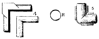 |
| Figs. 4 and 5. |
L and T junctions are also used. Fig. 4 shows an L-junction for going round corners. Fig. 5 shows another made with press tools, and fixed together by means of rings, R, or clips slipped along the projecting edges or feathers that are turned up to receive them. This is shown open in Fig. 7.
If a ring occurs exactly at a joint, as at A, Fig. 6, no. further insulation is required; if not, as at B, an insulator with grooves in it may be inserted, if necessary, at C.
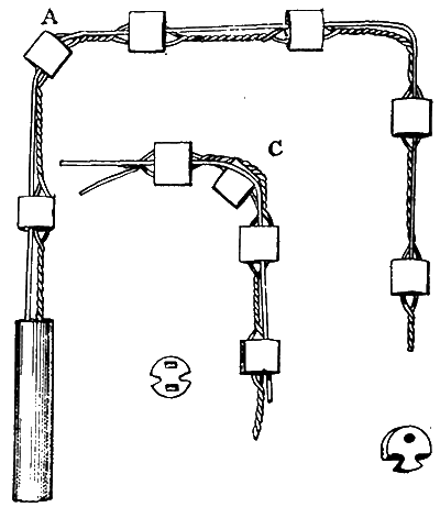 |
| Fig. 6. |
 |
| Fig. 7. |
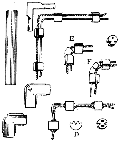
For very special work, where the exact position of the bend is known small rings may be threaded on to the twisted or to the other wire or wires, as at E and F.
If it is desired to break the metallic continuity of the outer tube, a porcelain junction may be employed which has grooves inside that can be fitted round the wires; these are made in two parts with projections fitting inside the ends of the tubes, as shown in Fig. 8.
 |
| Figs. 8 and 9. |
Fig. 9 shows another insulating junction, which acts also as a support; these are most convenient where ceiling roses are used, or other similar fittings, in combination with the tubes.
Special attention has been given to the construction of rows of lights when fixed to tubes whether fixed or port able, such as those used for showrooms and shop windows, and for the floats, battens, or lengths employed for stage lighting. A long tube with 50 lights arranged in this manner has recently been erected in the new Victoria Concert Hall at Langham-place for lighting the orchestra.
The fireproof nature of the arrangement is one of the chief advantages claimed for the system. The conductors can also be erected in hot places-boiler-houses, engine rooms, factories, etc.--without any risk of the insulation being injured by the heat, as is the case with rubber covered wires.
With regard to the permanent character of the insulation. the inventors wish to point out that the conditions of working where bare conductors are used for interior wiring are usually the reverse of those met with in connection with underground conduits. The temperature of a conduit is often lower than that of the air above, and when moist air finds its way into a cold conduit there may be some condensation; the interior of a building, however, is usually warmer that it is outside, and this condensation is not found to take place.
There are usually many places in an installation where the lamps are fixed close to or on the tubes, and when lighted acted as small stoves, keeping the tube warm and promoting circulation of the air.
When the conductors are erected in boiler-houses, or near furnaces or ovens, or laid in recesses in walls or floors near hot-water pipes, the insulation, if anything, is improved. In places exposed to the heat of the sun, and in hot countries generally, these conductors can be employed where shellac, paraffin, wax, and rubber insulation would be unsuitable.
