[Trade Journal]
Publication: Electrical World
New York, NY, United States
vol. XXIX, no. 1, p. 33, col. 1-2
High-Potential Insulators.
The increasing use of high-potential currents for long-distance transmission of power has naturally necessitated great improvements in the insulation on the lines, and among the concerns and individuals most successful in meeting this condition is Mr. Fred M. Locke, Victor, N. Y.
At various times in the past we have prepared for the information of the trade descriptions and illustrations of different types of insulators made by Mr. Locke, and now we have other new designs to present.
| |||
| Fig. 1. - High-Potential Insulator. |
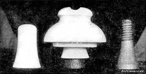
In the accompanying illustrations Fig. 1 represents one of Mr. Locke's new insulators, designed for extremely high potential line work. Fig. 2 shows a larger size of the same device, and Fig. 3 illustrates a cross-sectional view, as will be seen from the latter illustration. This insulator is a combination of glass and porcelain, the inside part being glass and the outside porcelain. Another type is made with both parts of porcelain.
| |||
| Fig. 2. - Large Size of High-Potential Insulator. |
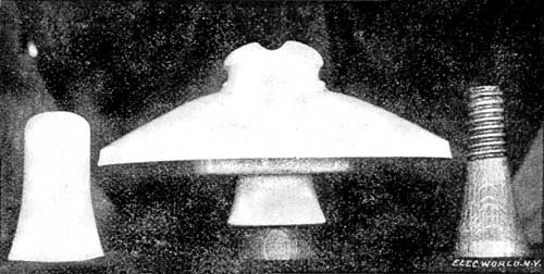
By constructing these insulators with the inner member of glass it is claimed that it is almost impossible to puncture or break down the insulation, glass offering the highest resistance against puncture and porcelain extremely high surface resistance. It is also claimed that by making insulators of two porcelain parts each part may be made thinner and more easily, thus allowing better vitrification throughout.
 |
| Fig. 3. Cross-Section of Insulator. |
The two parts are screwed or fused together and are very strong mechanically as well as electrically. In several tests made on these insulators, set on steel pins, they stood 70,000 volts for four hours without heating, breaking down or arcing.
The insulator is designed to carry currents from 20,000 to 50,000 volts without loss.
| |||
| Fig. 4. - Other Designs of Insulators. |
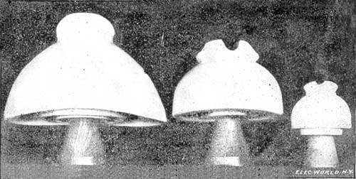
The insulators shown in Fig. 4 are designed for currents up to 25,000 volts. The one at the left is the design used on the Niagara Falls and Buffalo transmission lines; the others are used throughout the country on circuits carrying 10,000 to 15,000 volts, all of which are said to be giving perfect satisfaction.
All of these insulators are mounted on Mr. Locke's steel pin with locust tips boiled in paraffin.
