[Trade Journal]
Publication: Electrical World
New York, NY, United States
vol. XXXI, no. 4, p. 122-123, col. 1-2
The Testing of Insulators for High Tension Service
BY J. R. HASKIN
|
Of the many things to which careful attention must be paid in the construction of a long-distance line for the transmission of electricity at high pressure, one of the most important, if not really the most important, is the proper testing of the insulating devices. Unless each insulator is thoroughly capable of withstanding the pressure and strain to which it is to be subjected when in service, there will necessarily be one or more unknown weak spots, which by their breaking down will necessitate the discontinuance of service until, after more or less trouble and delay, the particular location of the trouble is found. Too much attention therefore cannot be paid to the thorough testing of the insulators before installing them.
When the Niagara-Buffalo transmission line was about to be constructed, the question of insulation received very careful attention from the electrical superintendent of the company, Mr. Paul M. Lincoln, who after careful deliberation designed two transformers, each capable of producing a pressure of 20,000 volts. The primaries of these transformers, which are connected to a 110-volt circuit of 25 cycles, consist of a number of turns of No. 10 cotton covered wire, while the secondaries are made up of ten coils of No. 30 silk-covered wire, each having a ratio of 20 to 1 to the primaries, thereby giving a pressure of 20,000 volts in each transformer when its secondary coils are connected up in series. One of these transformers is equipped with a small plug switchboard, to which is connected a lead from each of the secondary coils, by means of which the voltage used for testing may be varied from 2000 to 20,000 volts.
| |||
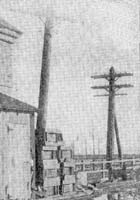
| Crossarm, Pin, Insulator and Cable, Niagara Line |
Shortly after the transformers had been completed, a number of barrels of insulators arrived, and it became necessary to put them in use at once. The transformers were mounted in wooden boxes, which were afterward enclosed in a tin casing in order to make them oil tight, and in order to thoroughly insulate them they were submerged in a thin oil. Except for breakdowns in one or two of the secondary coils, due to faults in the winding by which two sections of wire having a considerable difference in potential came in contact with each other, no trouble was experienced with the insulation, the transformers being protected from overload and the consequent possible burning out by fuses placed in the primary circuits. For convenience, it might be added, that small double pole switches and pilot lamps were furnished to each transformer in the primary circuits, these, together with the main switches, checking each other and acting as safeguards to the operator.
The manner of testing the insulators may be briefly described as follows: The insulators were placed in an inverted position in a square iron pan capable of holding a dozen or more; the pin holes were filled up half full with salt water and the insulators were also submerged in the same to within about an inch of the edge of the outer petticoat. One lead from the transformers was attached to the pan and the other to a short bar of zinc or copper, this being placed in the pin hole of each insulator in turn.
During the early tests a pressure of 20,000 volts was first applied, and if the insulator stood this test the pressure was gradually increased to 40,000 volts, but after the first few had been tested it became customary to apply the entire 40,000 volts pressure at once. If the insulator is satisfactory, nothing will be noticed except a subdued humming sound caused partly by the transformer and partly by the discharges due to a condenser action on the surface of the insulator, with ofttimes a snapping blue, static spark jumping from the edges of the pin hole to the outer petticoat edge of the insulator, this latter phenomenon generally appearing when the surface of the insulator is at all moist or has upon its surface a few drops of the salt water accidentally spilled upon it. But if there is a slight flaw in the make-up of the insulator a yellowish spark will immediately manifest itself, and if the breakdown is at all serious this spark may be seen coming through the top surface of the inverted translator, below the level of the brine. And right here is where the advantage of having salt water becomes evident, as will be shown later on.
When the first lot of insulators arrived there was urgent need of haste on account of contracts in Buffalo, which it was necessary to fill at a certain date. So when on testing these insulators it was found that a very large proportion of them failed to pass the above mentioned test, in spite of the fact that they had been tested by the makers before shipment, it was urged by the contractors that the test was too severe. Experiment showed that when fresh water was used instead of brine, a much larger proportion of the insulators passed the test and were apparently sound and well made. It is rather difficult to say why this should be, but the fact remained nevertheless. A few days later, however, another lot of insulators having arrived from another manufacturer, it was found that a very fair proportion of them stood the test with brine satisfactorily, and it was then decided that the test was none too severe. Owing, however, to the necessity for haste in the equipment of the transmission line, the first lot was tested with 20,000 volts only, with the proviso that these should be replaced as rapidly as possible with other and better insulators. It is a curious fact that out of 1000 of these insulators which were tested again after having been in service but a month or two, all but one broke down.
| |||
| A. Ink Spots on Good Porcelain B. Ink Spots on Bad Porcelain |
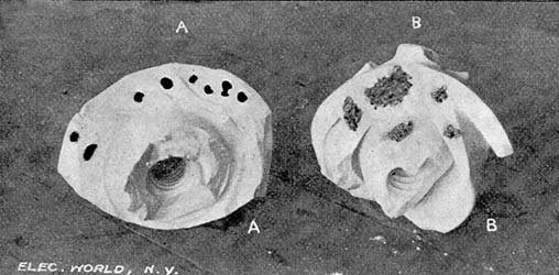
Regarding the test said to have been made on these insulators by the manufacturers, it was learned on inquiry that they had been merely set in a row while still warm from the kiln in which they had been baked, and touched on the outside and inside with the terminals of a transformer giving 40,000 volts pressure. The reason for their poor insulating properties was easily made apparent by breaking up one of the insulators and examining the porcelain, which was found by the application of red ink to an unglazed surface to be very porous. In nearly every case also, flaws caused by imperfect kneading of the clay were found, poor lots of insulators being often filled with these imperfections, while only one or two flaws would be found in the imperfect ones from a lot which gave a high percentage of satisfactory insulators.
Too much importance cannot be given to this matter, as it is above all the prime requisite of a porcelain insulator. A perfect piece of porcelain three-sixteenths of an inch in thickness, is for all practical purposes non-puncturable. For example, a number of small insulators, measuring but 2 or 3 inches in diameter, were brought to Mr. Lincoln's office by a representative of a well-known firm, with a request that they should be tested to their full capacity. This capacity proved to be about 30,000 to 32,000 volts, it being impossible to raise the pressure any higher, owing to the fact that a spark would jump over the surface of the insulator when using the rather crude form of apparatus which was designed for the testing of much larger insulators. These insulators were less than three-sixteenths of an inch in thickness in some parts, but on breaking them open they were found to be of good porcelain and without a flaw.
The necessary size of the insulator to be used appears to vary somewhat according to the climatic conditions of the locality in which they are to be installed. The writer has been informed that in certain sections in the West where the climate is very dry and the air thin, power has been and is now being transmitted at a pressure of 50,000 and 60,000 volts on wires insulated only by the ordinary glass insulator in common use by the telegraph and telephone companies. In such a locality as Niagara Falls this would be impossible, as the moisture and dust collecting on the surface of the insulator would be sufficient to allow the current to leak across even when but 10,000 or 15,000 volts were being used. Therefore, a large insulator made of the first quality of porcelain, well baked and vitrified, is the only one that will stand the pressure and wear of a high tension transmission line in such a locality.
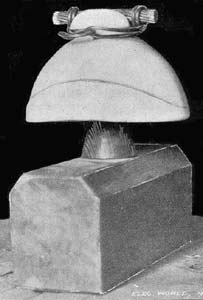
There are a number of types which might be used to advantage, two distinct ones being in use on the Buffalo transmission line, one being round and have a triple petticoat, the other being what is known now as the Niagara helmet type insulator, the name of which very fully explains its shape. This latter has also a triple petticoat, and is besides furnished with a small gutter on the two sides, arranged in such a way as to lead off dripping water to the ends where it may fall clear of the cross arm.
So important is the quality of the porcelain in the making of a good insulator that I am tempted to give the result of several other experiments which we made on this subject during the period occupied in turning out insulators for the transmission line. One lot of samples sent for test by a large manufacturing concern was made up of several parts or layers, each layer having been formed, baked and glazed separately and the various parts set together and again baked, the glaze uniting them into one solid insulator. While the porcelain of these insulators was found on examination to be full of flaws it was claimed that having been made up in separate parts, these flaws could not go completely through the body of the insulator, and furthermore, the various layers of glaze acted in favor of the insulating qualities; but after soaking several of these samples in a solution of salt water for several days, it was found that everyone of them broke down at a considerably less pressure than 40,000 volts. On examination it was discovered that the porcelain was so porous that it was - one might say - water logged.
Many other sample lots were found to have this defect also, it being often readily discernible upon an application of red ink to an unglazed surface, the red ink showing clearly all cracks and porous parts of the porcelain. In every case it was found that a good quality of porcelain insured a high percentage of satisfactory insulators and vice versa.
In conclusion, no better proof of the satisfactory nature of the test above described can be given than the working of the overhead system of the Buffalo transmission line since the commencement of its operation. Except for a few cases of breakdown among the insulators that had been installed temporarily, it has been necessary to remove only two or three insulators out of the whole set of more than 12,000.
