[Trade Journal]
Publication: Electrical World
New York, NY, United States
vol. 48, no. 3, p. 137-139, col. 1-2
Steel Cable and Tower Transmission Line in Syracuse.
Mention has been made in our columns from time to time of the 60,000-volt transmission line from Niagara Falls to Syracuse, and detailed information was given in our issue for April 14, 1906, concerning the steel towers used in the neighborhood of Niagara Falls and from Niagara Falls to Rochester, and the wooden frames employed from Rochester to Syracuse. We are able to give below a description of the transmission line in Syracuse, where both the poles and the cables are built of steel.
From the western city line of Syracuse, for a distance of two miles, the transmission line is carried on especially designed steel towers over three railroads and several factories and buildings, and terminates at a substation of the Syracuse Rapid Transit Company on the bank of the Erie Canal at Tracy Street. Along this portion of the route there are forty towers, ranging in height from 45 ft. to 63 ft., measured from the ground to the top of the bottom insulator. The total length of the towers in each case is from 10 ft. to 11 ft. longer than this when the sections entering the ground and extending above the bottom cross-arm are included.
An unusual feature of the equipment resides in the use of steel cable for the conductors. Each leg of the three-phase circuit consists of a sever-strand, 7/16-in., plow-steel cable. Each cable is strung in one length from the terminal at the sub-station to the terminal at the city line. Steel was used in these cables in place of copper or aluminum, primarily for greater strength. The average span is approximately 240 ft., the longest single span being 407 ft.
 |
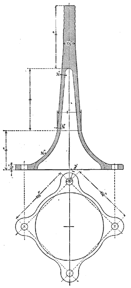
| Fig. 1. — Details of Insulator Pin. |
The insulators are of the 60,000-volt, triple petticoat, porcelain type, supplied by R. Thomas & Sons Company, of East Liverpool, Ohio. The insulators are carried on the cross-arms by means of special malleable-iron pins. The form of the pin is shown in Fig. 1. It will be noticed that the pin has a flat base designed to set squarely upon the cross-arm, to which it is bolted by means of four 5/8-in. bolts. This method of attaching the pins to the towers was adopted for greater convenience in installing. The parts of the insulators are cemented together and the insulators are connected by the pins. Each cable is tied to the insulators with annealed tie wire so arranged as to break at a maximum pull of 1,000 lbs. in order to avoid breaking the insulators or cross-arms should unusual strains be put upon the cables. At the double cross-arm and dead end-towers the cables are clamped to equalizing saddles cemented to the top of the insulators. The saddles are arranged to facilitate removing a broken or defective insulator.
In designing the line the assumed wind load was taken as 1-1/4 lbs. per lineal foot of cable, based on 1/4 in. of sleet and a wind pressure of 30 lbs. per ft. on a flat surface, or 15 lbs. on a round surface. The dead-end towers were designed to provide also for endwise strains under maximum wind and sleet loads; calculating these strains, a sag not exceeding one-twentieth of the span was allowed. The minimum sag allowed was 1 ft. in 40 ft. The heights of towers was arranged to provide ample clearance over buildings and wires. The towers at the angles were designed to provide for side strains due to the tension in the cables based on the sags stated, and also for the pressure of the wind on the cable and on the tower. Enough insulators were provided at the angle towers so that the cable does not make any angle of over 8-1/2 degs. on any one insulator. Where possible the cable was slacked off on spans adjacent to angles of over 2 degrees. The towers at angles and dead-ends are stiff structures designed to provide for the greatest assumed strains. The wind pressure on the tower itself was assumed at 60 lbs. per panel on each half of tower.
 |
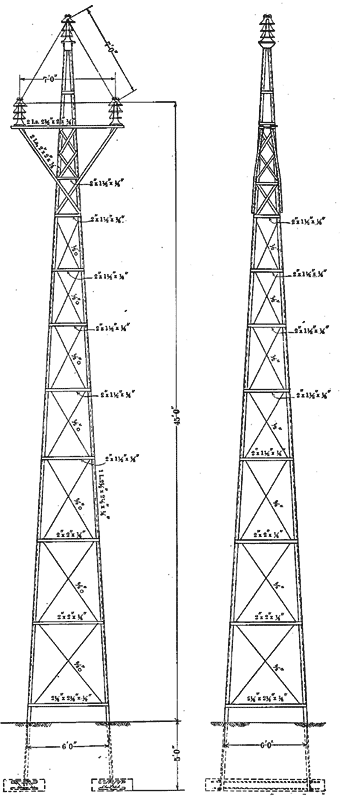
| Fig. 2. — Details of 45-Ft Angle Tower. |
The design of the towers in general is as indicated in the drawing of a 45-ft. tower shown in Fig. 2. In towers of greater height the section of the upright members in the lower panels was increased. The cross-arms of all towers were designed to resist torsional strains due to the pull of the cable on the top of the insulators. The maximum pull allowable on a single cross-arm tower was 1,000 lbs. for each cable, the ties, as stated, being designed to break at this tension. The cross-arms of towers at dead-ends carry three insulators for each cable, and are designed to resist the maximum calculated pull due to the assumed conditions of load and sag. Bolted joints in the main members of towers were designed on the basis of 10,000 lbs. shearing per sq. in. and 20,000 lbs. bearing per sq. in.
The following are the chief features of the towers: Towers 57 ft. high and over are supported on concrete piers. Each leg of the tower is anchored by two 1-in. bolts running to the footings. The footing under each pier is 5 ft. x 3 ft. x 10 in. thick, reinforced at the top to resist uplift. For the lighter towers under 57 ft. high, the concrete piers were omitted and the legs of the tower were spliced to angle-irons which extend down into the ground. Each of these angle footings was enclosed in a piece of stove pipe which was filled with cement grouting to prevent corrosion.
The towers were riveted in complete form so far as practicable at the shop, the actual field connections being bolted at the point of location before erection. The towers were raised and set, completely assembled, by the use of a tower wagon. The erecting wagon had a boom 40 ft. long, which was first raised by means of black and fall and a team of horses. The boom was then guyed three ways and used as a gin pole for erecting the tower. On similar work the contractor with this apparatus, one team, and a gang of eight men has raised as many as twenty towers in one day.
The towers were given one shop coat of red lead and oil and one coat in the field of graphite paint. They were erected by the Archbold-Brady Company, of Syracuse, which acted as engineer and contractor, and furnished the design for the towers and the insulator pins.
