[Trade Journal]
Publication: The Journal of Electricity, Power and Gas
San Francisco, CA, United States
vol. 11, no. 11, p. 263-264, col. 1-2
THE DEVELOPMENT OF THE LOCKE INSULATOR.
BY FRED M. LOCKE.
In a recent letter to the writer, the editor of The Journal expressed the opinion that it would be pertinent at this time to contribute an article upon the inception and development of the type of insulator used in the system of the Standard Electric Company of California, and in that of the Bay Counties Power Company, and it is in accordance with the wish submitted by him that the following is written:
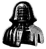 |
| Figure 1 — No. 15 Glass Insulator. |
It was in the winter of 1883-4, while employed, jointly, by the New York Central and Hudson River Railroad and the Pennsylvania Railroad Companies, at Canandaigua, New York, that my attention was called to the need of better insulation on our telegraph lines by a rather peculiar circumstance. The principal part of my work was between Canandaigua and Harrisburg, Pa., over quite a long line, and a good share of the time the insulators were wet or damp from rain or fog, which allowed a small leakage over each insulator, and being a grounded circuit, the operator at either end, upon opening his key to answer a call, would force the entire current over the wet insulators and to ground. Thus was formed a new circuit, over which Harrisburg office could continue to call and I was unable to answer, the opening of my key affecting his relay only under very fine adjustment. The result was that my office was very frequently reported for not answering calls and to free myself from blame I quietly began an investigation.
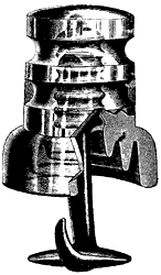 |
| Figure 2 - Insulator for Under Side of Crossarm. |
I recall that when mopping the office floor, having wet shoes, and accidently [sic] accidentally touching the key when operating, part of the current would ground through me. With this in view, and interposing between my finger and the key, a wetted glass plate, I was able to crudely measure the distance over which a perceptible leakage took place; applying my tongue in place of finger I could make more delicate measurement by tasting ($30.00 per month allowed me no finer instruments) and I determined that a length of about 8 inches of wet glass surface was nearly perfect insulation for 2500 volts. In possession of this data, I designed what is now known as the No. 15, 4-1/2-inch glass insulator, triple petticoat, an illustration of which is herewith presented. This is the first recorded designed "triple petticoat" insulator. Shortly afterward I brought out another design, which is also illustrated, and which was fitted to be received into the under side of the crossarm and fastened with wood pins or dowels, thus affording protection for the insulator.
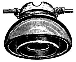 |
| Figure 3 - Triple Petticoat Porcelain Insulator, One Piece. |
Crude induction coils were at that time made, and glass plate machines were used by me to raise the potentials in a series of experiments then carried on to determine the best material for efficient insulators. It was soon ascertained that of all materials at hand, glass and porcelain were the two at the front. Glass showed great resistance against puncture; porcelain greater surface resistance. Porcelain, if capable of withstanding the required potential, does not deteriorate with time and use, and lose its efficiency as a dielectric, as does glass. The next insulator designed was a triple petticoat porcelain, illustrated herewith as figure 3.
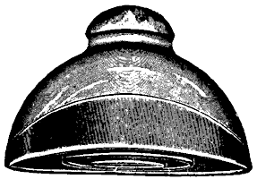 |
| Figure 4 - Eave-Trough Type of Plain Insulator. |
Exhaustive experiments were then carried on with a view of ascertaining the best means of carrying water off from the outer top surface of insulators wet from rainfall, etc. As a result the eave-trough type was developed. Three of these designs are shown in figures 4, 8 and 9. I next decided, from my searches, as to what constituted efficient porcelain for this work, and being unable to manufacture it myself, I was forced to look to porcelain manufacturers for this product. I continued for some time to have my insulators made for me in this manner, but soon found that no reliance could be placed upon the uniformity of their ware as commonly manufactured, and that it would be necessary, for successful use of porcelain for very high voltages, to manufacture this myself. Experiments with the aid of a cook stove were first carried on; finally, with a small kiln, from the use of which I became convinced that a porcelain could be made suited to withstand almost any voltage.
 |
| Figure 5 - Showing Shell Construction. |
 |
| Figure 6 - Insulator Embodying Triple Petticoat Shell Construction. |
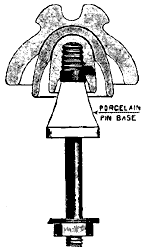
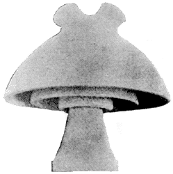
In this connection, it may be stated that in thick and heavy pieces, as were the first insulators, porcelain is very liable to small cracks and flaws, while thin pieces may be burned much more perfectly and thoroughly uniform and vitreous. For these mechanical, as well as electrical reasons, the shell construction was designed, a sectional view of which is shown in figure 5, and an insulator, with this construction, is shown complete in figure 6.
 |
| Figure 7 - No. 307 "Victor" Porcelain Insulator, for 40,000-Volt Line. |
Following closely after the development of high potential insulators, there was a gradual raise of the high potential point and one notable result was the new ruling in regard to the "triple petticoats," a term that is even today, in the minds of a great many users of high potentials, symbolical of the highest and best type of insulators. Now, it will be noted that up to this point the idea is dominant that the more surface embodied in the petticoats between the pin and line the better the insulators produced. But with the higher potentials, it was found that we were contending against insidious surface leakage, and thus by interposing large surfaces in the shape of petticoats in order to insulate, we presented the greatest detriment to efficient insulation. It will readily be seen that were we able to design an insulator with no surface whatsoever, and just distance between wire and pin enough to prevent arcing at potential used, we would have a perfect insulator. Consequently if we designed insulators with the required arcing distance, and with just as small a surface as possible, we then have as perfect an insulator as is possible under present usage.
 |
| Figure 8 - No. 304 "Victor" Combination Insulator for 60,000-Volt Line. |
In general, then we may state that our best designs embody the maximum arcing distance that is possible with a minimum amount of surface, over which static discharge may take place, such insulators to be made of a material having the most favorable hygroscopic properties and the greatest surface resistance and mechanical strength. This material is porcelain, as technically developed.
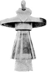 |
| Figure 9 - No. 306 "Victor" Combination Insulator for 60,000-Volt Line. |
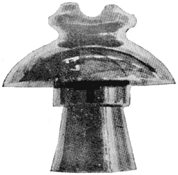
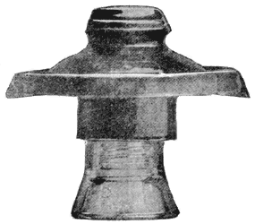
In the "Victor" designs all of the above features are embodied. To attain the proper arcing distance, the top is extended laterally, or in an umbrella shape, and the center is extended down around the support, also preventing arcing to the pin. All other surface is cut out. Figure 10 illustrates one of the earlier of these designs and figures 7, 8 and 9 show three of the latest types.
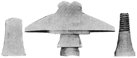 |
| Figure 10 - Early "Victor" Type Insulator, Showing Center. |
These designs, as now built, include insulators for 10,000 to 60,000-volt, actual line potential, and we are now working out insulators for very much higher potentials, since late experiments would indicate that power transmission at potentials far above 60,000 is possible.
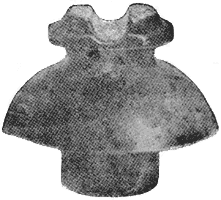 |
| Figure 11 - No. 298 "Victor" Insulator for 20,000-Volt Line. |
I think the above outline gives somewhat of the gradual development, and the cuts convey a very good idea of the designs. Of course there are, or were, very many other designs both in glass and porcelain, some of which have been retained up to the present, while others have been abandoned. The road leading up to the manufacture of modern high tension insulators is literally strewn with petticoats and broken china and glass. I also include a drawing of the No. 298 "Victor" insulator, for 20,000 volts and under.
I wish to say, in closing, that I desire it clearly understood that the eave-trough insulators, of the design illustrated in figure 9 and used by the Bay Counties Power Company and the Standard Electric Company of California, are wholly of my designs and patents. The large saddle and strain insulators used in the great Carquinez span of the Bay Counties Power Company, although made by me, were wholly designed by Mr. R. H. Stirling, superintendent of the Bay Counties Power Company.
I may further add that I have good reason to believe that we will soon be able to insulate and transmit power at potentials running up to 100,000 volts, and even higher, for distances up to, say, four hundred miles.
