[Trade Journal]
Publication: The Telegrapher
New York, NY, United States
vol. III, no. 46, p. 1, col. 1-2
BROOKS' PATENT INSULATOR.
The improved form of insulator invented and patented by Mr. David Brooks, of Philadelphia, is at the present time attracting considerable attention among telegraphers. The readers of this journal have observed the numerous favorable reports which have appeared in its columns respecting the performance of long lines on which this insulator has been for some time in use.
The accompanying illustrations will enable the principle of its construction to be readily understood.
 |
| Fig 1. |
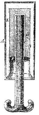
Figure 1 is a vertical section through the center of the insulator. A represents a cylindrical iron casing the lower end of which is open. This is made slightly conical, being of greater diameter at the top that at the bottom. B is a hollow cylindrical block of glass of the same general form as the exterior iron casing, and is placed within it. The space, E, between the glass and the exterior casing is filled with sulphur. C is the wire-holder, which is of cast iron and of the usual form. The shank of the wire holder is secured within the glass cylinder by a quantity of melted sulphur filling the space, C. In order that the shank may not be withdrawn from its place by the weight and tension of the wire, it is made slightly concave on its opposite sides. This is not shown in the figure. It is for this reason also that the glass and iron cylinder are made smallest at the bottom.
In preparing the insulators, the shank of the wireholder is secured within the glass as above described. A sheet of thick paper, D, in the form of a hollow cylinder, is then cemented to the glass entirely surrounding it. The space, E, intervening between the paper and the external casing is then filled with melted sulphur, by means of which, when cooled, the glass cylinder is firmly secured within the external casing.
The insulator being retained in an inverted position, melted paraffine is poured into the space within the paper cylinder until it is filled; the insulator is then turned upside down and the greater part of the paraffine poured out; the remainder adhering to the paper, and to the edge of the casing, and of the sulphur. This layer of paraffine is represented in the figure at F. This is then covered with a varnish composed of beeswax, rosin, and paraffine.
 |
| Fig 2. |
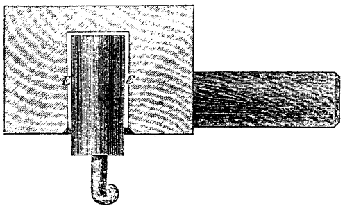
Figure 2 shows the method of attachment to the pole known as the "plug bracket." This is inserted in a two-inch hole bored in the side of the pole, and is fastened with a nail. A sectional view of this bracket is given in the figure in order to show the manner in which the insulator is secured within it. A hole is bored in the bracket of the proper size, and the insulator cemented in with melted sulphur, as shown at E.
 |
| Fig 3. |
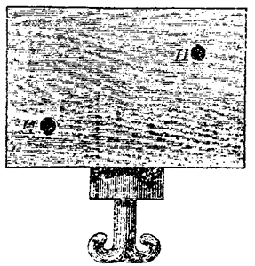
Figure 3 is an insulator of the "block" pattern.
The insulator is also put up in cross arms arranged to carry either two or four wires as may be desired.
It will be observed that in this insulator the glass is hermetically sealed within the iron casing by means of the paraffine, and cannot be affected by moisture. The paraffine itself is a substance repellant of water, and it is impossible for a continuous film of moisture to form upon its surface. It is this fact that renders the Brooks Insulator so much superior to others for working lines in damp and foggy weather.
F. L. P.
