[Trade Journal]
Publication: The Telegraphic Journal and Electrical Review
London, England
vol. 6, no. 118, p. 3, col. 1-2
FULLER'S PATENT INSULATOR.
THE form given to insulators for open telegraph lines has almost invariably been that of an umbrella or bell with curved or parallel sides. Most of these particular forms are no doubt due to careful thought, and have been decided upon after numerous experiments. Many of them, however, are such as would lead one to doubt whether any consideration had been given to the obvious rules which must be followed if both mechanical strength and high insulation in all weathers, are to be obtained.
 |
| Fig. 1. |
 |
| Fig. 2. |
The insulator, recently introduced by Mr. Fuller, seems to possess these two necessary qualification in a high degree. Its form is that of an inverted truncated cone, by which not only great mechanical strength is provided at that portion of the insulator which has hitherto been found to be weak, and which frequently bursts from the expansion of the iron bolt to which the porcelain is fixed, but with the converging sides of the cone, the insulation is vastly improved by the surface over which the leakage can take place being comparatively small.
The particular shape of the improved insulator renders it less liable to the retention of any dust or moisture on its surface than is the case with insulators of the usual forms, while the danger from either external or internal fracture is reduced to a minimum.
The resistance offered to the escape of the electric current over the surface of the porcelain, is still further increased by corrugating, serrating, or under-cutting the outside surface of the cone. By this means the downward flow of any moisture which may collect on the surface of the porcelain is broken at several points, and consequently a continuous conducting film can only be formed with great difficulty, it at all.
Another feature in the improved insulator is the method by which the two parts of the insulator, an inner and an outer cup, are fixed together. Instead of employing cement for this purpose, which would rigidly connect the two parts, Mr. Fuller uses a tightly fitting india rubber ring. By the employment of the latter it is possible to separate the two parts for examination, cleaning or renewal, without unbinding the line wire. This is a very great point, and is, we believe, a feature possessed by no other form of insulator. The elastic connection between the two parts must render their liability to break from unequal expansion or from any sudden jar to the wire, very small; also the high insulating property of the rubber must be very beneficial.
In the iron supports or bolts in common use, it is found that the nut and screw required for fastening the insulator to the bracket becomes fixed together so firmly by rust, that great difficulty is experienced in removing the nut when it is necessary to shift the insulator. Mr. Fuller gets over this difficulty by the simple expedient of using a bolt having a slot at the lower end through which a wedge is driven.
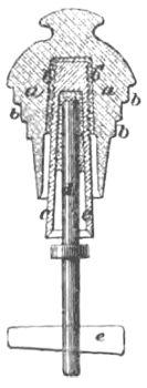
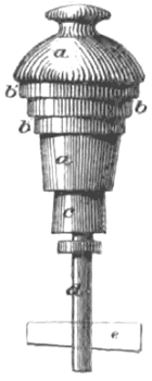
Fig. 1 is a vertical section, and fig. 2 a side elevation of the insulator. a is the inverted truncated cone portion, and b b are the corrugations, serrations, or under-cuttings thereon.
The separate inner cup is also shown in fig. 1, where c represents the inner cup and b' the vulcanized india rubber ring, d is the metal support insulated, as shown, from the inner cup c.
If preferred, the inner cup c may, of course, be cemented to the inverted cone a, though the advantage of the elastic connection would be lost thereby.
e e, figs, 1 and 2, show the wedge or cutter passing through a slot in the metal support d.
