[Trade Journal]
Publication: The Electrician & Electrical Engineer
New York, NY, United States
vol. 4, no. 3, p. 88, col. 1-2
THE CONSTRUCTION OF LINES FOR ELECTRIC CIRCUITS.
BY THOMAS D. LOCKWOOD.
THE clothes-pin attachment, like most great conceptions, is exposed to the fate of being Hon. Amos Kendall, the early agent of Morse, was, before 1850, delivered of the following remarkable system of insulation which we give in his own words: "I think the following the cheapest mode of insulation vet devised, and as effectual as any: With a wide set saw, or Otherwise, make a gap in the post downwards, at all angle of 45°, wide enough to receive the wire with its covering. Just cover the wire with the best india-rubber cloth, or a composition of which india-rubber is the chief ingredient, so far that the covering shall extend about 2 inches from the post on each side. Over that, wrap sheet-lead or tinfoil, not, however, extending more than an inch on each side of the post. Sink the wire so covered into the gap on the post, then pass large twine turned around the lead covering on each side of the post, and tie it tight round the side of the post opposite to the gap. It will have the double effect of confining the lead and turning off the water." Happily for the memory of Mr. Kendall he never tried this alleged insulator.
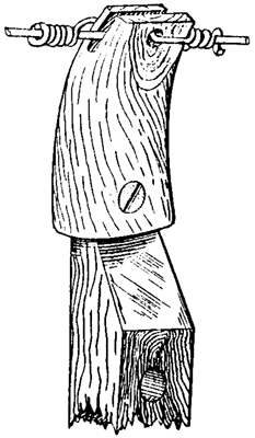
Another brilliant idea is embodied in the "picture" below. It was first introduced into civilized society by an article in the New York Electrical Review, based upon a letter from Aguascalientes, Mexico, which states that the Zacatecas state telegraph lines use these apologies almost exclusively. The attachment itself, as clearly shown in the figure, is a piece of horn, with tip and butt sawn off, and a notch cut in the top. It is, of course, hollow, and surrounds the top of the bracket to which it is screwed. The line wire is passed through the notch and held there, by being fastened with a piece of No. 14 wire. The letter describing this remarkable appliance naïvely states that "these horn insulators, although poor insulators for telegraph, are splendid anti-induction insulators for telephonic use." This statement lets the cat out of the bag. The horn insulators are poor for telegraphic purposes, because they are not insulators at all. Horn is not very much of an insulator at best, having about the same specific resistance as the hard skin of the hand of a laborer, and whatever insulation it possesses is lost by the method of fastening the wire. It is because of this non-insulating character that it will answer in a dry country for telephonic purposes, affording just sufficient leakage to keep the line clear of static induction. It is, however, probable that if the horn was dispensed with altogether, and the wire fastened directly to the bracket or pin, it would work just as well in dry weather. In wet weather, it is not likely that either wood or horn would prove eminently satisfactory, even for telephonic service.
 |
| Figure 6. |
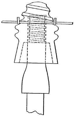
It is a pleasure to look away from these oddities, to an invention in insulators which possesses real merit, and which, when better known, will be extensively employed. I refer to the form of insulator shown in figure 7.
 |
| Figure 7. |
A glance will show the nature of the improvement. In addition to the regular internal screw thread with which the insulator is as usual attached to the pin, there is an external screw on the apex of the insulator, but oppositely wound. That is, if the internal screw is right-handed, the external one is left-handed and vice verse.
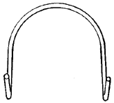
The line-wire instead of being bound to the insulator with a tie-wire, is fastened with a special clip which is shown detached, in figure 8.
 |
| Figure 8. |
The object in providing the right and left-handed screws, is so that the wire can be fastened to the insulator, and the insulator screwed down on the pin by one and the same operation.
In attaching the wire, the insulator is placed on the pin and given a couple of turns down. The clip is hooked on the line-wire with the ends of the hooks turned upwards. The loop thus formed is then slipped over the top of the insulator, and (care being taken to see that the clip goes down the thread of the screw first with the line-wire following) the insulator grasped by the hand, is screwed clown on the pin as far as it will go, the outside screw at the same time insinuating itself into the loop of the line-wire and clip. These instructions for attachment, are by no means intended to serve as ironclad rules to be observed, but an intelligent lineman observing the intention of the improvement, will readily adapt himself to it, and act according to the different conditions of each case. Even if insulators of this character are employed, circumstances may of course arise in which it will be found desirable to use the old mode of attachment. The insulator as now made, is provided with the ordinary circular groove, upon which the line-wire rests, for attachment with the old time tie-wire.
It is, perhaps, unnecessary to recapitulate the advantages which are secured by the use of this form. It is well-known that a concomitant trouble of the old form of attachment was that scales of the zinc coating were sure to be rubbed off, thus leaving spots of unprotected iron wire at which oxidation would promptly commence. The leakage at each insulator may also be reasonably expected to suffer diminution, as the points of contact are lessened; while the line-wire suffers much less mechanical strain. It is also claimed that much time is saved in construction by its use, and it is evident that a single clip may be used many times, and that if it becomes necessary to detach the line-wire at any time, a few backward turns of the screw is the only operation necessary. Practical linemen whose opinion I have asked on this subject, concur in praising it highly and advocate its use, and it would therefore seem that one of the greatest obstructions which threaten innovations, e., the opposition of workmen, will not retard the introduction of this insulator.
The application of the external or wire attaching screw, is the invention of an Englishman, J. Slater Lewis, and has been patented, in the United States. The happy conception of forming the outside screw of opposite direction to the internal or pin screw, so as to provide for the simultaneous attachment of both line-wire and insulator is, however, to be credited to Frank L: Pope, and is fully described in a patent issued to that gentleman, December 25th, 1883. Both patents have, for the entire country, passed into the hands of the National Insulator Company, of which Messrs. Loren N. Downs and II. B. Lytle, of Boston, are respectively President and General Manager, and J.W. Duxbury, of Providence, R. I., Treasurer. These gentlemen recognizing the practical merit of the combination, and having, moreover, control of other improvements in insulators, have established themselves in the Equitable Building in Boston, and will doubtless take pleasure in furnishing any additional information that may be required upon the subject.
SUPPORTS FOR AERIAL LINES.
These are of twofold character—poles set in the ground, and house-top fixtures fastened upon the roofs and walls of buildings. The habitual haste and hurry of this nation is fully exemplified in the way telegraph poles are treated, from the moment they are cut until they are finally discarded. In the early days of the American telegraph, lines were hurriedly built for fierce competition—poles were set immediately after they were cut, often while the sap was still running, and sometimes without even being barked. The result was a short life and by no means a merry one. This reminiscence is forced upon my mind by the way in which the sad history is even now repeating itself. The lines for the telephone were built much more rapidly than those of the early telegraph; sometimes by men who had been to school in telegraphic construction; more frequently by men who had served no such apprenticeship, and who had, as it were, to learn a completely new business. How should they know that poles should be cut at least six months before they were to be used? And if they did know, had they time to wait? Nor is it an easy matter to persuade these gentlemen that it is wise to paint all poles, or to char the bottoms. The ten cents present is usually a more potent consideration than the dollar to be saved hereafter.
But two materials for poles need be discussed—iron and wood, and the latter is used almost universally in American construction.
The kinds of timber used for this purpose are principally the red and white cedar, chestnut, redwood, cypress and juniper. Spruce and pine are used to some extent, but they are not to be recommended. Where it can be readily procured at a reasonable cost, the red cedar is for all practical purposes to be preferred. It is not a handsome wood to look at, but is very durable, and lasts longer than any other which has come under my observation. Chestnut is also very good, being tough, elastic and tenacious of life. The white cedar also makes a fair pole, but is more brittle and addicted somewhat to snapping off short, when it receives an unusual strain. Cypress and juniper are much used in the south, but the latter seems to be preferable; inasmuch as cypress in a moist, warm climate is easily attacked by dry rot, which materially shortens its life. Juniper is a rather coarse grained wood, but is said to be very strong and durable.
All poles should be cut in late autumn or winter, when the sap ceases to rise. Careful estimates show that this precaution adds some years to the life of a pole.
A report furnished by the Western Union Telegraph Co. to the Superintendent of the United States census and published in 1882, show the average length of poles to be 27 feet, diameter across the top, 6 inches ; average cost of each pole, not counting freight, $1.02; and the further statement was made, that the average life of a pole according to the wood used, and the location, was from 12 to 15 years, and in no case exceeded 25 years.
After cutting, they should be trimmed, stripped of their bark, shaved smooth, and then stacked for 5 or 0 months in stick a way that the air may freely circulate between them, the lowest tier of the stack being raised a few inches from the ground.
POLE PRESERVING PROCESSES.
Wooden poles have been found to suffer severely from both dry and wet rot, but especially from the latter. They are particularly subject to decay at the ground line. To counteract these destructive agencies, the English constructors have from time to time adopted various preservative processes, applying them to poles before setting them up. These have been of two kinds:
First,—The impregnation of the poles with a strong solution of some metal salt, which salt combining chemically with the vegetable juices, produces compounds unfavorable to decay.
Second,—To impregnate the poles thoroughly with creosote.
It is not necessary to describe the former processes, since it is most unlikely that any of them will be adopted by American constructors.
Creosoting is accomplished by placing the poles in an iron receiver, exhausting the air front them and then forcing boiling creosote into them under pressure. This process has always given such eminent satisfaction that in the future when our timber is less plentiful than at present it will possibly be adopted. It has not, in the United States, as yet been thought desirable to employ any of these processes, as our supply of timber is yet large, and it is also thought that American timber is of a more durable character than that of Europe.
The statement is made that unprepared American timber will last as long as the prepared European poles; but an exception must be made in favor of those prepared with creosote. One protective process invariably used in England, we might, t think, profitably import, particularly as it is neither complicated nor expensive; that is the practice of roasting the butt end of poles in a slow fire until they are well blackened, for about 5 or 6 feet up, before setting them (care being taken not to burn them), and then tarring the blackened part and bottom with a mixture of coal and wood tar, and slacked lime. This compound operation prevents moisture from entering the buried part of the pole.
(to be continued.)
